
9. Deformation of the Bulk Solid in the Hopper
The stresses developing in a hopper depend on the deformation of the bulk solid. This is illustrated in the following by a simplified model where the bulk solid in the hopper is subdivided in horizontal layers.It is assumed that an initially empty hopper is filled with bulk solid layer by layer. Since the weight force of every layer filled into the hopper acts on the layers below, the bulk solid in the hopper is compressed vertically (Fig. 16.a). Thus, during filling the vertical stress in the bulk solid is increasing due to gravity. Depending on the compressibility of the bulk solid, the layers are compressed more or less in vertical direction (Fig. 16.b). Thus, the layers are moved a bit downwards. Due to the converging shape of the hopper, this results in a small horizontal compression (smaller than the vertical compression) which shall be neglected for now for reasons of simplification.
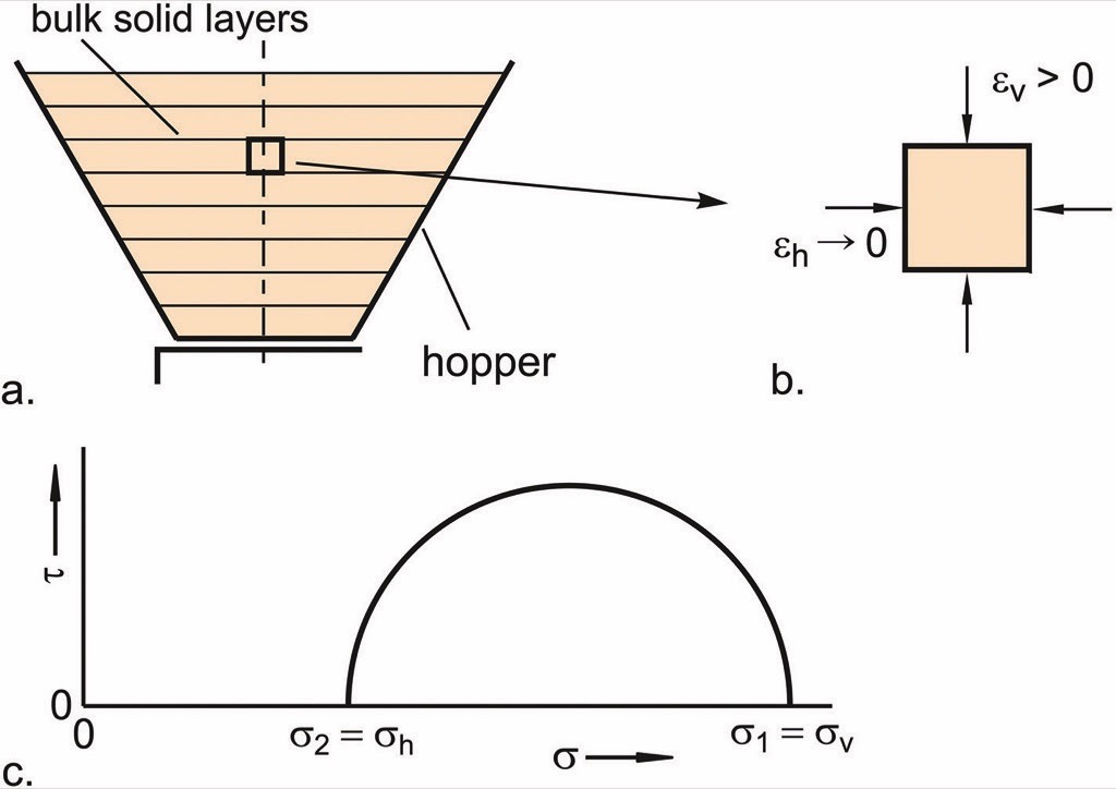
In the vertical section of a silo the conditions are similar to a hopper in the filling state since in both situations the bulk solid is compressed in the vertical by the force of gravity. In part 1 of the present paper (Fig. 4 in [10]) it was outlined that this kind of compression results in the vertical stresses being larger than the horizontal stresses. The same happens in the hopper in the state of filling: The major principal stress of the Mohr stress circle representing the stresses in the silo axis (Fig. 16.c) is equal to the vertical stress, and the minor principal stress is equal to the horizontal stress. This stress state is known as the stress state of filling, or filling conditions.Next, the stresses developing while the hopper is discharged are regarded. It is assumed that the hopper is sufficiently steep to obtain mass flow. Mass flow is defined as the flow profile where the entire content of a silo moves downwards during discharge, i.e., no stagnant zones are formed as in a funnel flow silo. To attain mass flow, the hopper walls must be sufficiently steep. Furthermore, the bulk solid must be withdrawn from the entire outlet opening [1, 2].Flow in a hopper is initiated by the withdrawal of the bulk solid through the outlet opening. Thus, the vertical stress acting on the bulk solid in the hopper is relieved. Simultaneously, while flowing downwards in the mass flow hopper, the bulk solid is compressed horizontally due to the converging shape of the hopper (horizontal strain εh > 0, Fig. 17.a), resulting in higher horizontal stress compared to the vertical stress. Thus, the bulk solid is not compressed in the vertical direction as outlined above for the filling process, but compressed horizontally while expanding vertically as shown in Fig. 17.b (this is a simplified explanation which in the strict sense is valid only for the silo axis; in reality towards the hopper walls the direction of compression is increasingly inclined to the horizontal). As a result of the latter, the horizontal stress in the hopper axis is greater than the vertical stress. This stress state resulting from the discharge process is called the stress state of emptying, or just emptying conditions.
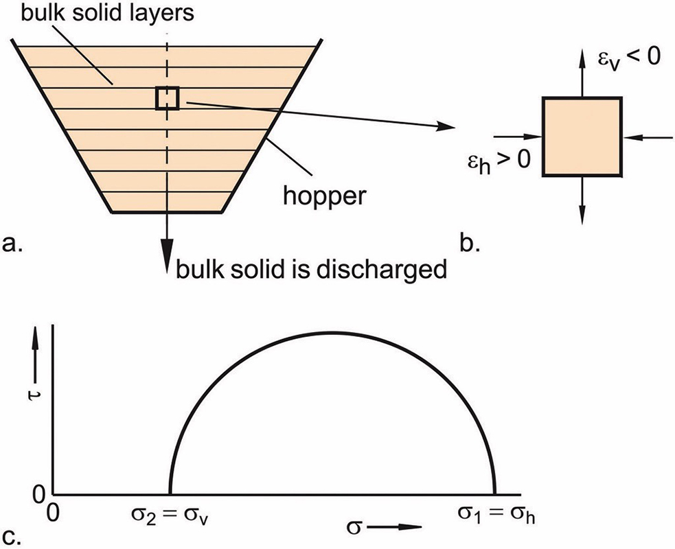
A Mohr stress circle representing the conditions in the hopper axis in the stress state of emptying is shown in Fig. 17.c. In contrast to the stress state of filling, here the major principal stress, σ1, is equal to the horizontal stress, σh, and the minor principal stress, σ2, is equal to the vertical stress, σv. However, the ratio of the minor to the major principal stress in emptying conditions is smaller than the lateral stress ratio, K, valid for the conditions in the vertical section. The reason for this difference is the different deformation: In the vertical section, the bulk solid is compressed only uniaxial (vertical direction) because the vertical lateral walls do not allow horizontal deformation. To the contrary, while flowing downwards in the hopper, the bulk solid is not only compressed horizontally, but can expand in the vertical direction. The expansion reduces the stress acting perpendicular to the direction of compression compared to uniaxial compression [1, 2].Fig. 18 illustrates the different stress conditions. Three Mohr stress circles with identical major principal stress, σ1, are drawn in a σ-τ-diagram (identical values of σ1 have been chosen just for illustration purposes; of course, at different positions in a silo or hopper the major principal stresses are different). The mean stress circle (solid) represents the stresses along the axis of the silo’s vertical section where the bulk solid is subjected to uniaxial compression in the vertical direction. The stress state of emptying in the hopper is described by the dashed stress circle. As outlined in the previous paragraph, the minor principal stress is smaller compared to the stress circle for the vertical section (uni-axial compression) because the vertical stress is reduced due to the vertical expansion of the bulk solid.
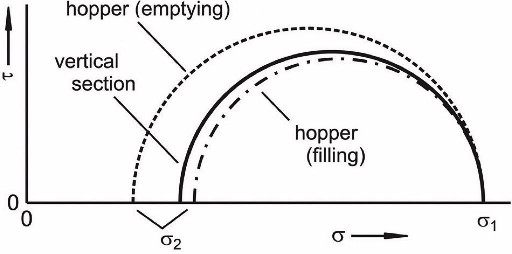
The stress state of filling in the hopper axis is represented by the dot-dashed stress circle. If one assumes that the bulk solid in the hopper is compressed vertically during the filling process, one can expect a certain horizontal compression due to the convergence of the hopper, i.e. the cross-section of the hopper is decreasing downwards. Thus, the minor principal stress, σ2, is somewhat larger than that evolving at uniaxial compression where no compression takes place in σ2-direction [1, 2, 11].If the emptying process is paused, the stresses remain in the stress state of emptying as depicted in Fig. 17.c. There is no switch back to the stress state of filling.
10. Stresses in Silos with Hoppers
The different stress conditions at filling and emptying of a hopper result in different stress distributions. Fig. 19.a presents the mean vertical stress, σv, and the wall normal stress, σw, acting normal to the walls directly after a previously empty silo has been filled (stress state of filling). The stresses in the vertical section show the typical behavior as explained in part 1 of the present paper [10]. The vertical stress is greater than the horizontally oriented wall normal stress which is identical to the horizontal stress.
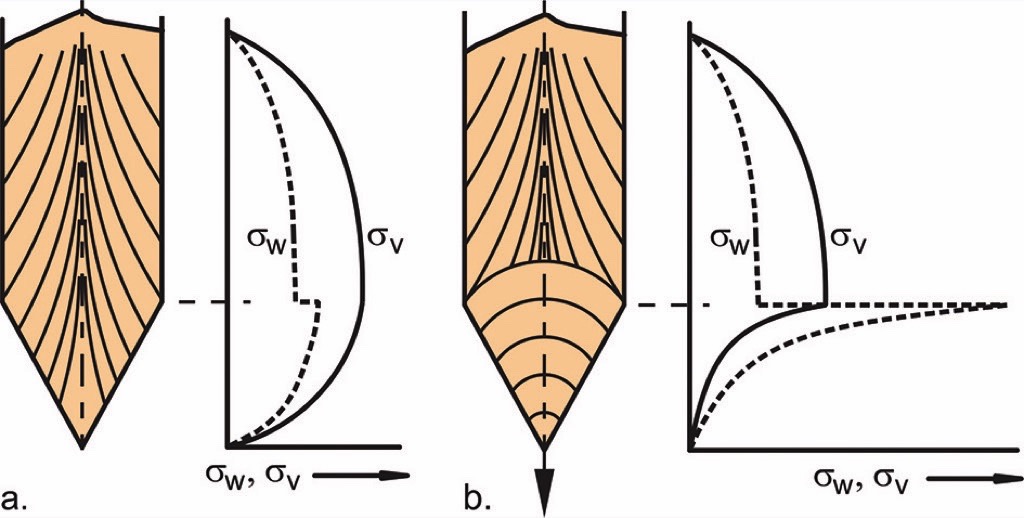
Major principal stress lines drawn on the bulk solid in Fig. 19 are indicating the orientation of the major principal stress, σ1. In the silo axis the major principal stress is oriented vertically. Towards the wall the direction of the major principal stress becomes increasingly inclined to the vertical since shear stresses (wall friction) are acting on the walls. However, simplifying these conditions one can say that the major principal stress in the vertical section is roughly oriented vertically.The hopper stresses in the filling condition are similar to the stresses in the vertical section. In both situations the vertical stress, σv, is greater than the wall normal stress, σw. However, in case of the hopper, as a result of the wall slope the wall normal stress is oriented in a different direction than the horizontal stress. Further, the major principal stress is inclined more to the vertical in the vicinity of the hopper walls than close to the walls of the vertical section (see major principal stress lines in Fig. 19.a). For the following explanations these differences are of less importance and, thus, neglected.A substantial difference between the stresses in the vertical section and the hopper is the convex shape of the vertical stress in the hopper which is approaching zero towards the hopper apex (“infinite small outlet opening”). The latter can be explained by the fact that towards the outlet the ratio of perimeter to cross-sectional area increases. Therefore, towards the outlet opening, each layer of bulk solid is increasingly supported by the hopper wall which results in a decrease of the vertical stress. This behavior can be roughly compared with the stresses in the vertical section (see part 1 [10] of the present paper, or [1, 2]): In the vertical section the final vertical stress, σv∞, is proportional to the diameter.If bulk solid is discharged from the hopper, or a certain amount of bulk solid has been discharged previously, the stress state of emptying is present (Fig. 19.b). In Section 9 it has been outlined that the major principal stress in the hopper at emptying conditions is roughly oriented horizontally (with increasing divergence from the horizontal towards the hopper walls due to the shear stress at the inclined walls). Accordingly, the wall normal stress in the hopper is greater than the vertical stress (Fig. 19.b). Thus, the directions of the major principal stresses are inverse to the filling conditions.In emptying conditions where horizontal stresses are larger than vertical stresses, the bulk solid in the hopper is supported by the hopper walls to a greater extent than in filling conditions. This results in a strong increase of the wall normal stress at the transition from the vertical section to the hopper, and a more pronounced decrease of stresses towards the outlet opening. Due to the latter, the emptying stresses in the lower part of the hopper are smaller than the stresses at filling condition which is especially true for the vertical stress. Further, the stresses in the lower part of the hopper are proportional to the local hopper diameter.The sudden increase of the wall normal stress at the transition from the vertical section to the hopper is called the switch stress peak. The word “switch” points to the change of the orientation of the major principal stress at the transition (see major principal stress lines in Fig. 19.b). The major principal stresses in the silo axis near the transition are plotted in Fig. 20.a as arrows with the length of an arrow being a qualitative measure of the magnitude. Since the flowing bulk solid within the hopper has some influence on an arched region in the lower part of the vertical section, a dashed arc is drawn as the boundary between the stress conditions of the vertical section (above arc) and the stress conditions of the hopper (beneath arc).
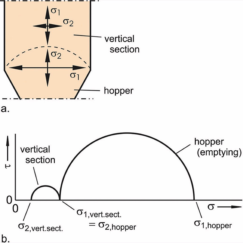
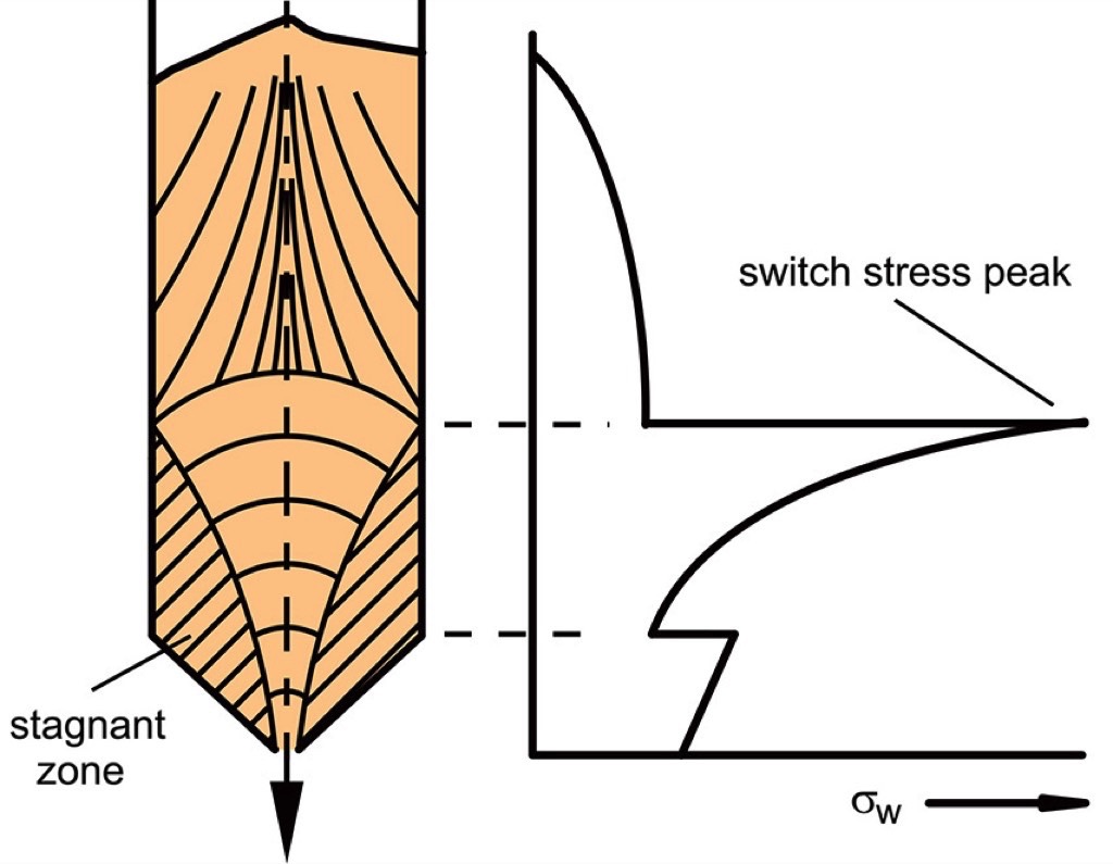
In the lower part of the vertical section (above the arc), the major principal stress, σ1, is oriented vertically, but beneath the arc it is oriented horizontally while the minor principal stress acts vertically. Since the vertical stress above the arc has to be in equilibrium with the vertical stress from below, the major principal stress above the arc (vertical section) is equal to the minor principal stress below the arc (hopper), as it is illustrated in Fig. 20.a by the stress arrows. Thus, the horizontal stress below the arc (σ1 close to the top of the hopper) is clearly larger than the horizontal stress above the arc (σ2 close to the bottom of the vertical section). The latter illustrates the sudden increase of horizontal stress and wall normal stress, respectively, at the transition from the vertical section to the hopper.In Fig. 20.b the stresses above and below the arc of Fig. 20.a are represented by Mohr stress circles. Because of the equality of the vertical stress above and below the arc, the stress circles have a common point at this stress representing the minor principal stress below the arc (σ2,hopper) and the major principal stress above (σ1,vert.sect). The other principal stresses (σ2,vert.sect and σ1,hopper) of both stress circles are acting in the horizontal direction. The significant difference between these stresses resulting in the stress peak is obvious.Even in funnel flow silos a switch stress peak can occur (Fig. 21). If the boundary between a stagnant zone and the flow zone meets the silo wall within the vertical section (in sufficient distance to the filling level), a stress peak occurs since the stagnant zone acts like a hopper. On top of this “bulk solid hopper”, the orientation of the major principal stresses is changed in the same way as in a silo hopper which results in a switch stress peak at the upper edge of the stagnant zone.
Funnel flow causes a couple of inconveniencies with respect to flow and segregation [1, 2], and is accompanied by a switch stress peak resulting in an unfavorable situation for structural silo design. The problem is that the stress peak in a funnel flow silo acts in the sensitive vertical section where its position cannot be accurately predicted because it is generally not possible to predict the shape of stagnant zones. Even in a silo which is repeatedly filled with the same bulk solid the shape of the stagnant zones can vary. Thus, the complete vertical section has to be designed accordingly [6].The stress peaks drawn in Figs. 19 and 21 are rather sharp. It must be assumed that in reality, depending on the bulk solid (compressibility is likely to play an important role), also less sharp stress peaks with a smaller maximum, but acting over a larger area, may occur [1, 2].
11. Filling Stresses and Emptying Stresses
A comparison of the stresses in filling and emptying conditions (Fig. 19) shows that the stresses acting in the lower part of the hopper are clearly larger in the filling state. This is especially true for the vertical stress. Most hoppers end with an outlet opening in this region, and often a feeder is installed beneath the outlet opening. Therefore, in most cases the vertical stresses acting near the outlet (and on the feeder, if present) are larger in filling conditions than in emptying conditions. Some consequences of this behavior are:
- If a previously empty silo is filled without discharge during filling, or shortly after filling, the stress state of filling is preserved for a longer period. Bulk solids with a tendency to time consolidation (increase of strength with time [1, 2]) may become so strong that stable arches or ratholes are formed, and discharge is not possible without further means.
- At filling conditions, the vertical stress acting on a feeder (e.g., chain feeder, screw feeder) attached to the outlet opening can be very large. To start the feeder, its drive must be able to move the bulk solid under the high vertical stress at the outlet. Due to the large vertical stress, large friction forces have to be overcome (e.g., the internal friction of the bulk solid). For this situation a feeder must be sufficiently stable, and provided with an appropriate drive.
The problems mentioned in the two paragraphs above can be solved by avoiding the stress state of filling. This can be done in the following ways:
- While filling a previously empty silo, bulk solid is continuously discharged with small discharge rate, or discharged intermittently. Due to the flow in the hopper, the stress state of emptying prevails.
- If complete emptying is avoided, a material cushion (best the entire hopper contents, or at least a major part of the hopper filling) remains in the silo so the stress state of emptying is preserved.
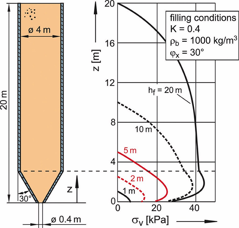
If the stress state of filling cannot be avoided, it might help to place an insert above the outlet opening. If appropriately designed, the insert reduces the stresses in the lower part of the hopper. Care has to be taken to avoid that the insert causes flow problems [1, 2].In principle, the stress at the outlet opening at filling conditions can be limited by a small filling level, but with this method an effective reduction of the stress is attained only at small filling levels. The reason is the supporting action of the silo walls. In Fig. 22 vertical stresses acting in an exemplary silo are plotted for different filling levels, hf, ranging from 1 m to 20 m. A general statement on this effect is not possible because in the stress state of filling the stresses near the outlet opening are not only dependent on the bulk solid properties, but also on the shape of the hopper and the outlet dimensions.
12. Calculation of Stresses acting in the Hopper
Slice element methods similar to the Janssen approach [7] explained in part 1 [10] of the present paper are relatively simple means to calculate hopper stresses for the stress states of filling and emptying. However, due to the conditions in a hopper, the equations are more complicated and more assumptions are needed. Since a detailed explanation would exceed the scope of the present paper, the reader may refer to the literature, e.g., [1, 2, 11, 13, 14]. A PC program for the assessment of stresses acting in silos developed by the author uses the above mentioned approaches [12]. However, filling stresses depend on a couple of quantities and conditions so they cannot be calculated very accurately.For a very rough assessment of the order of magnitude of the vertical stress, σva, at the outlet opening of a mass flow hopper in the stress state of emptying the following equations may be used:Conical hopper (outlet diameter, d):

Wedge-shaped hopper (width of outlet slot, b; length of outlet slot, L > 3·b):

As stated above, the stresses at the outlet opening in the stress state of filling cannot be calculated very exactly. Experimental results (e.g., [11]) indicate that the vertical stress acting at the outlet at filling conditions (after filling an previously empty silo) can be five to ten times the vertical stress at emptying conditions.
13. Local Variation of the Cross-Section
In part 1 [10] of the present paper the stresses developing in the silo’s vertical section were discussed, and it was assumed that the vertical walls are strictly parallel. If this is the case, the bulk solid in the vertical section is compressed only vertically by the weight force, while the horizontal dimensions of each bulk layer in the horizontal remain constant. For the so-called uniaxial compression, the lateral stress ratio, K, defines the fixed relationship between the horizontal stress, σh, acting on the wall, and the mean vertical stress, σv [1, 2, 10].In reality a vertical section of a silo with an ideally, perfect shape, e.g. a perfect cylinder, is unlikely to occur. A real vertical section will have more or less pronounced imperfections resulting in local convergences or divergences. Imperfections have an effect on the stresses especially when the bulk solid is flowing, i.e., at emptying a silo. That is because a layer of bulk solid which after filling has a certain horizontal width, or diameter, is deformed while passing an imperfection (Fig. 23). In case of a local convergence the bulk solid is compressed horizontally, in case of a divergence it can expand horizontally. While filling a silo similar tendencies can be expected, but their effect on the stresses is less pronounced. The latter has been shown by investigations on silos with convergences formed by inserts [15]. Therefore, here the emptying process is regarded.
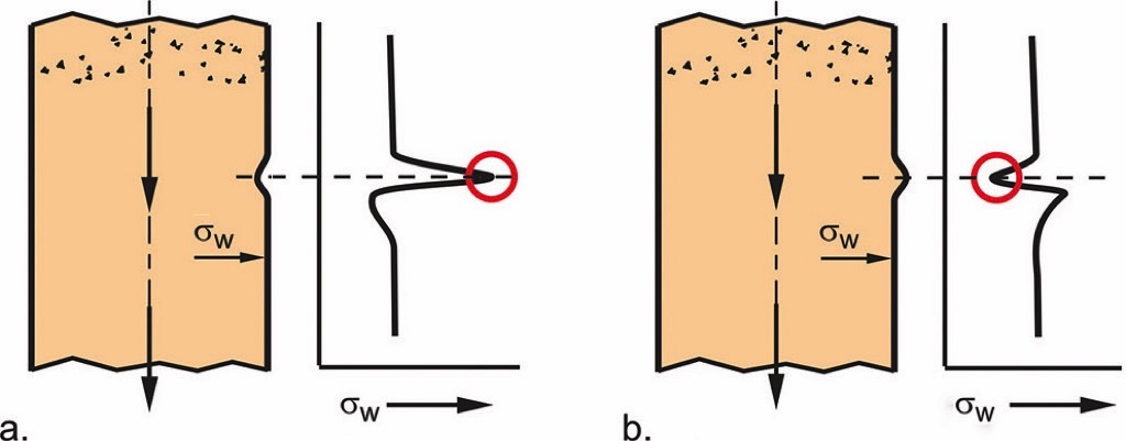
The horizontal compression due to the local convergence results in a local increase of the horizontal stress, or wall normal stress, σw, respectively (Fig. 23.a, red circle). On the contrary, the local divergence reduces the wall normal stress (Fig. 23.b, red circle). Although this can be easily described qualitatively, it is difficult to obtain accurate quantitative statements on the resulting stresses.Even below an imperfection its influence is noticeable since the deformed bulk solid is traveling downwards. Directly beneath a local convergence a stress drop, beneath a local divergence a stress increase is to be expected (Fig. 23). The reason is that a bulk solid layer (especially in case of a cohesive material) is primarily deformed plastically (e.g., by local compaction) while passing a convergence, or divergence. Thus, the effect on the stresses is likely to depend on the bulk solid’s properties such as elasticity and compressibility.It can be assumed that even the ocurring stresses far below an imperfection are affected by the same when the bulk solid, after having passed the imperfection, is flowing further downwards. However, here only the first local stress peak resulting from the convergence is regarded.The magnitude of a stress change depends, among other quantities, on the stiffness, or compressibility, respectively, of the bulk solid, and the magnitude of the local convergence. If, e.g., a fine powder is compressed only to a small extent by a small local convergence, the increase of stress will be small and is likely to be concentrated to the vicinity of the convergence. By the small increase of stress, the powder is compressed sufficiently to pass the convergence.If the convergence is larger and/or the bulk solid is barely compressible (e.g., coarse gravel), only local compression of the bulk solid is not sufficient to pass the convergence. Thus, the convergence will affect the stresses in a larger region which may spread throughout the silo’s cross-section. In Fig. 24.a the wall normal stress distribution of a silo provided with an artificial imperfection (convergence) is shown [16]. The significant peak of the wall normal stress, σw, in the region of the imperfection is similar to the stress peak at the transition from the vertical section to the hopper.
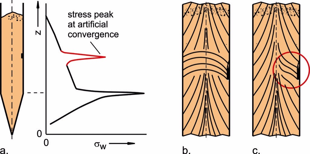
As outlined above, the horizontal stress increases due to the deformation in the region of the convergence. As a consequence, the orientation of the major principal stress is changed (Fig. 24.b). The major principal stress in the vertical section above the imperfection is acting vertically (and is increasingly inclined towards the walls [10]), but near the convergence it changes its orientation towards the horizontal due to the increase of horizontal stress. Thus, the stress conditions are similar to those found at the transition from the vertical section to the hopper of a mass flow silo (see Section 10).While in Fig. 24.b the local convergence affects the entire cross-section of the silo, as it is likely to expect in case of a large convergence, or a stiff, barely compressible bulk solid, in Fig. 24.c the conditions for a more compressible bulk solid at a not too large convergence are illustrated. The major principal stress changes its orientation only in a smaller region in the vicinity of the convergence (red circle in Fig. 24.c).The qualitative result of the considerations above is: The more the silo cross-section is reduced by an imperfection, and the less compressible the bulk solid, the more probable is a re-arrangement of the major principal stress over the entire cross-section as it happens at the transition from a vertical section to a mass flow hopper (Fig. 24.b).An accurate calculation of the stresses resulting from local imperfections is not yet possible. Small convergences due to inaccuracies of the vertical section’s walls are likely to result in a limited increase of the local stress, and, thus, will not lead to severe problems in most cases. If objects reducing the cross-section (e.g., level sensors, ladders, air injection nozzles) are installed in the vertical section of a silo, it has to be considered that these objects not only increase the (local) stresses, but are subjected to (often unexpected) high loads. It is not recommended to calculate loads acting on such objects with Janssen’s equation [7] because this way the local stress increase is not taken into account [15].
14. Inserts
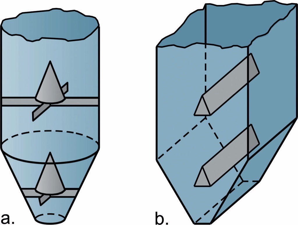
In Fig. 25 typical inserts are shown. Cylindrical silos are often provided with inverted cones (Fig. 25.a) while in silos with rectangular cross-section mostly wedges are found (Fig. 25.b). Also other shapes are imaginable (e.g., horizontal tubular inserts), but not necessarily meaningful. Only inserts with sufficiently steep roofs, or walls, can ensure that no stagnant zones can be formed on the inserts, finally resulting in flow problems (generally mass flow should be sought for). Inserts are used for various tasks. A typical one is the injection of gas [1, 2].
Inserts reduce the local cross-section of a silo. Thus, they create local convergences and act similar as imperfections discussed in Section 13. Since inserts are larger than a typical imperfection, and the shapes of inserts are defined, more knowledge based on research projects exists on their behavior in silos. Some research results are presented in the following. Please note that in the present paper the word “insert” means a typical insert according to Fig. 25.If an insert is sufficiently large, it results in similar stress conditions as found in mass flow hoppers (see Section 11). Loads and stresses on inserts and adjacent silo walls depend, among other parameters such as geometry and dimensions, on the position of the insert (vertical section, hopper), and on the stress state (filling or emptying conditions). As a rule, greatest loads and stresses are found for inserts in the vertical section at emptying conditions, i.e., in the flowing bulk solid. Loads on inserts at filling conditions, and on inserts in hoppers beneath the switch stress peak are smaller in most cases [1, 2].The reason for the high loads on inserts in the vertical section at emptying conditions is the change of the orientation of the major principal stress, similar as outlined in Section 13 regarding imperfections, and similar to the transition from the vertical section to the hopper (Section 10). In Fig. 26.a major principal stress lines are drawn. Above the insert the major principal stress is acting roughly vertically as usual for a vertical section [1, 2, 10]. Between insert and silo wall a converging zone like a hopper is formed which results, as known from a mass flow hopper, in the major principal stress being roughly oriented horizontally. The reorientation of the major principal stress results in a switch stress peak of the wall normal stress, σw (see Fig. 26.a and Section 10). Similar stresses, even a stress peak, are acting on the insert. They are responsible for relatively high loads on the insert which can be strongly non-symmetric in case of a non-symmetric insert position [15], or non-symmetric flow. Beneath the insert the major principal stress reorients to the predominantly vertical direction.
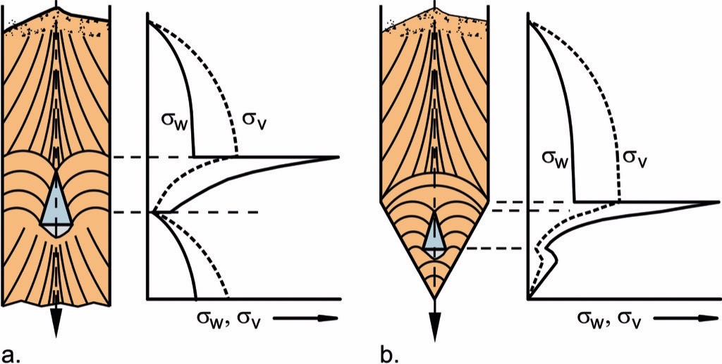
Inserts in hoppers, positioned below the region of the switch stress peak, are in most cases subjected to smaller stresses than inserts in vertical sections. At emptying conditions, the major principal stress in the hopper is already oriented horizontally. A further convergence due to the insert does not change the orientation of the major principal stress significantly and, thus, no switch stress peak develops at the upper edge of the insert (Fig. 26.b) [1, 2].
15. Eccentric Flow
Eccentric flow is present when the bulk solid in a silo does not flow uniformly across the cross-section of a silo, but predominantly in an asymmetric flow zone on one side of the silo, often close to the silo wall (Fig. 27.a). The bulk solid in the flow zone is supported by friction (shear stress, τ) to the silo wall (if the flow zone touches the silo wall) and the friction to the stagnant material. Thus, the flow zone behaves similar to the bulk solid in a slender silo with the diameter of the flow zone. As outlined in part 1 of the present paper [10], the final (maximum) stress in a cylindrical silo is proportional to the cylinder diameter. Therefore, the stresses in the flow zone (small diameter) are smaller than the stresses in the stagnant material around the flow zone (larger diameter).
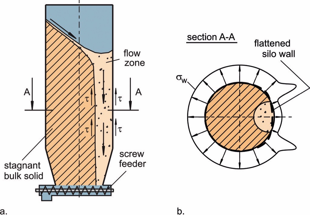
b. Section A-A schematically depicts the distribution of wall normal stress, σw, along the circumference, and the resulting deformation of the silo wall.
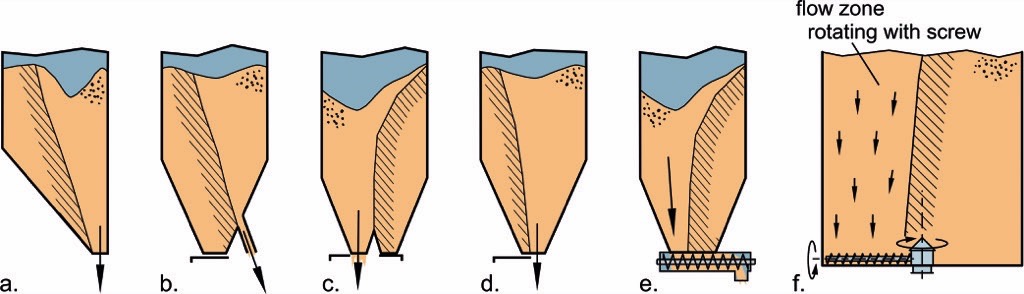
The distribution of the wall normal stress resulting from eccentric flow is schematically depicted in Fig. 27.b. In the region of the flow zone significantly lower wall normal stresses prevail than in the remaining part. On either side of the flow zone slightly larger stresses occur due to the shear stress acting at the boundary between flow zone and stagnant zone.Eccentric flow is funnel flow with an asymmetric flow zone. Asymmetric flow may result from an eccentric outlet opening or an asymmetric hopper (Fig. 28.a), multiple outlet openings which are not discharged simultaneously (Fig. 28.b./c.), not fully opened gates (Fig. 28.d), or a feeder withdrawing the material only from a part of the outlet opening (Fig. 28.e./f.) [1, 2].
The non-uniform stress distributions resulting from eccentric flow are important for structural silo design. Eccentric flow results in loads on the silo walls which would never occur in case of a uniform stress distribution, e.g., bending moments of different orientation [17]. In case of thin-walled cylindrical metal silos the radius of curvature of the cylinder wall is increased in the region of the flow zone (Fig. 27.b), i.e., the wall flattens (similar to slightly pressing a finger on the wall of a thin-walled beverage can). The greater radius of curvature reduces the resistance against buckling due to the vertical compressive stress in the wall. The latter is a result of the support of the bulk solid in the vertical section by shear stresses at the silo wall leading to the situation that a significant part of the bulk solids weight force is acting vertically in the silo wall (refer to Fig. 15 in part 1 [10] of the present paper). Therefore, if eccentric flow is expected, it has to be taken into account at structural silo design. Most silo codes include respective procedures. A silo which is not designed for eccentric flow should definitely neither be operated nor modified in a way that eccentric flow occurs (e. g., by addition of a lateral outlet opening as in Fig. 28. b).If the position of the flow zone changes with time, the stress distribution also changes. The orbiting screw feeder shown in Fig. 28.f rotates with respect to the silo axis. The bulk solid flows from above into the screw and, thus, forms an eccentric flow zone rotating with the screw. Since the rotating flow zone is combined with stresses and deformations as indicated in Fig. 27.b, the silo wall is subjected to alternate bending moments which may be a problem for thick-walled silos (e. g., reinforced concrete silos). The same may happen with other discharge techniques where the position of discharge is moving [18, 19].
Summary of Part 2
In the present second part of the paper on stresses in silos first the processes and stresses in a silo’s hopper were explained. The deformation of the bulk solid at filling or emptying was identified as most decisive process with respect to the stress conditions which were illustrated by Mohr stress circles. The different stress states in the hopper – filling and emptying – result in different stresses at the outlet, and in different loads on the silo walls.Further, disturbances to the stress distribution were discussed. They have to be considered especially for structural silo design. Eccentric flow being a major effect on the stress distribution is included in the European code on silo loads [6].Inserts are not taken into account in the code mentioned above. Here the experience of the structural engineer is very important. Generally, it is recommended to omit any inserts, and if this is not possible, to assess the resulting loads respectfully.
References:
- Schulze, D.: Powders and Bulk Solids; Springer Berlin Heidelberg NewYork Tokyo (2008).
- Schulze, D.: Pulver und Schüttgüter, 3rd. Ed., Springer-Verlag (2014).
- DIN 1055 Teil 6: Lasten in Silozellen; (German code) (1987).
- Kwade. A., D. Schulze, and J. Schwedes: Die direkte Messung des Horizontallastverhältnisses; Beton- und Stahlbetonbau 89 (1994) 3, pp. 58-63 and 89 (1994) 4, pp. 117-119.
- Kwade. A., D. Schulze, and J. Schwedes: Determination of the Stress Ratio in Uniaxial Compression Tests; powder handling & processing 6 (1994) 1, pp. 61-65 and 6 (1994) 2, pp. 199-203.
- EN 1991-4:2006: Eurocode 1: Actions on structures - Part 4: Silos and tanks (2006).
- Janssen, H.A.: Versuche über Getreidedruck in Silozellen; Ztg. Ver. dt. Ing. 39 (1895), pp. 1045–1049.
- Schulze, D.: Die Charakterisierung von Schüttgütern für Siloauslegung und Fließfähigkeitsuntersuchungen (The Characterization of Bulk Solids for Silo Design and Flowability Tests), AT-Aufbereitungstechnik 39 (1998) 2, pp. 47-57.
- Schulze, D., and A. Wittmaier: Flow properties of highly dispersed powders at very small consolidation stresses; Chem. Eng. Technol. 26 (2003) 2, pp. 133-137.
- Schulze, D.: Stresses in Silos – Part 1: Bulk solid properties - Stresses in the vertical section; bulk solids handling 36 (2017) 2, pp. 42-49.
- Schulze, D.: Untersuchungen zur gegenseitigen Beeinflussung von Silo und Austragorgan; PhD Thesis (Dissertation) TU Braunschweig, Germany (1991).
- Schulze, D.: Silo Stress Tool; Program for the assessment of stresses in silos, download at www.dietmar-schulze.de.
- Schulze, D.: The Prediction of Initial Stresses in Hoppers; bulk solids handling 14 (1994) 3, pp. 497-503.
- Schulze, D., and J. Schwedes: An Examination of Initial Stresses in Hoppers; Chem. Engng. Sci. 49 (1994) 13, pp. 2047-2058.
- Strusch, J.: Wandnormalspannungen in einem Silo mit Einbau und Kräfte auf Einbauten; Dissertation, TU Braunschweig, Germany (1996).
- Van Zanten, D.C., and A. Mooij: Bunker Design, Part 2: Wall pressures in mass flow; Journ. of Engng. for Industry, Trans. ASME (1977), pp. 814–818.
- Stiglat, K.: Statisch-konstruktive Bemessung von Silos; Preprints VDI-GVC-Tagung „Agglomerations- und Schüttguttechnik“, Baden-Baden (1991), pp. 109–138.
- Kaldenhoff, M.: Full scale experiences with flow funnel; Proc. Int. Ass. for Shell and Spatial Structures (IASS) Symposium 2009, Valencia (2009), pp. 77–89.
- Lippold, D., and J. Harder: Analysis and design of silo walls; World Cement 35 (2004), pp. 63-68.
| About the Author | |
| Prof. Dr.-Ing. Dietmar Schulze
Prof. Dr.-Ing. Dietmar Schulze, born in 1959, is Professor at the Institute for Recycling of the Ostfalia University of Applied Sciences since 1996. He is co-founder of the consultancy Schwedes + Schulze Schüttguttechnik GmbH (silo design, powder testing) and founder of Dr. Dietmar Schulze Schüttgutmesstechnik (development and manufacture of ring shear testers for powder testing). |
■

