
(From the archive of ”bulk solids handling", article published in Vol. 32 (2012) No. 5 , ©2012 bulk-online.com)
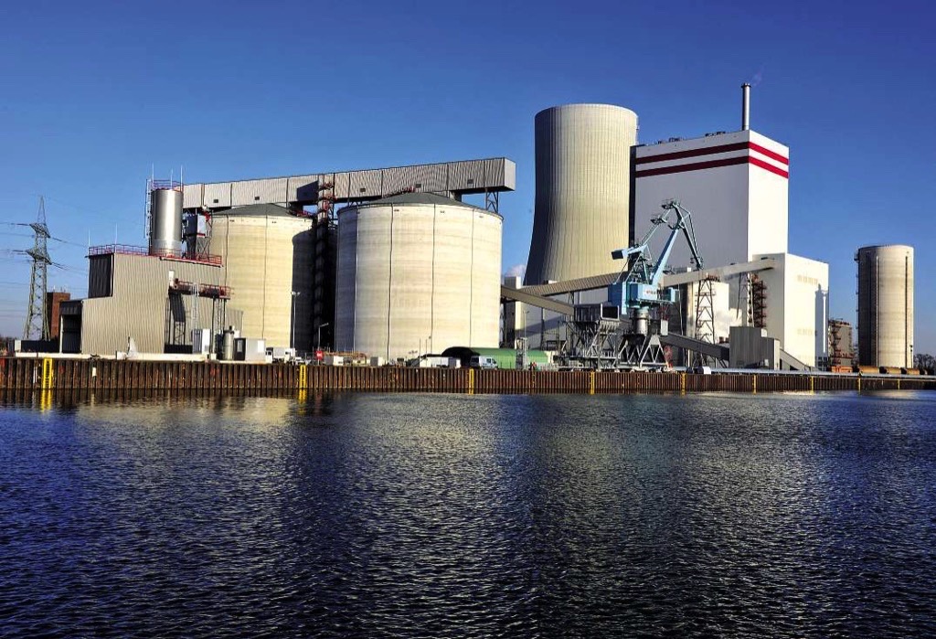
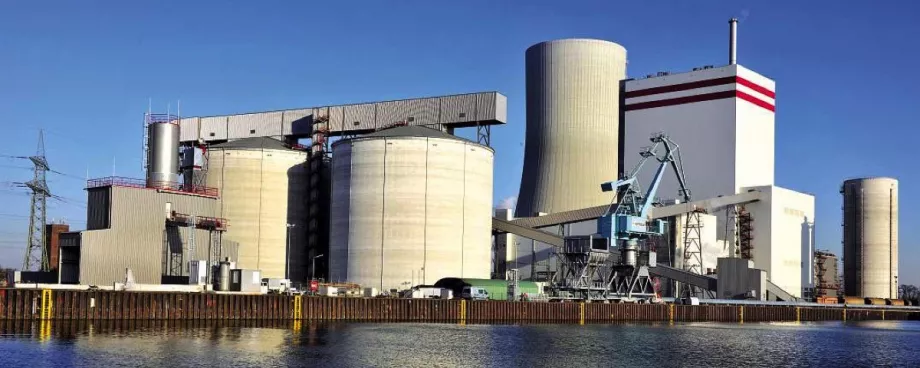
With the limited economic perspective of alternative energy and the hesitance to nuclear power, it is safe to assume that coal based power generation will maintain its prominent position for years to come. Nowadays it is technically possible to design totally enclosed storage and handling systems for storing huge quantities of bulk solids to meet the high demand for energy and mineral resources. The main types of enclosed storage facilities with capacities over 20000 cubic metres will be mentioned schematically. The configurations have not changed but the storage capacity per unit as well as the infeed and outfeed rates have increased strongly during the last decade. On top of that the operating flexibility has been optimised by applying advanced automatic control and monitoring systems.There is a growing number of reasons why organisations which handle and store large quantities of bulk solids like coal, petcoke, wood pellets etc. should care about environmental issues. Not prominent position for years to come. Nowadays it is technically possible to design totally enclosed storage and handling systems for storing huge quantities of bulk solids to meet the high demand for energy and mineral resources. The main types of enclosed storage facilities with capacities over 20000 cubic metres will be mentioned schematically. The configurations have not changed but the storage capacity per unit as well as the infeed and outfeed rates have increased strongly during the last decade. On top of that the operating flexibility has been optimised by applying advanced automatic control and monitoring systems.
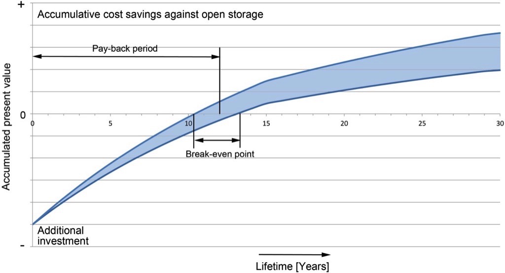
There is a growing number of reasons why organisations which handle and store large quantities of bulk solids like coal, petcoke, wood pellets etc. should care about environmental issues. Not only employees, as internal stakeholders, are affected by pollution in the work environment, but also external stakeholders such as communities are affected by local pollution. Government regulators, investors, environmental activist groups etc. will increasingly put pressure on these organisations to look for new creative and cost-efficient ways to manage and minimise environmental impacts. Following this approach it often appears that the additional investment for an enclosed storage facility will have payback period within approx. the first 10 years of operation.Finally the totally enclosed storage systems are also made possible by the application of the Dutch Eurosilo concept. This proven concept meets the requirements of Environmental Protection Agencies worldwide. The latest developments will be shown.
Main Configurations
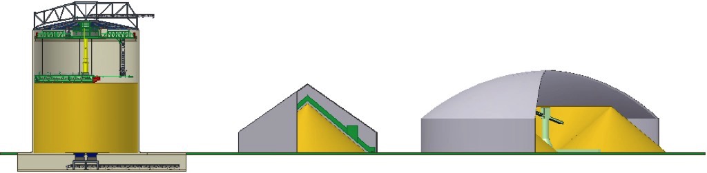
Preventing possible contamination of surrounding land by dust blown off from outside stockpiles, or polluted drain water at the stockyard itself, are major arguments in favour of covered storage. Covered storage also prevents deterioration of material caused by weather conditions such as frost, wind and rain. This is important in order to maintain quality standards, reduce maintenance cost and/or improve operations. Also saving of energy is possible if increased moisture needs to be removed later on.Enclosed storage systems as applied in the bulk handling industry can be divided into three main categories:
- Silo storage, bottom discharge or flat bottom mammoth silo.
- Longitudinal A-frame type storage shed, (covered stockpile)
- Circular (dome) type storage, (covered circular stockpile)
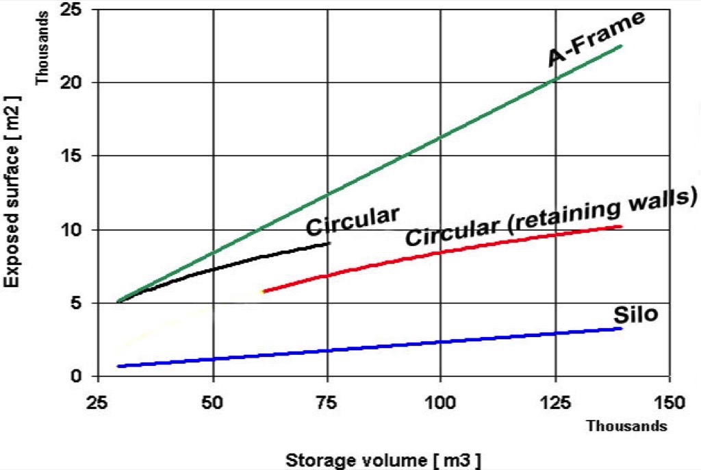
The main differences and equalities between these systems are listed in Table 1.
| Eurosilo | Circular (Dome) storage | Longitudinal (A-frame) storage | |
| Footprint | The most compact system | 2 x larger footprint | 3 x larger footprint |
| Filling (infeed) | Minimal segregation by equalizing auger | Segregation | Segregation |
| Operation | Fully automated | Partly automated | Partly automated |
| Oxygen access | Limited | Severe | Severe |
| Nitrogen purging | Possible through bottom piping | Not possible | Not possible |
| Structure | Simple slip form | Complex concrete wall | Standard A-frame shed |
| Coal monitoring | Continuous monitoring by CO | Only by infrared | Only by infrared |
| Fuel Management | Fully automated | Partly automated | Partly automated |
| Dust emmission | NO | NO | NO |
| Percolation pollution | NO | NO | NO |
Old Arguments
Due to the fact that coal has been a fuel for the power industry for many decades or even centuries, there are still a few old sayings hanging around which are considered as true values for decision makers. Despite the new developments which gave new insights some of them are persistent.
You cannot pile up coal too high!
The original reasoning behind this statement was that the risk of spontaneous combustion is increasing with the storage height. However, the contrary is in fact true. The higher the coal is stored, the more compacted it will become especially in the lower layers which eliminates the oxygen and thus the risk of oxidation. The real reason behind this statement appeared to be very practical, namely in case of open stockpiling which is still the most common method for storing coal, it is complicated to reach the hot spots in higher piles. The last decades coal silos have been built with storage levels of over 70 metres, which are working satisfactorily. So this argument is not valid.
First-in last-out is not acceptable!
Some operators are still convinced that coal is subject to deterioration. This phenomenon might be true for some grades of coal stored in the open air where rain, wind and oxygen have free access to the coal mass. However, in completely sealed silos the lower layers are well compacted and conserved so all the deteriorating factors are eliminated.
Coal silos are "black bombs"!
This argument is based on the fact that there have been a number of accidents with coal and coal dust in silos in the past. Nowadays, the fire safety can be controlled by installing gas detection systems which can measure the smallest oxidation rates so adequate precautions can be taken in an early stage.
Coal silos are too expensive!
For centuries coal has been stored outdoors, and so it goes without saying. The scaling-up of the coal fired units, especially in densely populated areas has made planners and engineers think of ways to store coal under cover. A detailed life cycle approach considering all the costs and benefits learns that the payback period of mammoth silos is attractive relative to the alternatives.
Fire Protection
Enclosed coal storage facilities require special fire protections systems, fires could be caused by self-heating or man-induced. Possible fires can be prevented by organisational, local, technical and constructive measures. Each material, liable to self-heating, has a critical temperature known as the minimum self-ignition temperature. This is the lowest temperature that will create a sustained exothermic reaction (thermal runaway). Hence, if the temperature reaches the minimum self-ignition temperature before the thermal equilibrium is attained then the oxidation process will accelerate. The temperature will escalate rapidly, encouraging even higher rates of oxidation until the material becomes glowing. At this stage, smoke and gaseous products of combustion appear. The dangers of such events are the development of carbon monoxide and the ignition of methane or dust clouds [1].The fire protection system installed in the coal silos built so far, consists mainly out of the following systems:
- Measuring the temperature of the incoming coal by means of an infrared detection section above the infeed conveyor. If the temperature of the exceeds 50°C the operator gets an alarm which results in an intensified monitoring and when the temperature exceeds 70°C the arriving coal should not be stored in the silos but should be conveyed directly to the boiler(s).
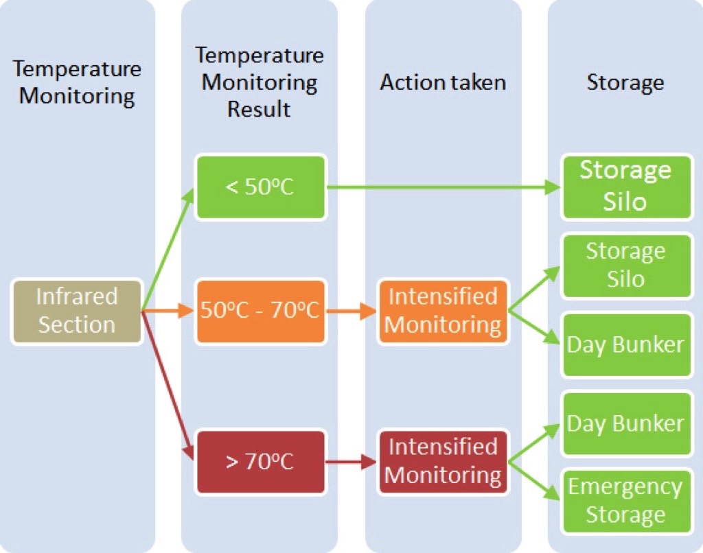 Fig. 4: Temperature decision schedule
 - Inside the coal silos the air is continuously monitored by means of gas detectors measuring CO, O2 and CH4. The CO-concentration is the best indicator to detect the oxidation in an early phase. The O2-concentration controls the accessibility of the silo for operators and the CH4-concentration assures that the atmosphere inside the silo will be kept below the explosion limit. Because the gas detection sensors are also located on the auger frame the top surface is being scanned each round and eventual "hot" spots can be detected.
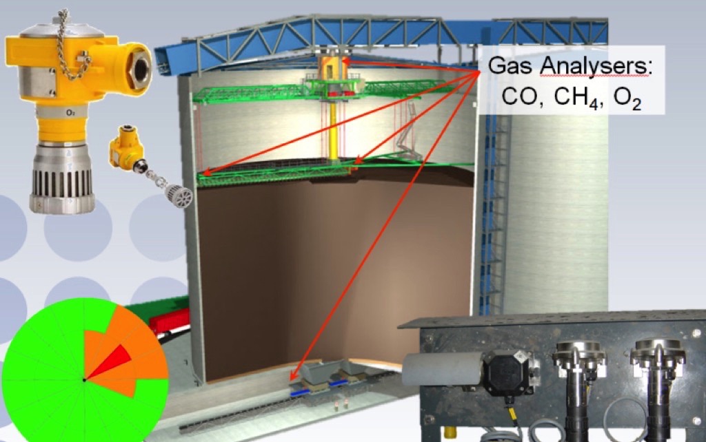 Fig. 5: Gas detection system
 - On the silo bottom there is a layer of granular material in which both the water drainage system as well as the purging piping system is embedded. Through this perforated piping network the coal mass can be purged with nitrogen to drive the oxygen out. This system has approved to be very effective [2].
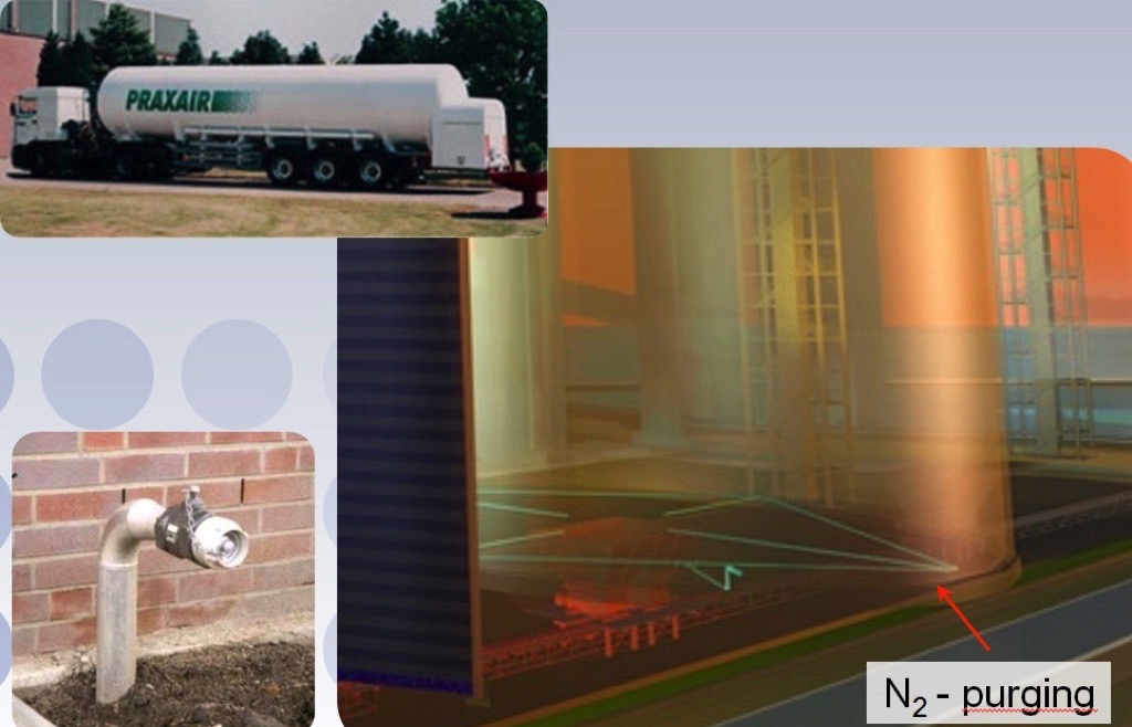 Fig. 6: Nitrogen purging system
 - To minimise the access of oxygen via the coal surface, the top surface can be sprayed with a water-gel or a water-foam mixture forming a sealed blanket on top of the coal mass. Also specific hot spots can be cooled down with the water-gel mixture.

- Fig. 7: Water-gel system
- To cool down the heated coal on the (heat resistant) reclaim conveyor underneath the silo(s) a water spraying system is installed above the belt.
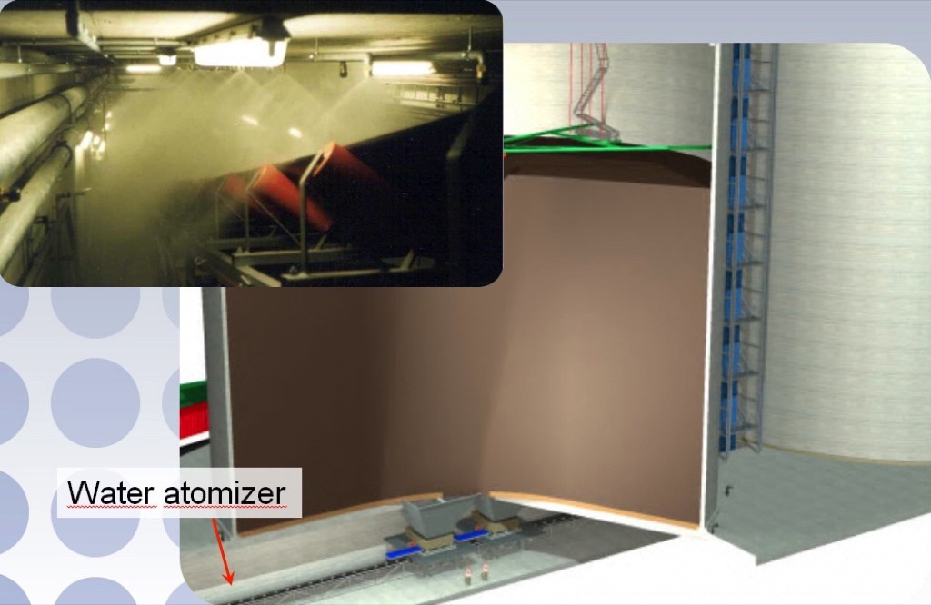 Fig. 8: Water atomiser (cooling) system reclaim conveyor
During the last two decades a lot of experience has been gained with the operation of coal silos at several power plants. Since 1996 the coal silos at the Tiefstack power plant are in operation.Depending on the degree of self-heating, several fire protection measures have been applied successfully to slow down the oxidation process or to convey the coal to the day bunkers at the boiler house. The main objective is to achieve a maximum availability and a minimal downtime of the coal handling system [3].For storing wood pellets a similar system to coal storage silo can be applied. Since the wood pellets have a low moisture, normally around 6 to 8 percent, the tendency for self-hearing is relatively low. The flat top surface of the material which enables the possibility to provide a cover of foam/gel on top is very effective. It also creates the possibility to use a thermal imaging camera to monitor the surface area [4]. Due to the fact that the reactivity of torrified wood pellets is significantly lower than the other fuels the large scale storage silos are well suited for storing this type of upcoming fuel as well.
Life Cycle Approach
One of the methods to integrate the environmental, operational and maintenance issues into a financial evaluation is the EMA method [5]. Environmental Management Accounting (EMA) put the focus on both physical information concerning stored bulk materials like air emissions, risk of self combustion, drain water, waste etc., and the monetary information on related costs and earnings. With EMA it is possible to convert all financial accounting cost data into useful information in order to increase material efficiency, energy efficiency, etc., and to reduce environmental impacts and costs. To ensure an organisation's long-term competitiveness it is vital to achieve cost-effective compliance with environmental regulations and self-imposed environmental policies. Following this approach, the investment in mammoth silos comes with a payback period of just 10 to 15 years.
Main Silo System Components
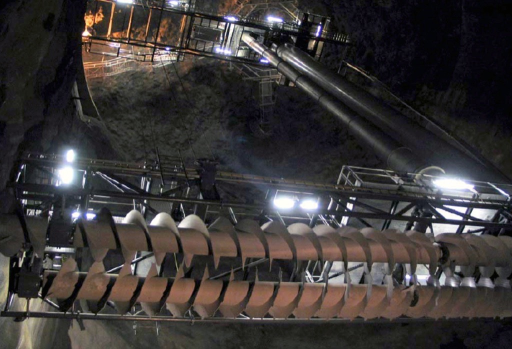
The Eurosilo system for coal storage consists of a concrete slip-formed silo shell, ranging from 30 up to 70 metres in diameter. The storage height varies from 30 up to 50 metres, depending on the soil conditions. The silo building is erected on a concrete foundation including a concrete reclaim runnel and is covered by a structural steel roof. The roof gallery houses the in-feed conveyor. The bulk solid is transferred into the silo through the transfer chute at the end of this infeed conveyor.The central structure forms the connection between the static roof gallery and the slewing silo mechanism. The central slewing piece is a steel structure, which is suspended from the roof gallery through a slewing bearing. The slip-ring body creates the electrical connection for power supply and signals. The auger frame is suspended by steel wires from the rotating bridge and central structure. The auger frame can be lifted and lowered by a winch system. To guide the incoming bulk material to the augers of the auger frame a telescopic chute is integrated in the central structure. The telescopic chute adjusts to the variable height between the bridge and the auger frame.The rotating double-sided bridge is centrally mounted on the central slewing piece and supported at the wall by wheels on a crane track. The bridge is a welded steel structure, and is driven by two slewing drive units, each consisting of two frequency-controlled drives to drive the wheels on the crane track.The auger frame is a welded construction, suspended from the bridge and central part by steel wire ropes. The frame is guided by wheels on de silo wall. Underneath this structure two steel augers are mounted. The optimal configuration of the screw conveyor design is a consequence of the relationship between screw diameter and silo diameter. The augers convey the bulk-solids from the centre to the wall and vice versa. By the slewing of the auger frame the bulk solids are evenly spread out over the bulk solid surface. After each complete rotation, the auger frame is raised by the winches to fill the silo layer by layer until the coal reaches its maximum level or when reclaiming commences.
Reclaiming Process and Fuel Management
The reclaiming capacity of a Eurosilo may vary up to 2000 tonnes per hour. To ensure a continuous and uninterrupted fuel flow to the day bunkers, each silo has two ( one redundant) reclaimers. In case of the uncoaler type, reclaimers are a combination of pile activators and vibratory feeders in one machine. Electrically powered eccentric counterweights or exciters provide the necessary force to induce gravity flow in the centre and to discharge the coal onto the reclaiming conveyors. By withdrawal of the coal from the bottom of the silo, a core zone is established. At this point, the auger frame's two screws, located on the surface of the coal, reverse rotation, thus directing the flow of the coal toward, the centre of the silo, continuously feeding the formed core. The upper bridge also rotates in the opposite direction as compared to when loading and with each complete revolution the auger frame is lowered.
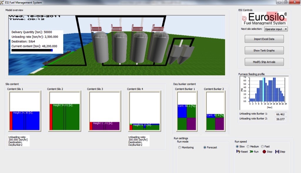
The FMS supports power plant operators with a supply planning and coal silo visualisation for silos which store several grades of coal. The FMS solution is fully integrated with the silo automatisation technology. The FMS software package allows to plan and control the composition of the silo contents. The visualisation provides detail information on coal quality grades and their distribution within the silo. The information can be used to plan ahead based on supply scheduling or to adjust the burning process based on detailed information on present and future fuel input from the silo. This data on the coal flow allows the plant operator to achieve an optimal fuel consumption related to the generating unit performance.
The Helsinki Underground Project
Salmisaari power station is located in the city centre of Helsinki and was built during the fifties in the industrial area. Since then the usage and town planning of this area have changed, so that later predominantly new offices and houses in this area were built and industry has been settled outside Helsinki. Since the power station is in this densely populated environment the environmental issues must be considered particularly. As far as the city council was concerned, they wanted to reserve the largest part of the power station area for offices and houses, because the need and the prices of the properties are high in this area. For these reasons Helsinki Energy received the assignment to realise the coal storage of the power station underground in the rock bottom of this part of the city.
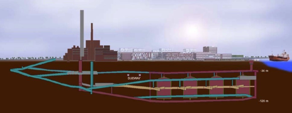
The coal storage consists of four separate storage silos, with diameters of 40 metres and the overall heights being 65 metres. The lowest level of the coal storage is about 120 metres under sea level. With the blasting work a volume of approximately 1 million cubic metres of quarry has been accumulated, which had to be removed through the tunnels. This meant that the transportation of rock took place in three shifts during peak periods, a truck every 6 minutes.Fire protection regulations have a high priority and require special measures during the realisation of the underground project.
The usage of combustible material had to be minimised in the Salmisaari coal storage and e. g. asphalt was not certified to be applied as floor material. Instead of asphalt, concrete is used. Fire monitoring and fire extinguishers need special measures. Water as a fire extinguisher is not allowed within the silo ranges, as its substitute nitrogen has to be applied. In other units water and water networks are used. The coal storage is also equipped with video cameras and monitoring devices of the hazardous gases (like radon, CO and methane CHJ In the underground areas light and telephone connections are extremely important. Separate telephone networks for normal operations and fire-brigade purposes were installed.The basic principle for storing and reclaiming the coal in the underground silo's is the same as for normal coal silos. The only auger frame could not be guided on these walls. Therefore a steel column has been installed. The position of this column inside the coal heap is constantly monitored and, if needed, adjusted with the twin uncoaler system.
Conclusion
To avoid any costly surprise during the start-up of a storage facility the flow characteristics of the bulk solids as well as the chemical characteristics should be investigated thoroughly. For example the wide range of bio mass to be handled nowadays, has already caused a lot of trouble because of the brash and thoughtless design approach.During the early design or even planning stage a wide range of design criteria should be considered by a multi-disciplinary team and quantified in a Life Cycle Assessment model. Hereto the Environmental Management Accounting method (EMA) could be introduced within the bulk material handling industry. EMA helps to gain insight in and forces to quantify the (unaccounted) losses of material and energy, [6].
A Note from the Editor
For all statements in this article that refer – directly or indirectly – to the time of publication (for example “new”, “now”, “present”, but also expressions such as “patent pending”), please keep in mind that this article was originally published in 2012.
References:
- Nijhof, H. H.: Oxygen access and coal storage. bulk solids handling Vol. 26 (2006) No. 4.
- DMT: Inertisierungstest Kohlesilos Tiefstack. Juli 1997.
- Rosner, C., Röpell, H.: HKW Tiefstack, Hamburg. Vattenfal1 Europe Wärme AG. Erfahrungen mit Silobränden im HKW Tiefstack. VGB Fachtagung 2010.
- Persson, H.: Assessment of fire protection of wood pellet silos. SP Technical Research Institute of Sweden, 2012.
- Jasch, C.: Environmental Management Accounting. Procedures and Principles. New York: United Nations Division for Sustainable Development, Department of Economic and Social Affairs, 2001.
- Schott, D. L., Maan, O. C., Spaargaren, R., Ruijgrok, J., Welink, J. -H., Dekkers, J. A. J. M.: Environmental Management Accounting as a selection tool for storage systems. Paper presented at BulkEurope 2008 in Prague.
| About the Author | |
| Jaap P. J. RuijgrokManaging DirectorESI Eurosilo, The Netherlands |
■

