

Introduction
Every year silos face many problems causing damage and collapse. One of the main reasons of silos failure is the dynamic pressures produced on the silo’s walls during discharge. This pressure is directly related to shape and nature of material flow in silos. Many studies were done on flow shape to determine flow pressures effects on silos walls [4,5,11].
Numerous designs are applied to silos with centric and eccentric discharge [3,7,8], where the last one is to be considered the most used in silos. Some codes deal with the effect of eccentric discharge by adding non-uniform pressures throughout the silo wall or by using over pressure coefficient [1,2]. However, eccentric discharge still needs to be explored in details regarding the location of the discharge outlet which influences both the flow patterns and flow pressure on silo’s wall.Purpose of study: The main goal of this work is to study the flow patterns in cylindrical silos during centric and eccentric discharge, and to measure the dynamic horizontal flow pressure, which is affected by the location of the discharge outlet. For this purpose, a cylindrical prototype silo was designed (see Fig. 1). During this process, all the parameters including silo height, silo width, hopper angle, etc., were considered constants, except for the outlet location, which was changed in order to investigate its effect on the flow pattern and flow pressure exerted on the silos wall.
Experimental Procedure
Preliminary experiments were performed to determine the possible locations of the outlet which has significant effect on flow pattern, flow pressure, and the location of the effective Transition Section (ETS) which produces peak pressures due to the change in flow direction.Experiments were done using a cylindrical metal silo divided in the middle with a plexi-glass plate which allows the flow pattern of material to be observed (Fig. 2, and 3). The location of the flow outlet was changed to produce centric and eccentric discharge cases. To measure the pressure during discharge, pressure cells were distributed at different levels along the height of the silo wall (Fig. 4). Moreover, special pressure measurements were fixed to the wall away and close to the flow outlet. On the other hand, the locations of the Effective Transition Section were covered.
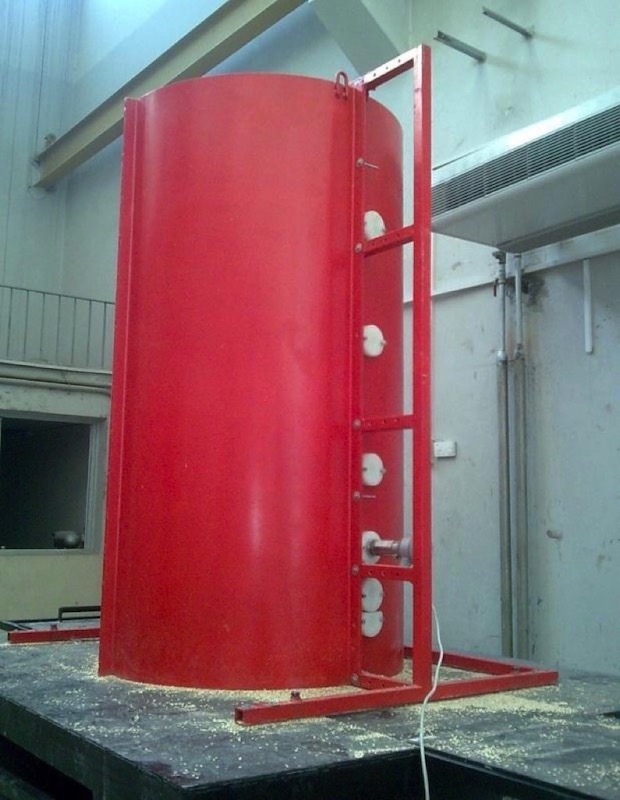 Fig. 2: Study model silo with mounting points of the pressure cells. (Pictures: University of Damacus)
|
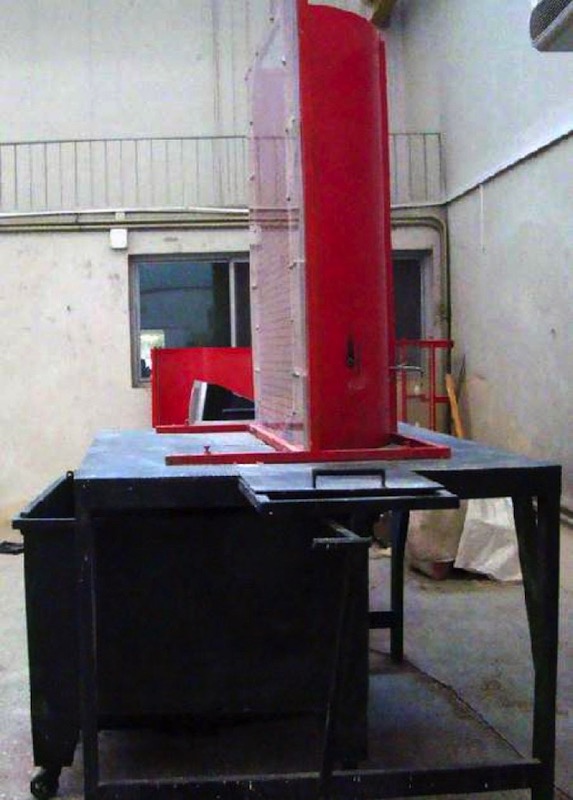 Fig. 3. View of the model silo showing plexiglas front.
|
Fig. 4 shows the dimensions of the modelled silo. The dimensions were selected using physical modelling theory [15]. Metal was used due to its smooth surface, which reduces the effect of ”angle of friction” on the silo wall [12]. Angle of friction may alter the shape of particles flow and the flow pressure.
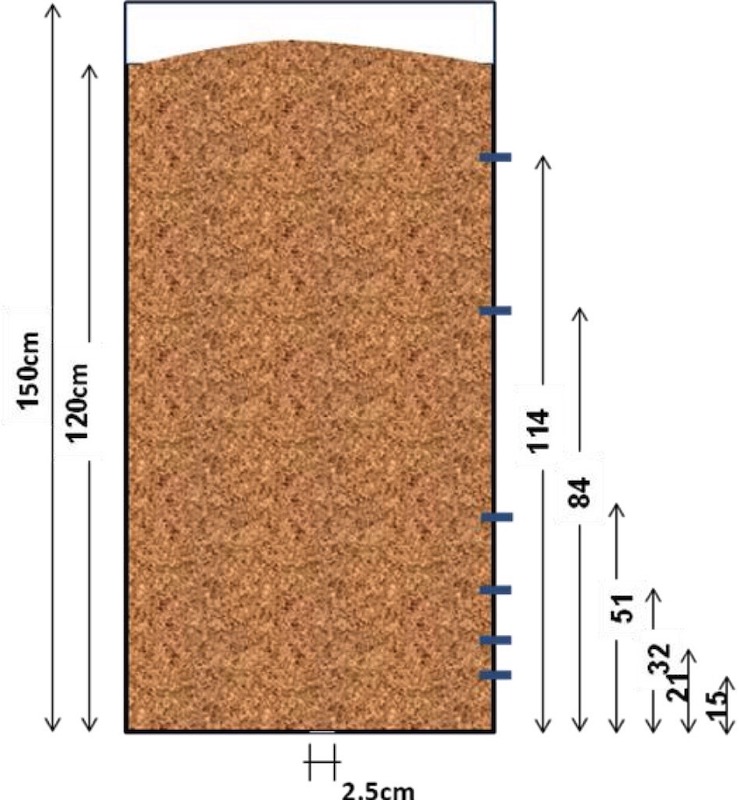
Previous studies also indicated that the internal angle of friction must be the same in both prototype and real silo [12,13], or at least the difference must be no more than 5 degree which has been considered in this research. The size of the corn particles used in this experiments was chosen to be smaller than normal with the aim of preventing particles from interlocking, which could provide a flow obstruction. However, very small particles were also not used as they may accumulate and cause lumping in flow.The data of the pressure measurement cells mounted on the silo were collected digitally and saved into a computer station. Also, all the experiments were carried out under similar experimental conditions using centric and eccentric discharge. The resulting flow for each case was recorded using video camera.
Flow Observations
It was observed that the flow pattern in centric discharge was symmetric. Flow core was observed in the centre of the silo, while static regions where observed next to the silo wall. In the case of eccentric discharge, it was observed that the flow core has smaller width and it was shifted towards the eccentric outlet, while large static region was formed into opposite side far from the eccentric outletThrough these observations, it was concluded that the effective transition section on the silo wall, proximate to the outlet, moves down towards the silo bottom, while it has moved up on the contrary wall as shown in Figs. 5, 6, and 7.
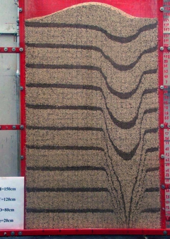 Fig. 5: Centric outlet discharge.
|
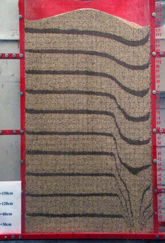 Fig. 6: Eccentric outlet discharge (e/R = 0.5).
|
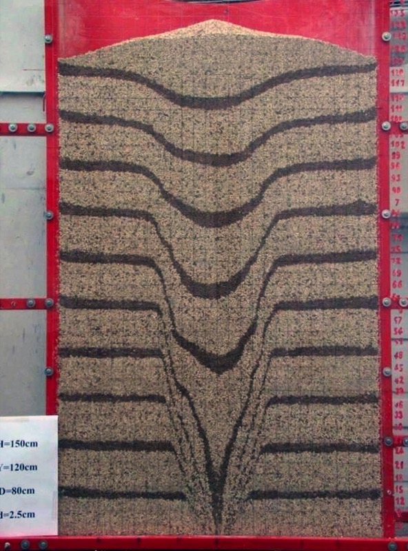 Fig. 7: Eccentric outlet discharge (e/R = 0.75).
|
In the process of evaluating the effect of eccentric outlet, a ratio value equal to the distance between the outlet location and the centre of the silo "e" divided by silo radius "R" (R = 40 centimetre) was introduced to express the eccentric degree of the outlet. During the experiments the materials behaviour for three eccentricities e was investigated (10, 20 and 30 centimetre).
Pressure Measurements
The pressure data collected for the centric operation case of the silo showed that a maximum pressure was recorded at the effective transition section near the bottom of the silo.In the eccentric discharge case and for an eccentric ratio of 0.25, measurements on the proximate wall to the outlet showed that the maximum dynamic pressure was recorded around the region of the effective transition section. On the contrary wall of the silo, measurements demonstrated that the maximum dynamic pressure was at the bottom of the silo, in addition to another rise at the effective transition section. Then, the pressure decreased gradually up to the top of the silo.Repeating the work for eccentric ratios of 0.5 and 0.75, different results were registered where measurements on the proximate wall to the outlet presented that the effective transition section is closer to the bottom of the silo in both cases, with a high pressure produced at this location.On the other hand, a higher dynamic pressure was recorded on this wall at the region of the effective transition section of the contrary wall of the silo. Measurements on the contrary wall of the silo showed that the maximum dynamic pressure occurred at the bottom of the silo.Then, the pressure decreased gradually up to the top of the silo. This result is very similar to the case where the eccentricity ratio equals to 0.25. Figs. 8, 9, 10 and 11 illustrate the distributed pressure produced by each studied case.
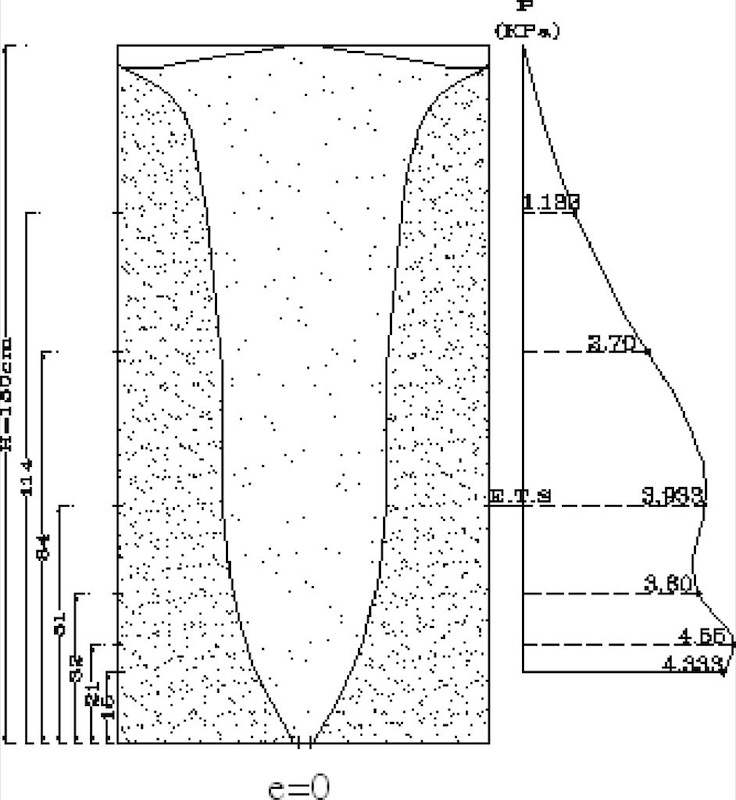 Fig. 8: Centric outlet discharge pressure distribution.
|
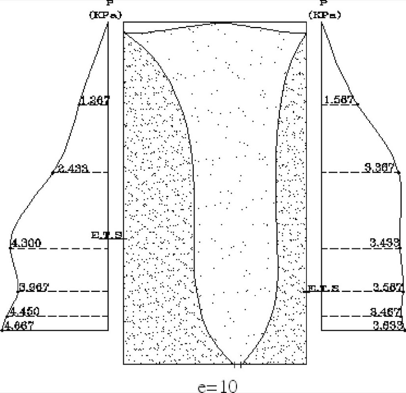 Fig. 9: Eccentric outlet discharge (e/R = 0.25) pressure distribution.
|
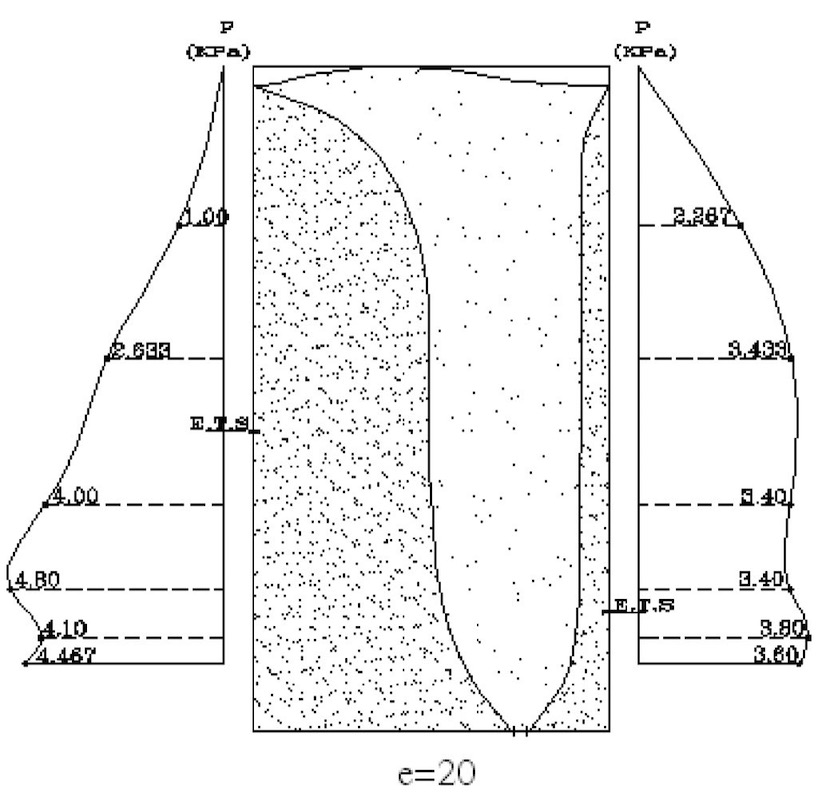 Fig. 10: Eccentric outlet discharge (e/R = 0.5) pressure distribution.
|
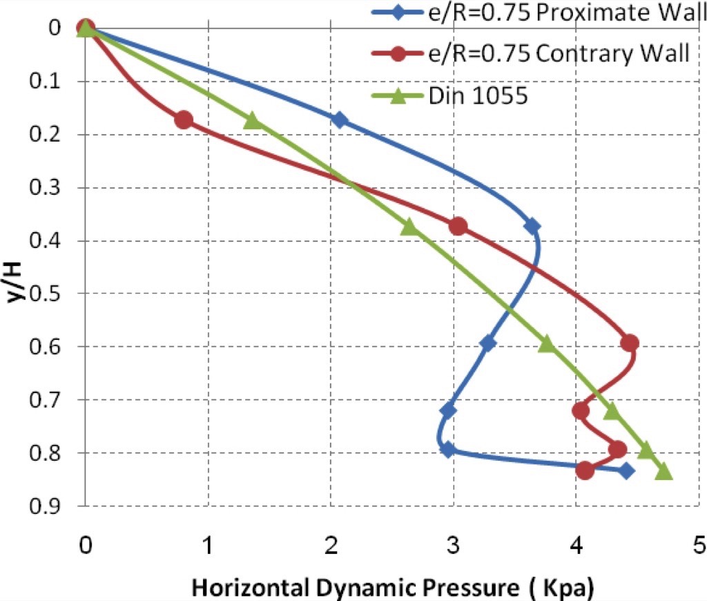
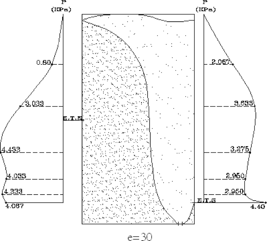 Fig. 11: Eccentric outlet discharge (e/R = 0.75) pressure distribution.
|
Analysis of Results
Figs. 12 and 13 show the values of measured dynamic pressure to wall at each position of measurement cells. All cases related to different eccentric ratios are demonstrated in this figure.It can be seen that the dynamic pressure on the proximate wall has a complex relation to the distance from top. Figs. 12 and 13 demonstrate that the pressure rises in the upper part of the wall proportionally to the eccentric ratio. On the contrary wall, the dynamic pressure drops for the lower part of the wall in an inversely proportionality to the eccentric ratio. However, pressure measurement on the contrary wall does not register much influence by eccentric ratio.
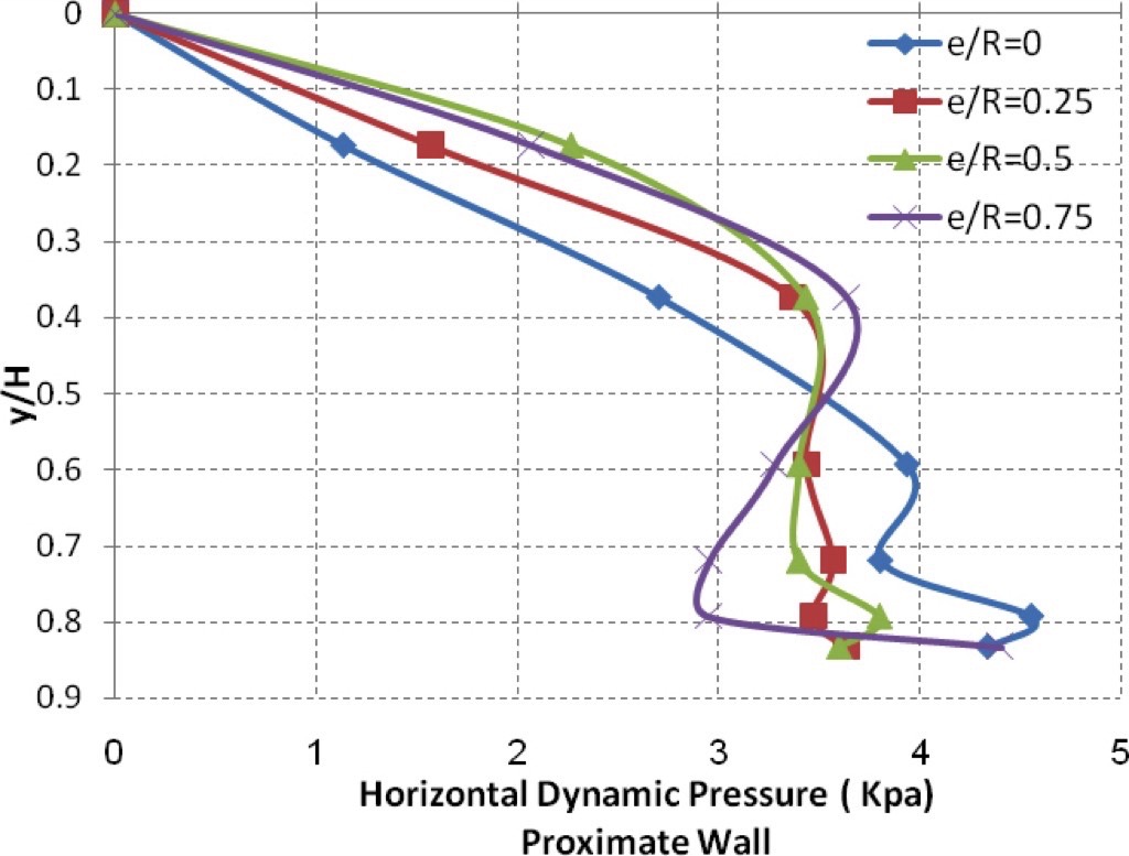
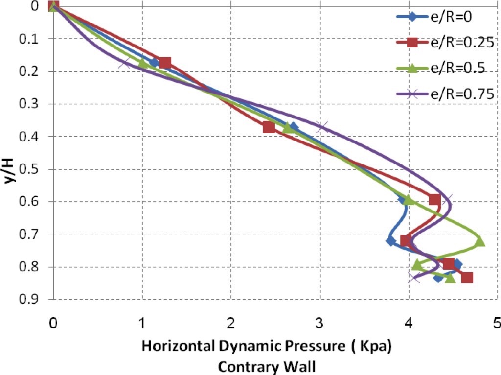
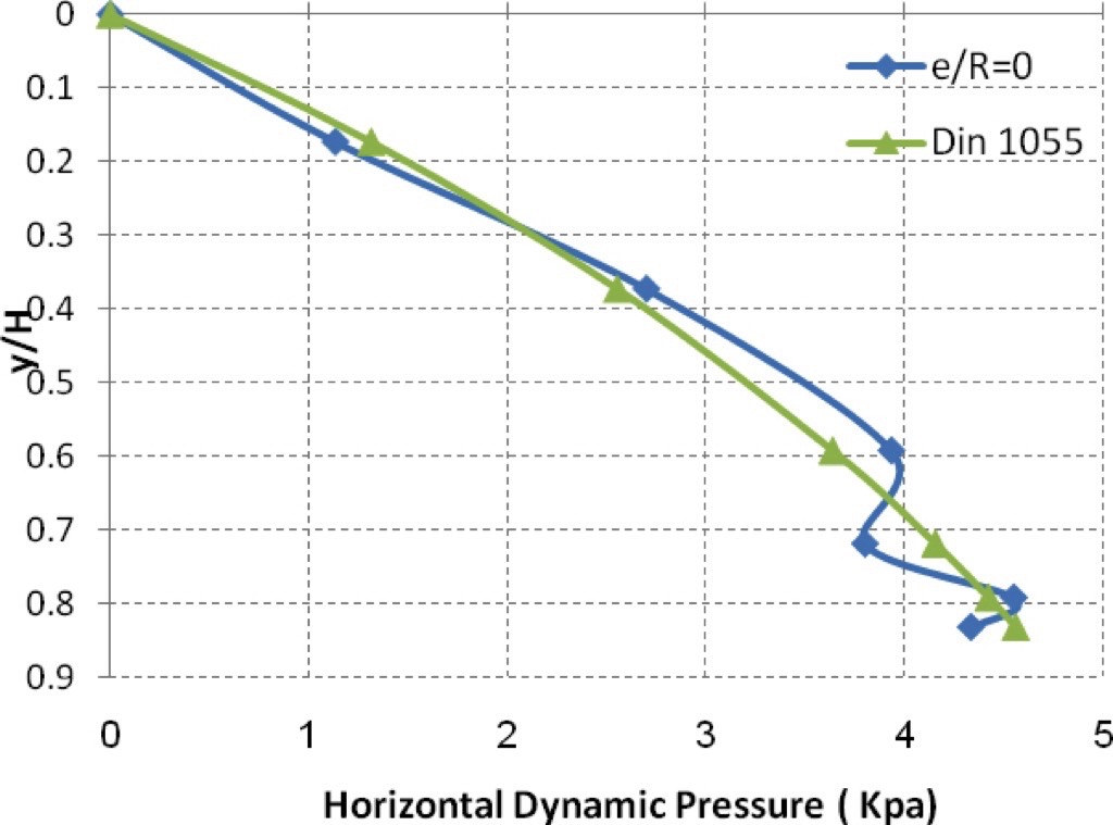
Fig. 14 illustrates a comparison between the experimental data by this study for the dynamic pressure in centric discharge and the values obtained by German Code (Din 1055) where the Figure illustrates a clear match between both results.
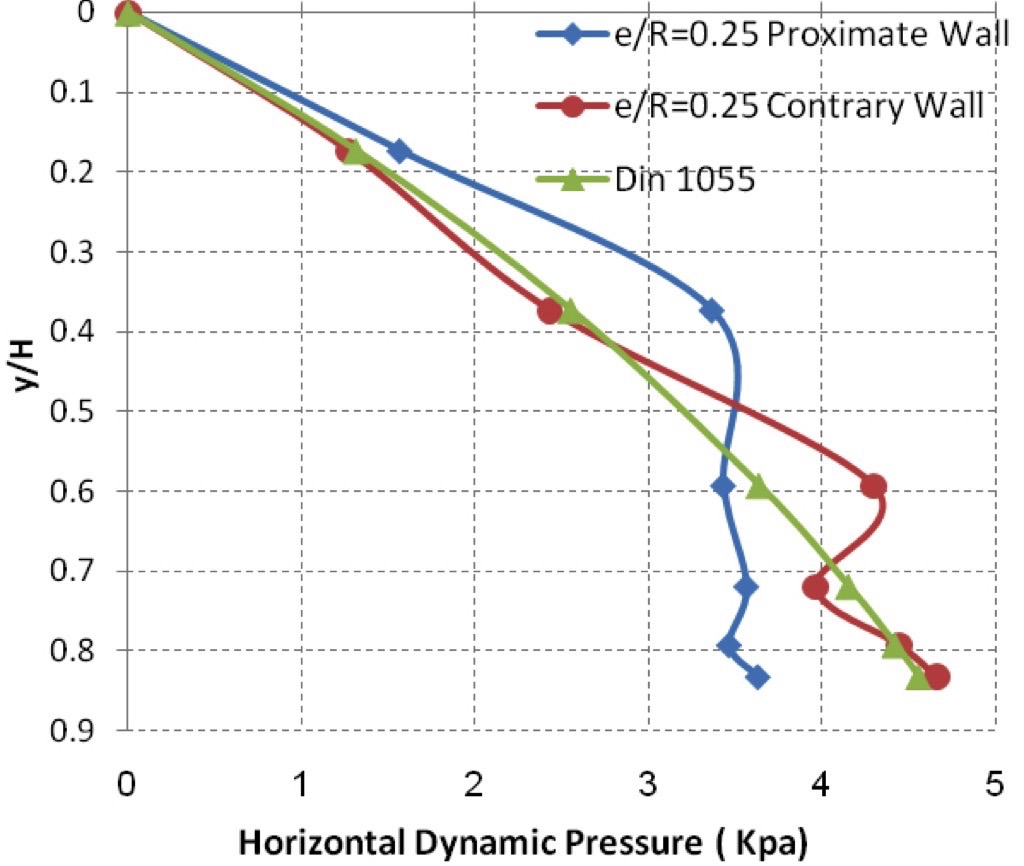
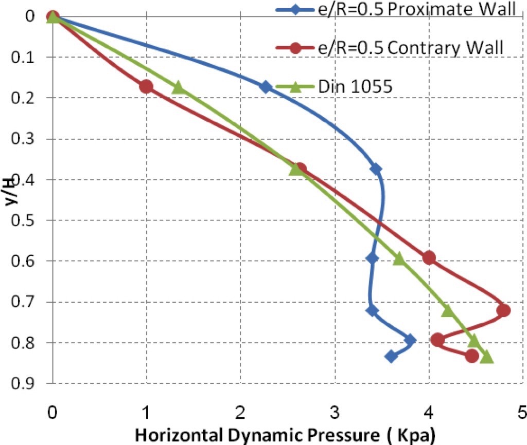
For eccentric discharge, Figs. 15, 16 and 17 compare the dynamic pressure changes along both the proximate wall of the silo and the contrary wall for eccentric ratios 0.25, 0.5 and 0.75 and the designed results derived according to the German code for each of the eccentric cases. It is clear that experimental data of this study matches the results of the German Code for the contrary wall. Whereas, higher dynamic pressure values were recorded experimentally in the higher part of the proximate wall. Based on this observation, it is necessary to take in consideration these high pressure values resulting from eccentric discharge, which has not been covered in codes yet.
Summary of Findings
- The dynamic pressure resulting from eccentric discharge of the silo drops dramatically on the lower part of the proximate wall of the silo in inversely proportionality to the eccentric ratio to reach limits lower than the filling static pressure.
- The dynamic pressure increases dramatically in the upper part of the proximate wall, proportionally to the eccentric ratio.
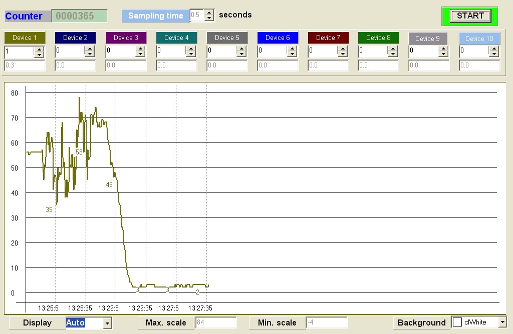
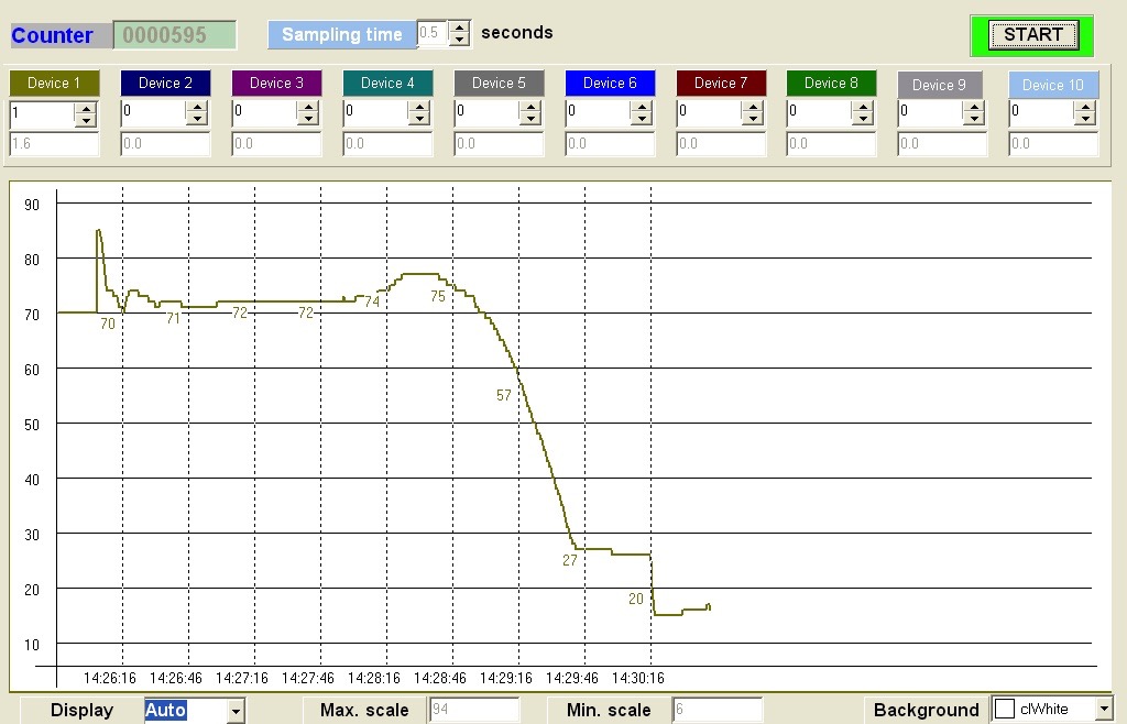
- The dynamic pressure at the proximate wall registers high fluctuations (see Fig. 18), which results in additional bending moment, while no fluctuation was recorded on the contrary wall (see Fig. 19).
- The eccentric ratio has little effect over the dynamic pressure distribution over the contrary wall, and this result agree with previous studies [6].
- The eccentric ratio has very strong effect over the dynamic pressure distribution over the proximate wall.
Conclusion
The present research revealed an important connection between the eccentric outlet location, and the resulting dynamic flow pressure, because of a significant high pressure that recorded for the biggest eccentric ratio especially in the upper part of the silo, so it is very important to pay more attention to the design of the upper part of the silo in eccentric discharge cases due to the high dynamic pressure recorded in these cases.Moreover In design procedure, it is necessary to consider the fluctuation in the dynamic pressure over the proximate wall and its relation to the eccentric ratio and the resulting bending moment.
A Note from the Editor
For all statements in this article that refer – directly or indirectly – to the time of publication (for example “new”, “now”, “present”, but also expressions such as “patent pending”), please keep in mind that this article was originally published in 2012.
References:
- ACI Committee313: Commentary on standard practice for design and construction of concrete silos and stacking tubes for storing granular materials. American Concrete institute, Farmington hills, 1997.
- DIN 1055: Design loads for buildings/loads in silo bins. German standards (DIN Normen), 2000.
- Safarian, S.S., Harris, E.C.: Design and construction of silos and bunkers. Van No Strand Reinhold, New York, 1985
- Hammadeh. H.: The effect of silo geometry on the shape of funnel flow and wall pressure of granular material. Ph. D. Thesis, Technical University of Wroclaw, Poland, 1995.
- Carson, J.W., Jenike, A.: Load development and structural considerations in silo design. Jenike and Johanson, Oslo, 1993.
- Khelil, A.: Behavior of cylindrical silos: the structural effect of non-uniform wall pressure. bulk solids handling Vol. 23 (2003) No.5.
- Lewis, J.: Solving powder flow problems in bins and silos. powder and bulk weblog, April 2006.
- Sielamowicz, I., Kowalewski, T.A., Blonski, S.: Central and eccentric granular material flows in bins and hoppers registered by DPIV optical technique. Acta Agrophysica, Poland, 2004.
- Sielamowicz, I., Kowalewski, T.A.: DPIV technique for granular material flows in silo models. 12th International Symposium on Flow Visualization, German Aerospace Center (DLR), September 2006.
- Sielamowicz, I., Mroz, Z., Balevicius, R., Kacianauskas, R.: DEM simulation of wall pressure in a model of silo and comparison to experimental measurements. Partec Conference 2007.
- Ayuga, F, Augado, P., Gallego, E., Ramirez, A.: New steps towards the knowledge of silo behavior. International Agrophysics, Spain, 2005.
- Carson, J.W., Royal, T.A.: Modeling the flow of bulk solids. powder handling and processing Vol. 3. (1991), No. 3.
- Johanson, J.R.: Modeling the flow of bulk solids. Powder Technology Vol. 5, 1971/72.
- Nabeel AL-Shawaf: Studying the compare of silo loads due to international codes. Diploma thesis, 2006.
- Malla, W., Zeno, A., Nahlea, W., Merry, Y.: Applied hydraulic. Damascus University, 2009.
- Ganesan, V., Roesntrater, K.A., Muthukumarappan, K.: Flowability and handling characteristics of bulk solids and powders. Biosystems Engineering 101, 2008.
| About the Author | |
| Dr.-Ing. Hala HammadehAssociate ProfessorFaculty of Civil EngineeringDamaskus University, Syria |
■

