
Introduction
Ideally, the design of a belt conveyor system incorporates a combination of design parameters that minimise energy consumption and lifecycle cost. Too often, conveyor design is driven to minimise capital cost, rather than considering the total cost of ownership. Informed component selection at the design stage can often lead to both a cost effective and energy efficient solution. This paper aims to identify key design parameters for energy efficient conveyor design and assist designers develop more cost effective solutions.
Several authors have investigated the motion resistances of belt conveyors [1-6] while others have specifically investigated methods to minimise energy consumption [7,8,9]. The latter work identified key areas to minimise energy usage with indentation rolling resistance being a major area of interest due to its significant contribution to the overall resistance to motion. Increasing idler roller diameter, specialised belt constructions and low rolling resistance pulley covers were discussed [7]. Furthermore, the energy and cost benefits of increasing idler spacing are well documented [8,9].
While much research has been published on the topic, this paper hopes to add to the literature by demonstrating how data from laboratory tests (covered by a range of standards and handbook methods) can be used effectively in the design process. The approach adopted is to investigate the individual components of the motion resistance, present analytical models to predict each component and, in combination with laboratory test results, demonstrate its application for energy saving conveyor design.
Throughout the paper a number of testing standards and handbook methods are discussed in relation to motion resistance measurement. In some cases, the data obtained from these methods are able to be used directly for conveyor design. However, others only offer a means to compare, and are often not usable directly in the design process, since test parameters are typically different to system specifications. In some cases the results can be modified for design purposes, but must be done so with careful consideration of the fundamental relationships. This paper intends to draw the reader’s attention to these underlying relationships and provide guidance in the application of test data to the design process.
1. Background
During the design of a belt conveyor system, the power demand, take-up tension, and resulting steady state belt tension distribution is calculated for a range of loading conditions. Derivation of the various resistance components varies according to the standard or design method followed, while the slope resistances generally follow the same procedure. For the purpose of this paper, a straight horizontal belt conveyor is assumed, as shown in Fig. 1 which outlines the components of motion resistance for a horizontal belt conveyor.
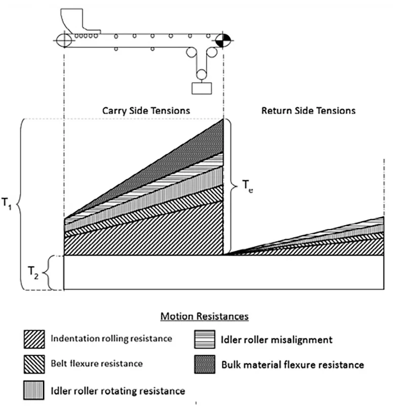
These resistance components are notably different to those in DIN 22101 [10] and ISO 5048 [11] but similar to those referenced in CEMA [12]. The resistance components take into consideration individual contributions, rather than adding multiple resistances together. The motion resistance components include indentation rolling resistance, belt flexure resistance, idler roller rotating resistance, idler roller misalignment resistance and bulk material flexure resistance. Like DIN and ISO standards, the cumulative resistance along the length of the belt conveyor is calculated by superimposing the contributions from each of the motion resistances, as shown in Fig. 1. Secondary resistance can also be included as a length coefficient based on the approach detailed in DIN or ISO.
With reference to Fig. 1, the belt and bulk material flexure resistance components are shown (due to scaling) to linearly increase with length and therefore independent of tension. In practice, these components do in fact decrease per unit length, as belt tension increases. All other resistance components are considered to be independent of belt tension in the absence of any vertical and horizontal curves.
Each of the main resistance components are discussed in detail, analytical models are presented and, in combination with laboratory test data, trends identified to reduce the motion resistance. For the purpose of this paper the idler roller misalignment resistance will not be discussed, with the reader referred to CEMA [12] for a comprehensive treatment of this component.
2. Idler Roller Rotating Resistance
The primary function of idler rollers in a belt conveyor system is to support the conveyor belt along its length. Predicting the cumulative resistance of idler rollers is vitally important in calculating the belt tension and therefore power requirements of a system, particularly on long overland conveyors where there are typically more than one thousand idler rollers per kilometre of belt.
The rotating resistance of idler rollers in belt conveyor systems occurs due to the friction of the rolling elements in the bearings, the viscous drag of the lubricant and the friction of the contact lip seals. The resistance force typically contributes between 5 to 15% [6,7] of the motion resistance of long horizontal belt conveyors. While this may be considered a relatively small contribution, when considering belt conveyor systems many kilometres in length, accurately determining this resistance is vital for the appropriate selection of drives and belting.
The rotating resistance of the idler rollers is primarily dependent on the seal type and configuration, the type of bearings, the temperature of the lubricant and the rotational speed of the idler roller. Contact lip seals and grease-filled labyrinth seals typically form the boundary preventing dust and water ingress into the rolling elements of the bearings. The labyrinth seals can be fully packed with grease to optimise the sealing efficiency of the labyrinth, resulting in viscous drag generated from the shearing of the grease between the layers of rotating and stationary surfaces.
An outer contact lip seal typically forms the primary boundary between external contaminants entering the labyrinth seal, while an inner lip seal contains the lubricating grease within the bearing. The outer and inner contact lip seals add to the rotating resistance of the idler roller due to the nature of the sealing mechanism. In addition to the resistances associated with sealing, conventional idler rollers use rolling element bearings where the friction primarily depends on the bearing type and size, the operating speed, the properties and quantity of the lubricant and, to a lesser extent in the case of idler rollers, the load. The total resistance to rotation of a bearing is made up of the rolling and sliding friction between the rolling elements and the cage and guiding surface, and the internal friction of the lubricant [15].
2.1 Experimental Measurement
Several standards exist to measure the rotating resistance of idler rollers [13,14] with the measurement methods recommended in these standards being similar. The SANS method uses a rotating disc positioned directly above the idler roller that in turn drives the roller at 750 rpm and applies a 250 N vertical load at a temperature of 20°C. The shaft of the idler roller is supported on a pivot which is restricted from rotating by a lever arm. Rotating resistance is calculated from the moment determined from the length of the lever and the force acting at the end of the lever arm. Figs. 2 and 3 show the total rotating resistance and bearing temperature for a Ø152 mm idler roller operating at 6 m/s at ambient temperatures of 20°C and 0°C. Both results clearly demonstrate the reduction in rotating resistance with running time, as the temperature of the grease within the bearings and the labyrinth seals increase.
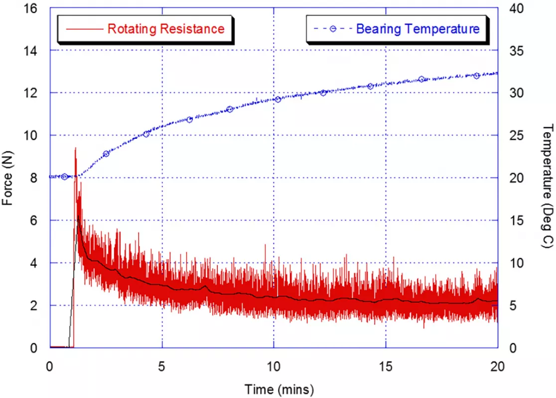
Fig. 2: Idler roller rotating resistance and bearing temperature versus time for a Ø152 mm at 6 m/s at 20 °C ambient temperature
|
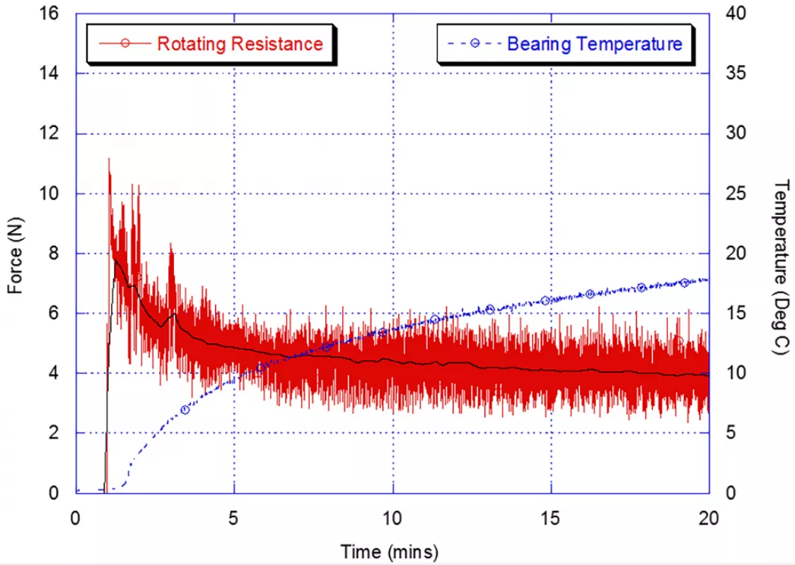
Fig. 3: Idler roller rotating resistance and bearing temperature versus time for a Ø152 mm at 6 m/s at 0 °C ambient temperature
|
2.2 Theoretical Prediction
In order to theoretically predict the rotating resistance of idler rollers, each component that contributes to the resistance is calculated individually. The major components of the rotating resistance that are analysed include the viscous drag due to the shearing of the grease within the labyrinth seal Flab, the friction of the rolling element bearings generated from the no-load and load dependent components Fbrg, and the rotating resistance of the contact lip seals Fls.
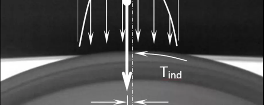
2.2.1 Labyrinth Seal Viscous Drag
![Fig. 4: Typical labyrinth seal configuration and resistance analysis (Picture: ©Wheeler[6])](https://www.bulk-online.com/sites/default/files/public/styles/basic_max/public/2023-12/wp_1261.jpg.webp)
Labyrinth seals consist of a stationary section fitted to the shaft of the idler roller and a rotating part housed into the idler shell. Due to the nature of the sealing mechanism, viscous drag is generated as a result of the shearing of the grease between the layers of rotating and stationary surfaces. The magnitude of the retarding moment depends on the viscosity of the lubricating grease, the rotational speed of the idler roller and physical configuration of the labyrinth seal.
The axial sealing arrangement shown schematically in Fig. 4 may be simplified for analysis by ignoring the end effects of the discs and considering the arrangement as a number of concentric cylinders. In each layer of the labyrinth there is one stationary surface fixed to the shaft and one rotating surface attached to the shell of the idler roller. Fig. 4 also shows schematically the simplified analysis and details the force balance at the interface between the seal and grease.
Mlab is the moment acting due to the viscous drag of the labyrinth seal, Ω is the angular velocity of the idler roller and τ is the shear stress acting on an element of grease. The subscripts represent the concentric surfaces labelled from the centre outwards.
Grease may be considered a Newtonian fluid under normal operating conditions, with the force momentum balance for one-dimensional planar flow given by

|
The shear stress τyx acting on the fluid element is subjected to a shear rate du/dy, where u is the velocity of the grease and y the position. The constant of proportionality is the absolute, or dynamic viscosity, μ. Provided the dynamic viscosity of the lubricating grease is constant throughout the labyrinth seal, the total moment acting due to the viscous drag is
|
where n is the number of concentric labyrinth surfaces. The resistance force per idler roller acting as a result of the resistance of the labyrinth seals is then given by

|
where D is the diameter of the idler roller.
2.2.2 Ball and Roller Bearing Friction
Bearing friction in ball and roller bearings is generated due to the hysteresis formed within the contact zone. Conveyor idler roller bearings are generally grease lubricated due to the relatively low operating speeds and the ability to pre-pack the bearings for extended service life. The grease lubricant acts as a load transmitting element that prevents metal-to-metal contact between the rolling elements and, as such, the rolling elements experience a combination of hydrodynamic and boundary lubrication. The total friction moment for a bearing within an idler roller is determined from the sum of the no-load and load dependent moments. The frictional losses associated with grease lubricated bearings under no-load conditions are difficult to predict accurately, however an approximation of the no-load friction moment M0 is given by Palmgren [15] as

|
Provided

|
where ν is the kinematic viscosity of the grease, s is the speed of rotation of the bearing and the relationship between the dynamic viscosity μ, and the kinematic viscosity ν, is

|
where ρ is the density of the grease. The kinematic viscosity is also known as the base oil viscosity and is normally expressed in cSt, where 1 cSt = 1·10-6 m2/s.
Additionally, dm is the mean diameter of the bearing represented by

|
where di is the inside diameter and do is the outside diameter of the bearing. Furthermore ƒ0 in Eq. (4) is a factor depending on the bearing design and lubrication method, where ƒ0 = 1.5 to 2.0 for single row deep groove ball bearings.
A load dependent friction moment M1, due to the sliding resistance and hysteresis resistance of the bearing elements, is given by Palmgren [15] as

|
where Fr is the radial component of dynamic bearing load. The load dependent friction factor ƒ1, for 62-series deep groove ball bearings is given by
|
and for 63-series deep groove ball bearings by
|
where C0 is the static load rating of the bearing given by the manufacturer and X0 is the radial factor, depending on the bearing design. X0 = 0.6 for single row deep groove ball bearings. The total friction moment of each bearing Mbrg may be obtained by adding the no-load moment M0 and the load dependent moment M1 giving

|
The resistance force per idler roller acting due to the rolling element resistance of the bearings Fbrg is then given by

|
2.2.3 Lip Seal Resistance
The outer lip seal forms the primary boundary between external contaminants entering the labyrinth seal, while the inner lip seal (if present) contains the lubricating grease within the bearing. Most lip seals used in idler rollers are made from nitrile rubber or similar compounds. The outer lip seals are typically fixed to the shaft and rub against the external surface of the labyrinth seal without any lubrication, while the design of the inner lip seal varies significantly between manufacturers. In order to approximate the resistance to rotation due to the lip seals, the following equation is derived from a graphical representation of the power loss for contact lip seals [16]. The force acting due to the resistance to rotation of the lip seal Fls, is approximated by
|
where dls is the contact diameter of the lip seal. Eq. (13) should only be considered an approximation due to the large variety of lip seal designs and configurations employed, in addition to the absence of any temperature correction factor, or allowance for dry or lubricated contact surfaces.
