
(From the archive of ”bulk solids handling", article published in Vol. 32 (2012) No. 4 , ©2012 bulk-online.com)
One of the disadvantages of using bends in pneumatic conveyors is the wear of the bends, if the material being conveyed is at all abrasive e.g. if the particles are hard and angular such as minerals, coal, ash etc. Wear also often occurs in long straight sections just after pipe joints. This wear problem is often very costly, resulting in many unplanned stoppages for repair on systems conveying these materials, as well as producing severe mess from leakage of the material after a puncture.There are many different means of providing wear protection for bends and straight pipe sections, but they too can be costly, with the best wear resistant materials costing as much as USD 5000 per bend or even more to apply; and the wrong choice can lead to much wasted money if it does not give the protection hoped for. Other wear resistant solutions can severely increase the energy consumption of the conveyor, or limit its throughput, if applied too liberally. Hence it is very important to choose carefully the right means of wear protection. This article will review the common sites and causes of conveying pipeline wear, and show that with the latest technology for characterising the erosiveness of the conveyed material, it is possible to choose a wear protection solution that will give cost-effective protection.
The Problems
Wear in pipelines is undesirable because it usually gives rise to:
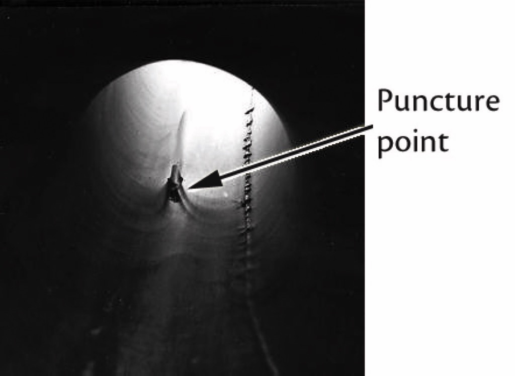
- Mess arising from spillage of material through punctures in pipes.
- Unplanned maintenance in replacing bends and pipeline components.
- Downtime on process (this is usually the biggest cost by far).
- Contamination of transported product with wear particles (usually iron, which causes “yellowing” of white materials).
The occurrence of this problem of wear in pneumatic conveying has historically been so common that it has put some users off this form of transport, or at least earned it a bad reputation. In recent years, however, the understanding of the causes of the problem, and the consequent development of techniques to overcome it, has progressed very greatly to the point where it is now possible to convey economically materials which would previously have caused too many wear problems.
The Main Issue
The main mechanism of pipeline wear is the collisions between particles and pipe wall, especially at bends. As a particle approaches a bend, it is travelling at almost the same velocity as the air, but once it enters the bend it tends to go in a straight line and collide with the outer wall of the bend, whereas the air is deflected around the bend. This is purely due to the inertia of the particle, and the particles have to be very small (a handful of microns) to follow the air flow instead of colliding with the bend wall.The resulting damage to the pipe surface is dependent on a number of factors, as follows.
The Role of Velocity
One of the main keys to mitigating wear, is to understand the effect of particle velocity, which is of course closely related to air velocity. The energy expended in a collision is a direct function of the velocity beforehand. Consequently, wear of the pipe surface increases with increasing particle impact velocity. This relates directly to the deceleration forces experienced by the particles when impacting against pipeline bends, misalignments etc.The degree of wear depends on the mechanical properties, shape and size of the particles and the mechanical properties and geometry of the pipe wall. However, the general trend is well documented:Erosion = k · (particle velocity)nwhere k is a constant and n is a power usually between 2.2 and 2.8 for most materials. Such an equation is often used to model the rate of wear [1], showing that for example a 25 percent increase in particle velocity will give rise to something between a 60 and 90 percent increase in rate of wear.Given this type of relationship, the primary strategy for minimising the wear has to be one of reducing particle velocity as far as possible – even small reductions in velocity will always bring big reductions in the problem.
Dilute and Dense Phase Conveying
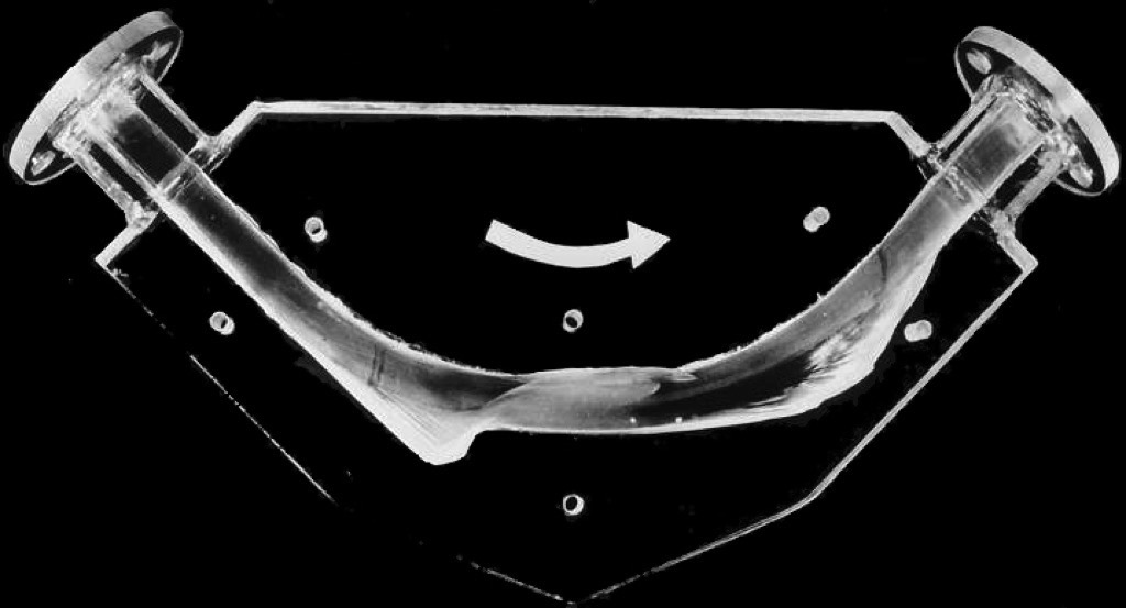
The traditional form of pneumatic conveying is where the particles are conveyed through the pipeline in suspension in the carrier gas at relatively high velocities, Fig 4 (i). This method of conveying is known variously as dilute phase, lean phase or suspension conveying. To keep the particles in suspension requires high air velocities, typically in the range 14 to 20 metres per second minimum, depending on the particles and the pipe size.
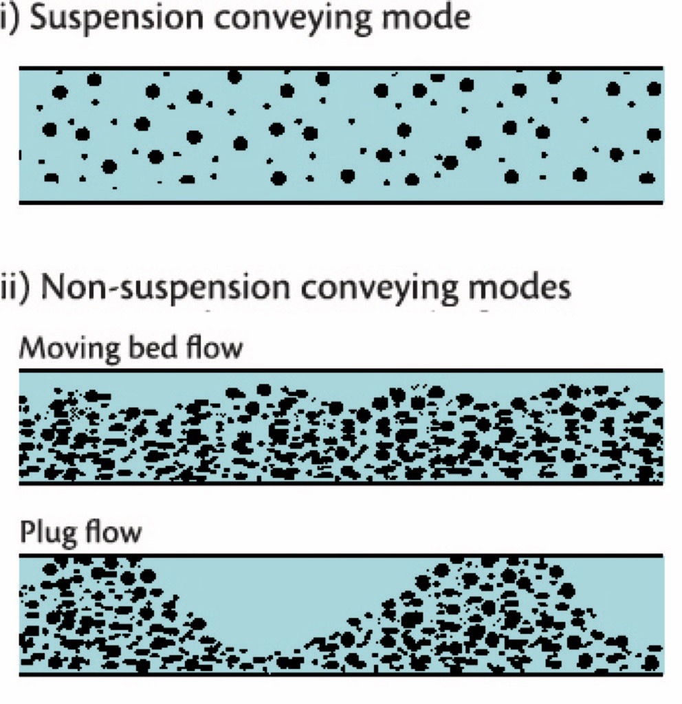
However, with some materials it is possible to convey them at lower velocities than those needed for suspension flow. The mechanism by which such materials can be conveyed through a pipeline depends on the physical characteristics of the product in question, but typically is in the form of a moving bed or a slugging flow at high concentrations in the air, e.g. Fig 4 (ii). Typical air velocities would be only 2 to 6 metres per second at the material feed point. This approach is commonly known as dense phase or non-suspension conveying. The combination of lower velocities and the fact that the majority of the particles are mutually self supported by their immediate neighbours, thereby preventing contact with the pipeline walls, means that a well designed system operating on this basis can result in a major reduction in pipeline wear compared with that of a dilute phase system operating at the same duty.Hence the dense phase approach has major attractions in overcoming the problem we are trying to address. However, it should be recognised that whilst it is possible to convey virtually any material in a dilute phase mode, this is not the case with dense phase – many materials will simply block the pipe if the air velocity is not sufficient for suspension flow. Various bench type tests have been developed at The Wolfson Centre for assessing whether a product will convey in a dense phase mode [2], but the only really reliable method of making this assessment is to subject a representative sample of the product to a conveying trial in a pilot size pneumatic conveyor. This approach also has the advantage that it enables the level of wear resulting from conveying at various conditions to be evaluated, as well as permitting the information necessary to the successful design and operation of such systems to be determined [1].For those not familiar with pneumatic conveying it should be recognised that pipeline bores and associated hardware for systems operating at the same duty but in dilute or dense phase modes are likely to be quite different. A dense phase system is likely to be built around a high pressure blow tank feeder operating on a batch-wise basis. With this in mind care should be taken to avoid the tank at high pressure rapidly venting down the pipeline at the end of the conveying cycle. It is known that the very high air velocities present in this phase of the cycle can lead to very high wear.It should also be realised that the conveying line pressure drop for dense phase transport can be much higher than those in a corresponding dilute phase system, e.g. 2 to 6 bar compared with 0.5 to 1 bar. Consequently, the significantly higher expansion effects in a dense phase system means that towards the end of the conveying pipeline the air and particle velocities may be of the same order as a lean phase system operating at the same duty. Irrespective of the type of system under consideration it is possible to control air velocities and therefore particle velocities within certain limits by the technique described in the next section.
Stepped Bore Pipelines
Increasing the bore of the conveying pipeline at strategic points along its length is an effective way of controlling the air velocities in the pipeline. As the conveying air flows along the pipeline its pressure decreases and, as a result, the air velocity increases. This is why it is almost always the bend at the end of the system which wears out most often! Increasing the bore of the conveying line at strategic locations along its length allows the air velocities to be kept down, thereby reducing bend and pipeline wear.The positioning of the step to the next available pipe size is crucial if the approach is to operate to maximum effect. If the step in bore is too soon the velocity will be below that for reliable conveying and a blockage is liable to result; conversely, should the step be too far down the pipeline the maximum benefit of the approach in terms of reducing particle velocities and associated attrition and wear will not be fully realised.The advantages to be accrued by this approach will vary from application to application, but a practical design study shown in Figs. 5 and 6 serves well to illustrate the point. This is based on a system with 15 bends, conveying material at 60 tonnes per hour over a pipe run of 60 metres. The design pickup velocity was 11.8 metres per second. In this particular study, the pipeline was feeding to a metallurgical reactor at 1.3 bar gauge, but the same principle applies if the system is exhausting to atmosphere – in fact the effect would be even more marked than in the figures shown.
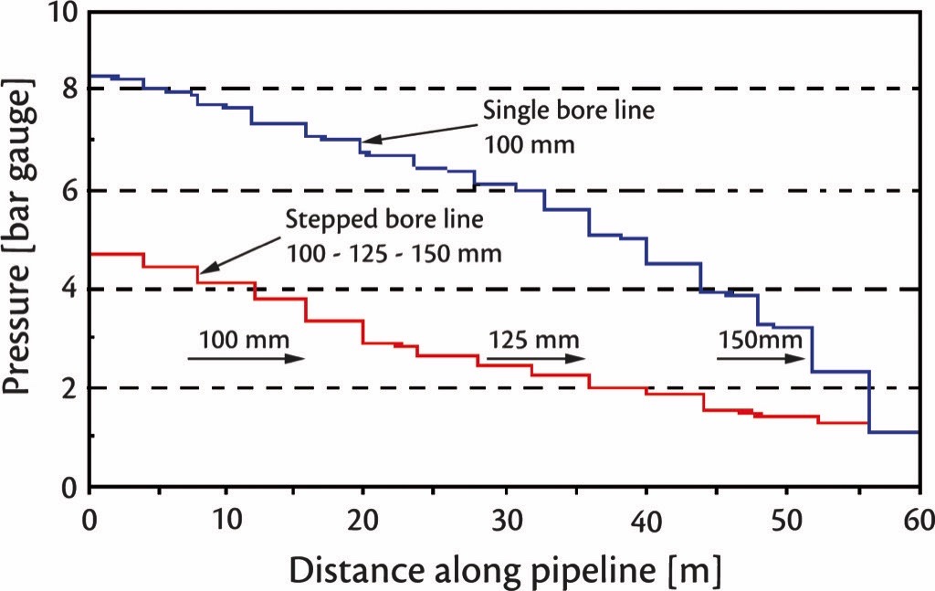
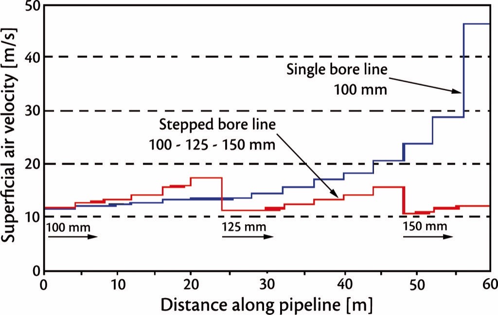
With a pipeline of a single bore size (100 millimetre), the pipeline pressure drop was predicted to be 7 bar, and the outlet air velocity would have been 48 metres per second; whereas if the pipe bore was increased to 125 and then 150 millimetres at appropriate points, the pressure drop reduced to 3.5 bar and the maximum air velocity to 18 metres per second. An air velocity of 48 metres per second would have caused very severe wear of the bends when conveying the abrasive metal concentrate into the reactor; reducing this to 18 metres per second would be expected to yield at least an eight-fold increase in the bend life!This technique has obvious advantages with long distance or dense phase systems, where high pressure drops and hence high outlet air velocities result, however the strong relationship between velocity and both particle attrition and wear means it has considerable merits even for shorter, lower pressure systems. In practice it has been found that where the pressure drop in conveying is more than about 0.4 bar, this is an effective technique.In the past, the major impediment to using stepped bores to maximum effect has been the difficulty in predicting the pressure profile of the conveying air along the pipeline and therefore the optimum position of the step to the next bore. However, a method has more recently been developed that enables the benefits of the approach to be maximised [5].
Pipeline Routings
One of the great advantages of pneumatic conveyors is that they can go around corners without the need for transfer points which would be required for mechanical conveyors. However, this very advantage can become a source of trouble if too many bends are put into a system.The major occurrence of collisions of particles with pipe walls is in bends, as outlined earlier. This is especially true in lean phase systems. Hence it is obvious that the greater the number of bends, the more wearing surfaces there are.However, there is an additional effect, due to the fact that bends contribute a large proportion of the total pressure drop along such a pipeline – as much as 80 or 90 percent of the total pressure drop in many lean phase systems, though the proportion is less in dense phase. More pressure drop along the pipeline means a greater expansion of the air. For any given material we will always need at least a certain minimum air velocity at the pipeline inlet, for successful conveying, so the result of more bends is a higher air velocity towards the outlet end of the pipeline, especially if we do not accommodate it by expanding the pipe bore as outlined above.Consequently, it is well worth doing everything possible to minimise the number of bends in a pipeline, especially in lean phase conveying. Money spent on getting the straightest possible alignment will give a very good return in reduced attrition and wear. In lean phase conveyors, bends close together (less than say five or six metres between their apices) should also be avoided, because to convey reliably through such bends requires an increased air velocity. Likewise, inclined pipelines should always be avoided as these need higher air velocities to operate successfully.
Bend Geometry
Many conveyor suppliers specify only long-radius bends, usually with a ratio of bend radius to pipe bore of about twelve or more. However it is well known that such bends certainly do not give the lowest rate of wear. The “blind tee” bend or commercial equivalents (where the flow is put in along the run of a tee, the far end of which is capped and the flow comes out of the side branch of the tee) invariably give a longer wear life; some people hold that this is the result of the particles filling the “blind” leg of the tee and impacting on each other instead of the steel, although there are other possible explanations.The drawback of using blind tee bends is that they give rise to substantially higher pressure drops, in turn leading to greater air expansion along the pipeline, resulting in higher air velocities and greater wear towards the end of the pipeline. In a system with perhaps just two or three bends they are worth considering, but where there are more than this, blind tees can introduce more problems than they solve. Blind tees should never be used in dense phase conveyors, as the increased pressure drop is far too great when the material is flowing in “slugs”.
Bend Materials
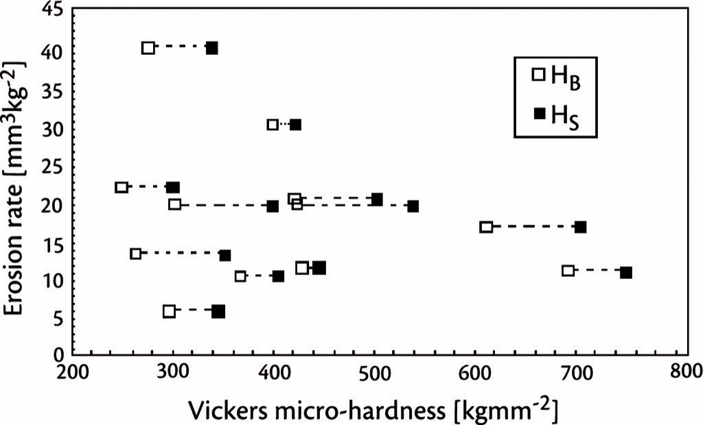
Again as most particle impacts occur in bends, is not unreasonable to propose that the use of rubber bends to absorb some of the energy at impact should go some way to alleviate the problems. This has been known to yield a longer wear life than steel bends where hard, rounded particles are handled. However, where sharp, angular particles are conveyed these can rapidly cut into such bend materials, resulting in a very short service life.The use of hard bend materials to resist wear is well established, and this can be quite effective with some conveyed particles. However, there is at present no general rule to determine the most cost-effective wear-resistant material for an application.Considerable work has been done to investigate what mechanical properties determine the erosion resistance of steels, using the erosion test rig depicted in Fig. 7, and the results have been perhaps surprising; Fig 8 shows the results of a plot of erosion rate of several steels subject to low-angle impact from sand particles, versus steel hardness [5]. The lack of any correlation will be obvious.
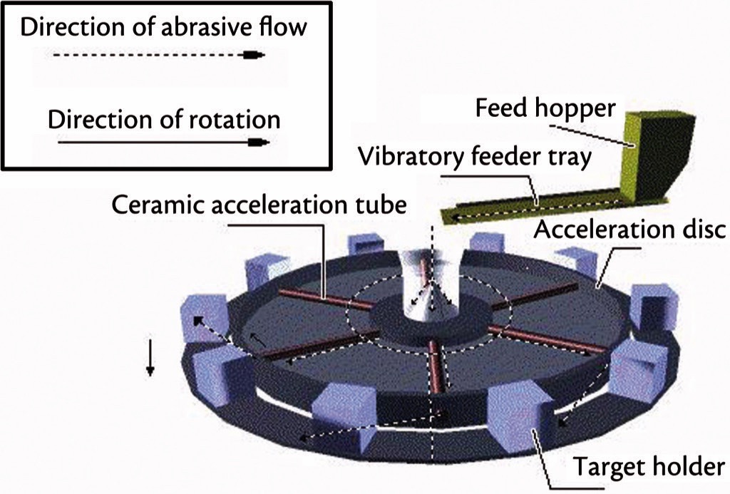
With regard to other wear resistant materials, Fig. 9 shows a plot of measured erosion resistance of five commonly used materials, with again perhaps somewhat surprising results. For example, cast basalt eroded several times faster than mild steel, yet this is often specified for pneumatic conveyor bends – the relative success of this material probably arises more from the fact that it is usually used in sections about six times as thick as steel. Rubber and polyethylene also eroded at high rates compared with mild steel, whereas fused alumina ceramic suffered little erosion.
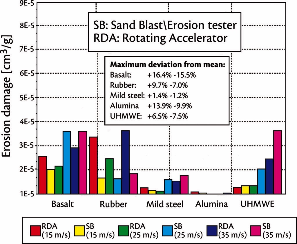
In each of the cases described above and illustrated below, the abrasive material was sand.In the absence of general rules for predicting erosion resistance, the best way of choosing a bend material for minimal operating cost for the time being remains the use of a characterisation test in a rig such as shown in Fig. 7. Testing a number of possible options for the wear resistant bend lining on this rig, under erosive attack from a sample of the bulk solid to be conveyed, will quickly indicate which wear resistant material is an economic choice, and this approach has been used successfully many times at The Wolfson Centre for selecting suitable materials to protect bends in power stations, foundries and other practical applications.
Pipe Fitting
The importance of accurate alignment of pipeline components is often overlooked; yet it is quite common for severe wear to occur just after joints in a long straight pipe, where particles have hit the edge presented by misaligned sections and bounced across to the other side of the pipe, causing wear and eventually puncture. To minimise this it is well worthwhile expending some effort on accurate alignment to avoid such edges against the flow. When using flanged joints, the clearance between flange and pipe o/d, and clearances in the bolt-holes, will make it impossible to ensure truly accurate alignment; in this respect, slip-on strap-clamp type couplings (“Morris” or “Eurac” type couplers) are much better than flanges, as they go straight on to the outside of the pipe and ensure no misalignment of the pipe ends. Using such couplings will often give rise to the need for secure pipe support, as they do not give as positive a location of bends as do flanged joints.
Designs for Minimising Bend Wear
The key points to note for either effect are:
- Use the lowest possible air velocity for reliable flow (this is by far the biggest effect).
- Convey in dense phase if possible (sadly for many materials this is not possible; there is no point in trying to “force” a material to convey in dense phase if it won’t do so reliably).
- Use stepped bore pipelines if the pressure drop is more than about 0.4 bar.
- Minimise the numbers of bends.
- Choose appropriate geometries of bends if this helps with the product in question.
- Undertake an erosion test to choose the best wear resistant material for the bends.
- Ensure correct pipe alignment to eliminate edges against the flow.
- Prevent a blow tank from venting its charge of air along the pipeline as it empties.
Latest Research
Recent efforts in this area have focussed on developing the characterisation side, i.e. improving the accuracy and understanding of the erosion and particle attrition test rigs which are in use to produce “erosiveness” figures for bulk solids against bend materials, and process models i.e. how to use the information to predict the life of the bends in a real system.As a result, there is now available a verified “Bend Wear Prediction Model” that uses measurements from the erosion test rig, together with process conditions from the pipeline design, that can predict the life of bends made of the material tested on the erosion rig.This has been verified against real system tests and found to be sufficiently accurate to lead to the economic choice of wear resistant material. It should be noted that the wear lives of nominally identical bends in systems handling the same bulk solids and operating under the same process conditions, can vary significantly, due to a variety of factor; however, the difference between different wear resistant materials in the same application, is often far greater, so the predictive technique does not have to be especially accurate in pin-pointing the precise bend lifetime, in order to be able to lead the user to the right choice of material that will ultimately give the best economic balance between purchase cost and replacement frequency.
A Note from the Editor
For all statements in this article that refer – directly or indirectly – to the time of publication (for example “new”, “now”, “present”, but also expressions such as “patent pending”), please keep in mind that this article was originally published in 2012.
References:
- Burnett, A.J.: PhD Thesis 1996, University of Greenwich
- Mainwaring, N.J.: The effect of the physical properties of bulk solid materials on modes of dense phase pneumatic conveying. PhD Thesis, Thames Polytechnic, 1988.
- Bradley, M.S.A., Pittman, A.N., Woodhead, S.R.: Practical experience with the design and analysis of pneumatic conveying pipelines: advantages of employing the latest methods. Proc 8th Int Sypm Freight Pipelines, Pittsburgh, USA, Sept 1995.
- Bradley, M.S.A., Farnish, R.J., Deng, T.: Latest technology for characterisation of materials for pneumatic conveying, and models for system design. The Wolfson Centre for Bulk Solids Handling Technology, University of Greenwich, London, UK, Bulk Solids India 2010.
- O’Flynn, D.J.: PhD Thesis 1998, University of Greenwich.
| About the Author | |
| Prof. Dr. Michael S. A. BradleyManaging DirectorThe Wolfson CentreUniversity of Greenwich, UK | |
| Richard J. FarnishPrincipal Research Fellow, Consulting EngineerThe Wolfson CentreUniversity of Greenwich, UK | |
| Dr. Tong DengSenior LecturerThe Wolfson CentreUniversity of Greenwich, UK |
■

