(From the archive of ”bulk solids handling", article published in Vol. 34 (2014) No. 2 , ©2014 bulk-online.com)
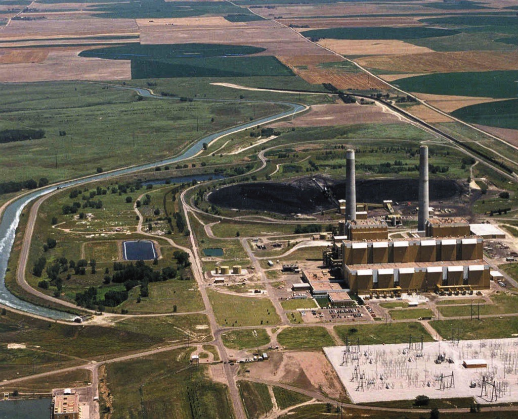
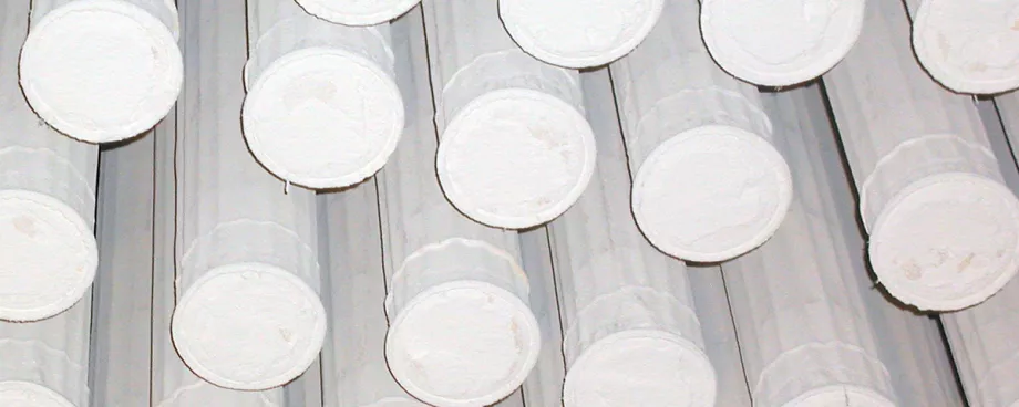
Filter bags are a physical barrier and therefore the cleaning efficiency does not show pronounced dependency on gas and dust properties like in electrostatic precipitators (ESPs). Lower emissions can be maintained in a more economical way and no CO shut downs are necessary. On the other hand filter bags are more susceptible regarding upset conditions (in particular temperature peaks, condensation and abrasion), therefore process control has to focus on other parameters than for ESPs. The bags are responsible for troubles with bag filter in just some cases but are typically the component which is finally failing.Lab analyses of failing bags are a way to determine the mechanisms (mechanical/chemical) responsible for the damage. Initial failures are often resulting in secondary problems - it is also important to know about the distribution of failing bags within the bag house. For a detailed determination of the cause for damage, and subsequent decision on corrective measures, information on condition of e.g. cages, cleaning facilities and sealing is essential.Some typical failure patterns will be presented (operating problems, lab analysis and plant performance after corrective measures) and successful solutions to solve bag related problems discussed.
Cost Overview - Bag House Operation and Maintenance
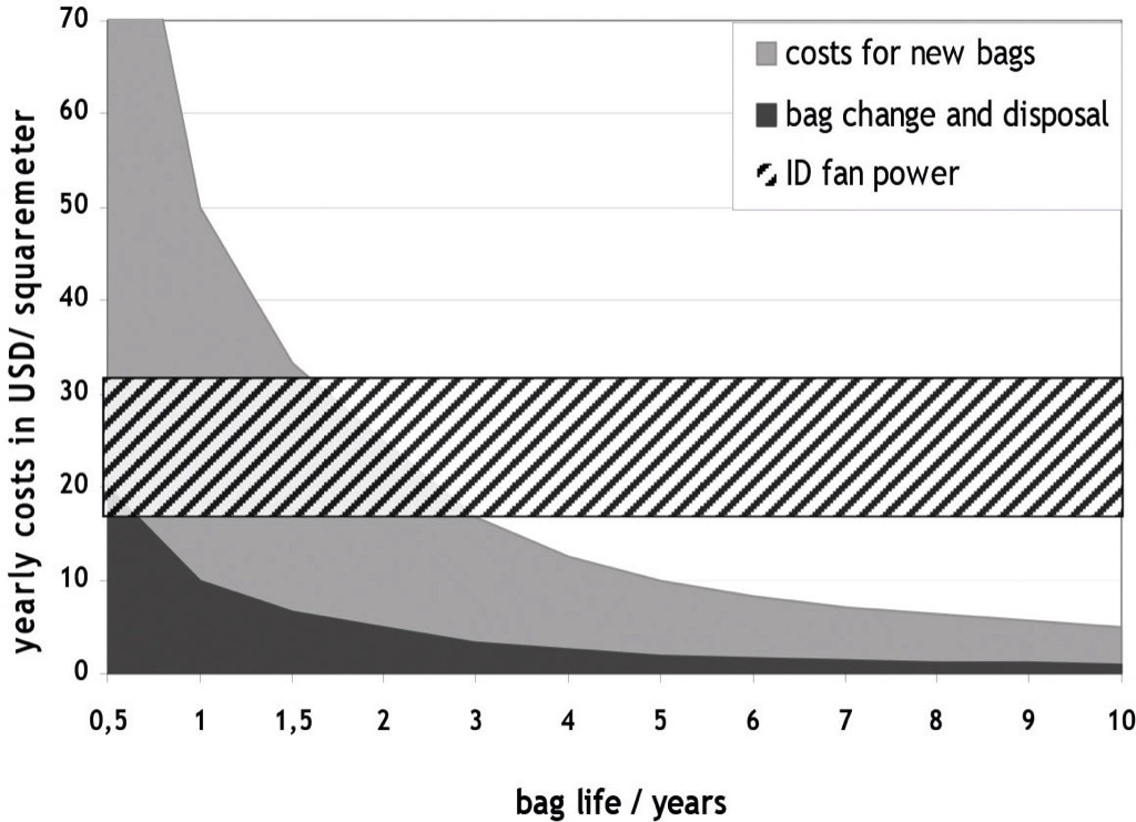
The operation of a bag house results in expenses for fan power, pressurised air and bag material as well as cost for manpower and the loss of production during maintenance.Bag costs are typically the most obvious and therefore best evaluated cost factor as it is a big investment at the start-up and at the time of complete replacement.In fact it is typically just number 2 after the fan power. With its effect on all other operating costs the choice of bags has to be made properly, including the evaluation of its effect on other costs.In Fig. 2 the operating costs for a bag house are displayed, split in cost for new bags, bag change and disposal and ID fan power. Major differences and therefore a wide range of each single cost factor has to be considered for different applications and bag house layout.
Experienced Operating Problems - Causes
The operator experiences 2 different types of typical problems:
- increased pressure drop of the filter unit
- increased dust emissions
Premature bag failures and therefore high emissions are often experienced after problems with high pressure drop. In general it is often a concatenation of problems which do not always originate from the bags but bag failures are what is finally experienced.
The Pressure Drop in the Filter
The pressure drop across a bag house consits of the pressure drop of the housing (valves, ductwork,..) the pressure drop of the filter sleeves and the pressure drop of the dust cake upon the sleeves. An increased pressure drop is not always indication for problems, but are due to fundamental physical laws.
The Pressure Drop of the Dust Cake
Influences on the pressure drop of the dust cake are
- Air to cloth ratio: The air flow in the dust cake and in the filter sleeve are both laminar and therefore the pres-sure drop can be considered to develop app. linear with the filter face velocity (air to cloth ratio) if cleaning is time controlled.
- Dust load: With time controlled cleaning the pressure drop of the dust cake increases app. linearly with the dust load. The development may be slightly progressive as the dust cake may be more compact when exposed to higher pressure drop.
- Dust properties: Finer dust results in a denser dust cake with finer pores and higher specific pressure drop.
Some dust components may result in a dense blocking layer. One example is ammonium sulphate. The particular problem is that salts decompose at temperatures around 300°C and crystallisation takes place on the filter media. This results in much stronger bonding between dust and filter material than from inert dust. Membranes appear to have a more pronounced susceptibility in this regards, leading to immediate and permanent problems with increased pressure drop.Operating conditionsExcessive humidity, (if condensation takes place) can cause sticky behaviour of dust. Condensation in capillary, like between particulate, takes place above the dew point, hygroscopic dust properties further increase the critical temperature. Below a certain humidity the pressure drop will also increase (just slightly, typically without reasonable problems) as binding forces between particles are reduced without contribution of monomolecular water layers on the surface.
The Pressure Drop of the Filter Bags
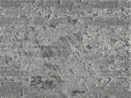
Influences on the pressure drop of the filter fabric are:Air to cloth ratio: Similar as the effect on the dust layer an appr. linear dependency of the pressure drop of the felt from the a/c-ratio can be considered.Above critical limits the stable behaviour (a more or less constant pressure drop over the bag life) ceases and penetration of dust into the felt results in clogging (penetration of dust into the felt or densification of dust close to the surface of the felt).
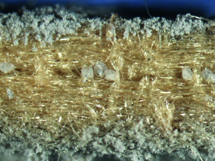
Dust properties and operating conditions: Changing dust properties, which may also be related to changing operating conditions (e.g. humidity, grinding aids, SOx/HCl ratio, phospates,...), influence the amount of dust which remains on the felt after cleaning. Surface coatings can improve dust release and prevent from damage due to sticky dust to a certain degree.Filtration efficiency of the felt: High dust loads and fine dust is often above the limits for standard filter media. Fine fibres and fibres with non-round shaped cross sections are a common approach to increase the filtration efficiency.Typical pressure drop of standard filter media:
- membrane materials 1-2 mbar
- needle felts in stable operation <1 mbar
- membranes in operation (after cleaning) in best case close to values of new membranes
Depending on the construction of the filter media and dust properties different typical failure patterns can be observed which result in either an increased pressure drop, increased emissions or both. This topic is discussed later on (penetration of dust through the bag material without appearance of macroscopic holes).
Reasons for high Emissions
Well performing needle felts and membrane materials offer emissions not exceeding single digits of mg/m³. Higher emissions are indication for penetration due to
- leakages of the filter (welding/corrosion) improper sealing between bags and cell plate
- faulty seams of the bags
- holes in the bags
- penetration through the bag material without macroscopic holes
Leakages/improper Sealing
Leakage tests with fluorescent powder are useful for identification of macroscopic holes. Seams are a critical point if not properly made, welded seams as well as stitched seams. Experienced manufacturer ensure adequate processing into bags.
Holes and Cracks of Bags
The listing below presents different causes for holes and cracks which are explained and illustrated afterwards:
- Chemical aging: loss of tensile strength- thermo-oxidative ageing- hydrolysis/condensing acids
- Shrinkage/elongation (excessive temperature)
- Mechanical wear- abrasion from locally high can velocities- abrasion from pulsing (improper adjusted cleaning nozzles, rust or dust from the clean gas plenum entering during cleaning)- mechanical wear along folds (oversized bags)- abrasion along cage wires (corroded/damaged cages, improper cage alignment ––> bag-bag or bag-wall contact)- burden from incorporated dust (penetration)
Laboratory analyses of bags can help to identify specific damage patterns if bags are failing, chemical damage can be detected to differentiate between rather mechanical or chemical causes.Chemical aging: A loss of tenacity below critical limits results in cracks and holes. These often appear similar as holes from abrasion but chemical ageing is the reason for an increased susceptibility for mechanical damage (e.g. often observed when polyester is damaged from high humidity in clinker mill filter – high dust loads resSEM-picture of a dense pult in abrasion of the weakened material). Material specific analytical methods can identify and quantify chemical damage to deviate between rather mechanical or chemical causes.Considering suitability of the material for particular operating conditions condensation is a frequent problem which is often locally pronounced in the filter. Reasons for local condensation are cooling of the gas below the dew point due to improper thermal insulation of the filter (failures accumulate along walls), air leakages (typically effecting bags adjacent to doors) and the cooling effect during pulsing (typically resulting in damage in the top section of the bags)
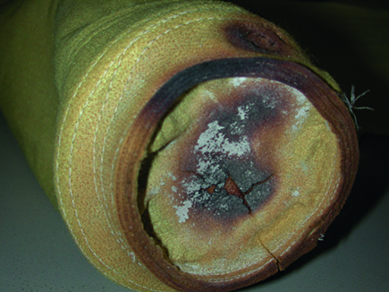
Shrinkage or elongation - excessive temperature: Short time temperature peaks do not cause a high degree of chemical damage to fibre material but rather influence its dimensional stability. Depending on fibre material and load during operation shrinkage or elongation is typically experienced.A locally pronounced failure can be observed if high hopper levels result in locally high temperatures at the bag bottoms. Elongation due to peak temperatures above the material limit can result in folds and mechanical wear as shown later on.
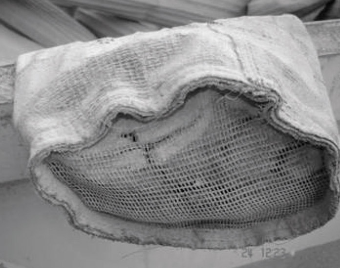
(Excessive) mechanical wear: This may be due to abrasion from locally high can velocities. Locally high gas velocity and re-entrainment of dust from the hopper is resulting in abrasion of the bag material. Even some bag materials show lower susceptibility against abrasion adaptions of the flow distribution are the only way for stable operation of the filter in this case.Abrasion from pulsing is often observed as secondary failure pattern when dust from the clean gas plenum is blown into the bags during pulsing. Abrasion starting from inside close to the bag top end is indication.
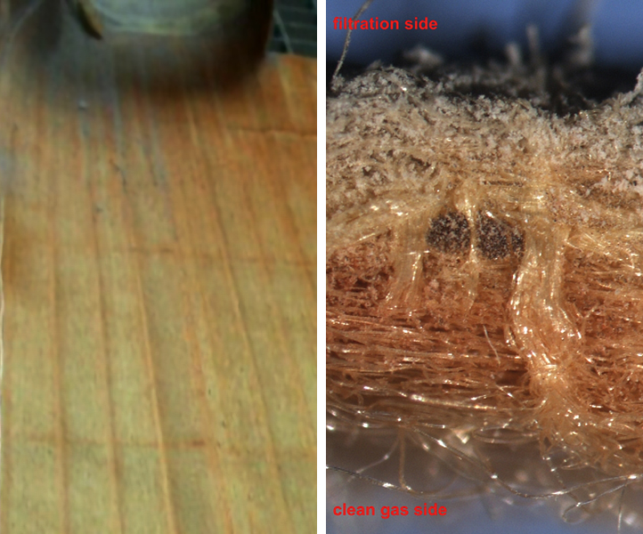
Pronounced asymmetric appearance may indicate wrong adjusted cleaning valves/venturis.Red-brownish discolouration of the bag top section from rust is an indication for corrosion (e.g. as a result of condensation) as cause for abrasion from rust. Condensation may be the result of a cool-down below the (acid) dew point during pulsing, leakage due to improper sealing or insufficient insulation (Fig. 7)Abrasion along cage wires: Damage along cage wires is typically experienced when the cages are damaged or corroded, or after bag-to-bag or bag-to-wall contact due to misalignment of cages (Fig. 8).Mechanical wear along folds: Holes may also result from increased mechanical burden close to a longitudinal fold (e.g. oversized bag). Elongation in cross direction during operation has also to be considered for a misfit of bags on cages. (Fig. 9)
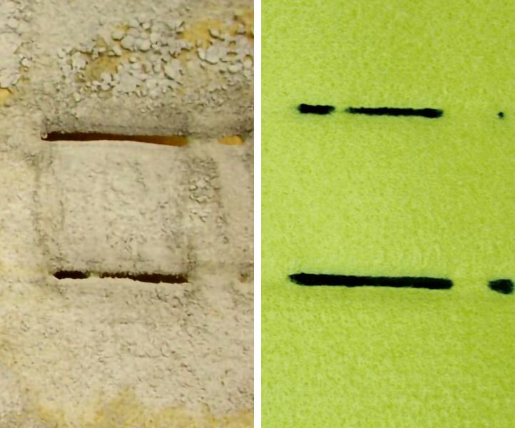 Fig. 8: Hole along cage wire uncleaned (left) and cleaned (right).
|
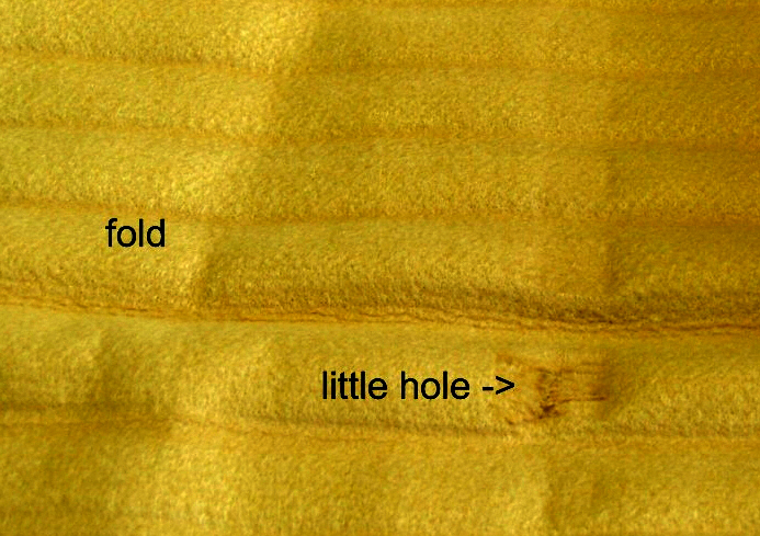 Fig. 9: Hole as a result of increased mechanical load due to oversizing.
|
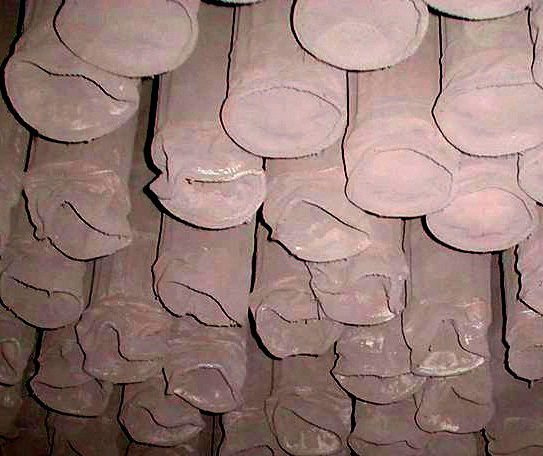
Elongation in length direction results in folds at the bottom end and increased burden close to bag bottoms.
Membranes and Needle Felts - A Comparison
Membranes are a thin, almost 2-dimensional layer. The bag life of membrane bags are in many cases limited by increasing damage of the membrane which is leading to increased emissions and/or increased pressure drop (depending on operating conditions and construction of the supporting felt or fabric). Penetration of dust into the supporting material is also leading to increased mechanical burden (internal abrasion) which results in cracks.Needle felts are a 3-dimensional structure and damage of the surface layer (e.g. from abrasion or during mounting) does not result in failures as the next fibre layer is acting as new surface layer.
Typical Failure Pictures (Fig. 11)
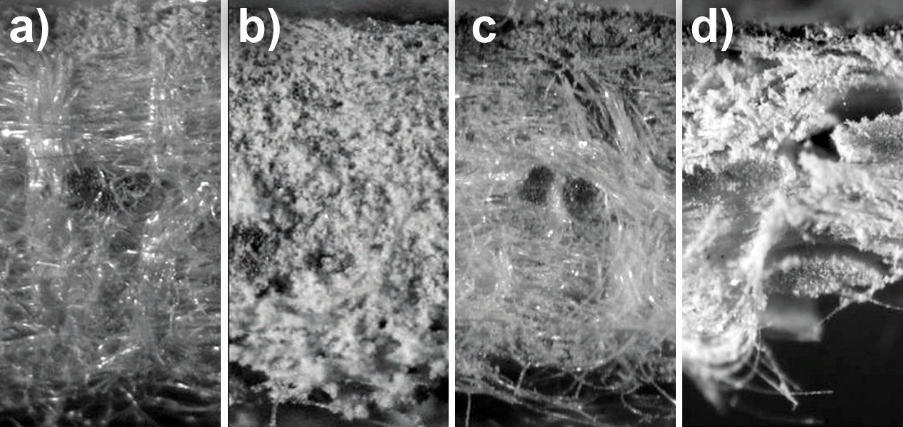
Needle felt: Penetration of dust into the felt is typically resulting in increased pressure drop. Totally penetrated felts like displayed in the right picture show increased emissions. Needle felts which are constructed to meet the demands of a particular application can ensure high filtration efficiency on a long term. The bag life is typically limited by mechanical and chemical ageing of the fibre materialMembrane on needle felt: After membrane damage dust accumulates behind the membrane, resulting in increased pressure drop. Increased cleaning pressure to release the membrane is a way to overcome acute problems with blocking, the needle felt has to overtake filtration afterwards.Membrane on glass fabric: The open scrim does not favour clogging after membrane damage but rather penetration as it does not offer sufficient filtration efficiency for pulse jet applications.
Increasing the Filtration Efficiency
One of the main challenges in todays filter constrution is to improve the efficiency of the filter materials. Ways There are differnt solutions to fulfill this task and to prevent dust from penetration into the felt.The implementation of fine fibres increases the fibre surface and decrease pore size. Blends of different fibre titres on the one hand make it possible to use finer fibres than processible on their own (during felt production) and on the other hand result in derived, narrow pore size distribution.The use of structured fibre cross section: trilobal and multilobale fibres increase the fibre surface (when the felt weight is kept constant). Fig. 12 displays the specific surface of different fibre materials depending on the fibre titer. In addition low velocity areas exist between the lobes of the fibres where dust can be accumulated without an increase of the differential pressure drop.
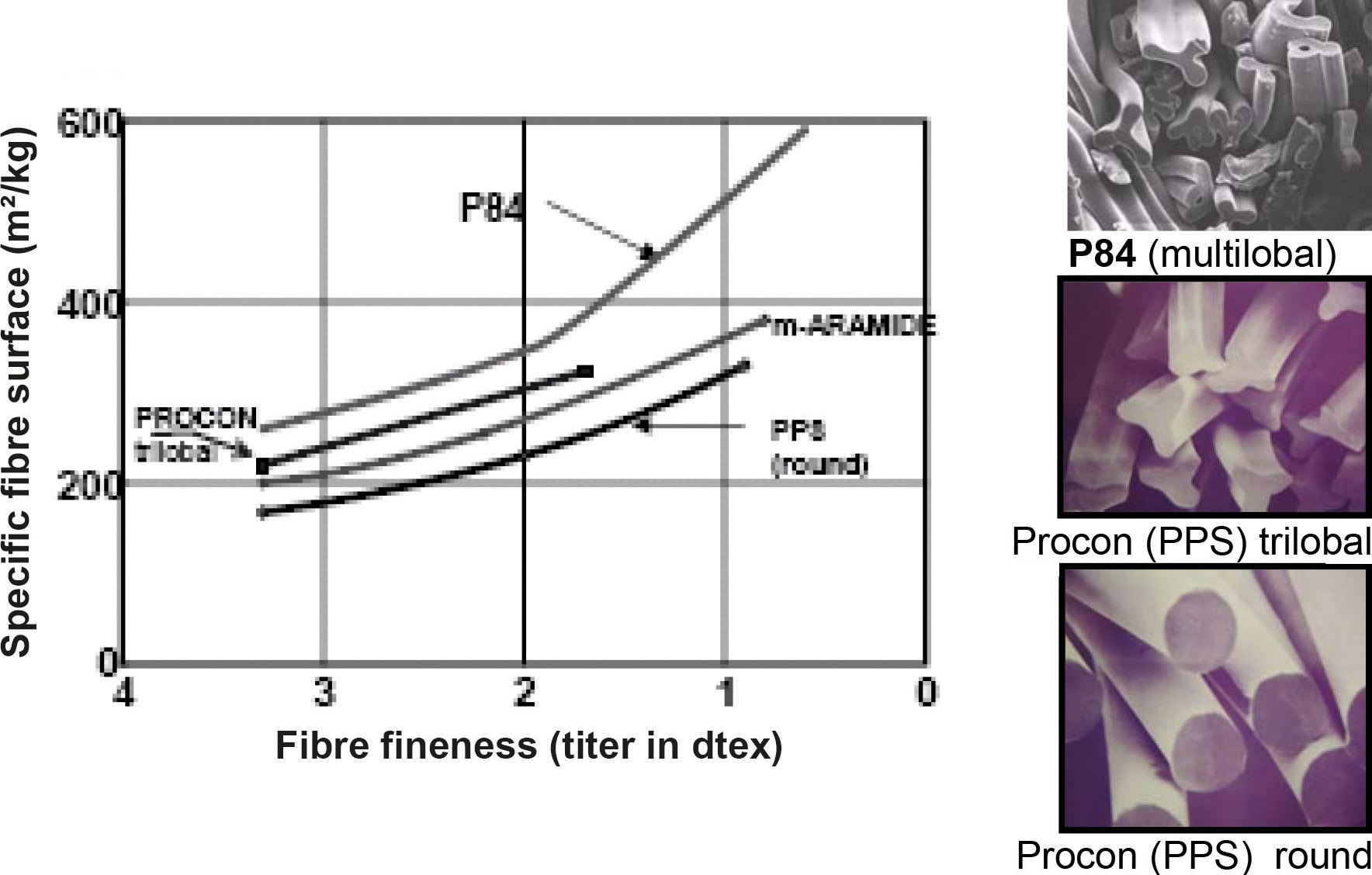
Higher felt weight and denser needling can improve the pressure drop along the bag life due to decreased penetration of particulate into the felt. By a weight increase additional stability can be obtained for chemical or mechanical challenging applications.‘Blending’ has a rather negative image as often cheaper materials have been used for blending just to offer felts for a lower price than competition. The list of examples is long: e.g. glass blended in PPS (poly phenylen sulfide) or m-aramide, yellow polyester or polyamide-imide in P84 (polyimide) felts. This kind of blending usually results in reduced felt quality concerning chemical stability and/or filtration efficiency. Premature failures as a result of fibre degradation or blinding and dust penetration are experienced.When chosen properly the blend can combine superior filtration behaviour and chemical resistance and be better than the 100% felts of each of the blending partners.With fibre blends it has to be noted that chemical and thermal stability are mainly determined by the major blending partner. Addition of smaller amounts of fibres with higher stability does not significantly improve the thermal and chemical stability of the blend. On the contrary an improvement of the filtration efficiency is possible by adding smaller amounts of fine fibres or fibres with non-round shaped cross section. P84 (polyimide) offers the highest specific surface amongst commercially available fibre materials for filtration and is a preferred blending partner to increase the filtration efficiency for base materials ranging from polyester to PTFE.
Summary
Bag house operating problems are related to the bag material in just some cases but bag failures are commonly observed finally.To determine the cause needs a detailed analysis not just of the bags but also of construction and condition of the entire bag house and operating conditions. Support is offered e.g. from bag house OEMs, bag/filter media supplier and fibre supplier. A detailed analysis of all relevant parameter is the solution for satisfying performance of filter units.The cost of filter bags should not be taken as only base to choose a material without evaluating the influence of different materials on pressure drop and bag life. Higher value materials often pay back if better performance and higher process stability can be achieved.
References:
- Rathwallner, G.: Troubleshooting frequent Baghause Operating Problems; World Cement November 2009;
- Rathwallner, G.: Typical problems during operation of a bag house; Powder & Bulk Solids India, Mumbai, 2013.
| About the Author | |
| Dr. Georg RathwallnerEvonik Fibre GmbH, Austria |
■


