
(From the archive of ”bulk solids handling", article published in Vol. 35 (2015) No. 4 , ©2015 bulk-online.com)
Pipe conveyors were initially designed by a Japanese conveyor company in the late 1970’s as an innovative solution to enclosed conveyor system solutions. In 1990 the bulk material industry received approval to freely use this technology. This allowed for large leaps in technology, making pipe conveyors a more effective way of conveying bulk material. However this did not last as pipe conveyors are perceived to be more expensive and difficult to maintain. In the following sections it will be shown that pipe conveyor solutions are not only viable but more effective then troughed belts in many respects.
Description of Mechanisms
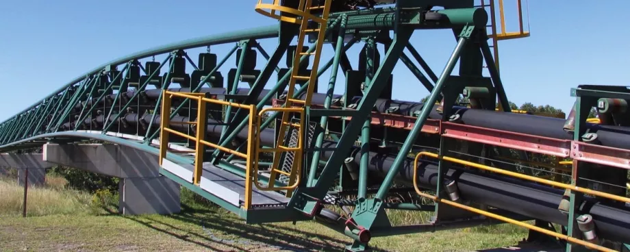
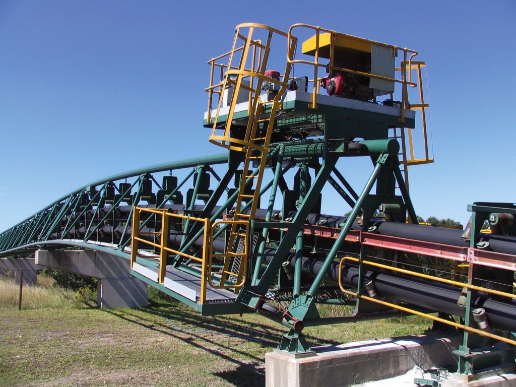
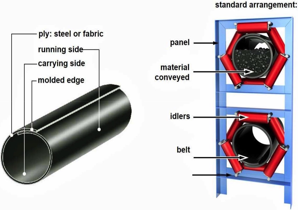
Pipe conveyors are simply troughed conveyors which form an enclosed pipe. This is achieved by increasing transition idler angles and eventually six roll idler configurations on a specified diameter. The transition distance at the tail and head end of the conveyor is responsible for gradually shaping the belt. This change in shape from trough to pipe has had far reaching effects on the design and equipment used in bulk material conveyance.
Pipe Conveyors: Advantages
Pipe conveyors provide effective solutions for a variety of problems faced in the industry, this includes
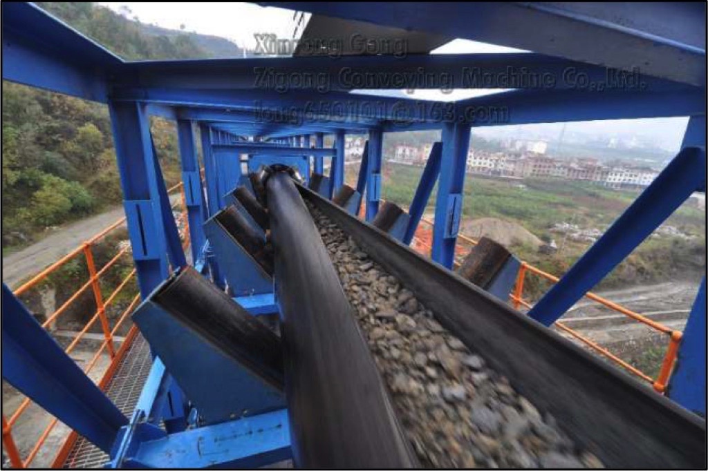
- Spillage free transportation of material is obtained due to the enclosed belt.
- Material build-up on idlers is reduced, decreasing maintenance, as no material is spilled during transit.
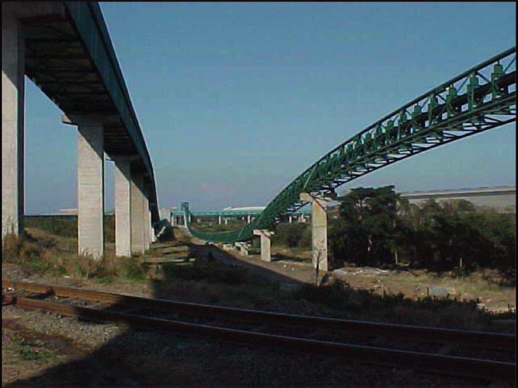
- Pipe conveyors fit into narrow areas and save space in congested areas. This is possible due to a circular belt profile, allowing the gantry width to be reduced.
- Can negotiate tight horizontal and vertical curves because the material is enclosed within the pipe and cross belt slip is reduced by the idler configuration.
- Greater rate of elevation is obtained due to the increased contact between belt and material.
- Has better belt edge damage control, due to improved belt training.
- Weather resistance to wind and rain is improved as the material is enclosed, therefore gantry does not require covers.
- Ecologically/environmentally friendly as it is able to pass around sensitive areas and negotiate remote terrain.
Disadvantages
The formation of the pipe conveyor does not come without its disadvantages; however these often become negligible in light of the large improvements to that the pipe provides.
- Pipe conveyors have larger power requirements due to the large additional amount of idlers
- Larger belt widths are required to form a pipe diameter capable of conveying the same material as a troughed conveyor (considering both belts run at the same speed)
- Overloading and over-sized particles are more likely to cause problems in the system. This is because of the limited space available within the closed pipe compared to open troughs of standard systems.
- Due to the completely enclosed arrangement of the belt and idlers maintenance and removal of the belt is more difficult.
Comparison between Pipe and Troughed Conveyors
Carry Capacity
Table 1 shows the carrying capacity of pipe and conventional conveyors. This example allows for 70% fill factor and a belt speed of 4 m/s for a material density of 1000 kg/m3.From this we find that the belt width of pipe conveyors is far larger than that of conventional conveyors for the same tonnage. This must be carefully considered when choosing between pipe and troughed conveyors because of the cost of belting.
| Belt width[mm] | Pipe diameter[mm] | Capacity pipeconveyor [t] | Capacity beltconveyor [t] |
| 1000 | 250 | 500 | 1300 |
| 1200 | 300 | 720 | 1900 |
| 1400 | 350 | 1000 | 2600 |
| 1600 | 400 | 1300 | 3500 |
| 1800 | 450 | 1600 | 4450 |
| 2000 | 500 | 2000 | 5500 |
| 2400 | 600 | 2850 | 8400 |
Route Layout
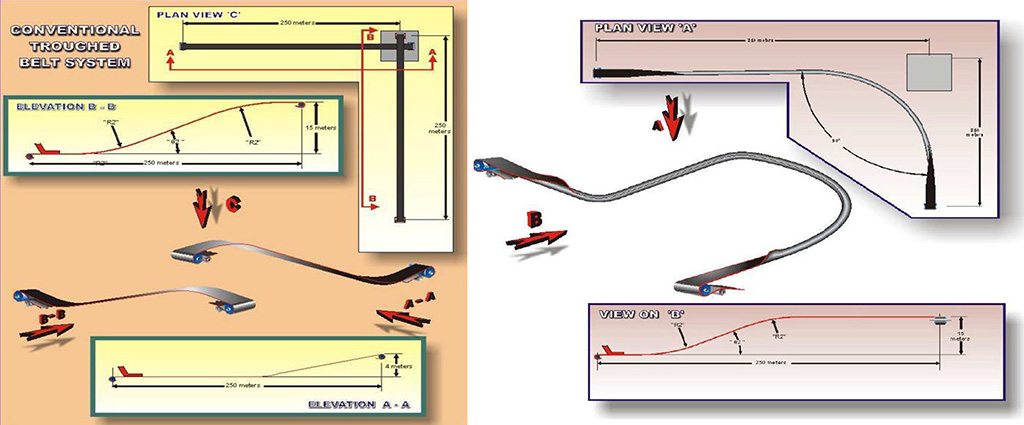
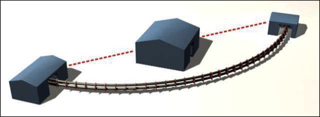
From the analysis in Fig. 4 we find that the pipe conveyor allows for fewer transfer points because it is capable of negotiating tighter curves and inclines. The increase in horizontal and vertical curves further increases the power requirement. Conventional conveyors will require large inclines to feed into the following transfer increasing the power requirements. From this we see that depending on the route, length and curves either pipe or conventional conveyors will be used.
Power Requirements
The basic power comparison (Table 2) was carried out for a conveyor running 2000 t/h at 4 m/s. The route includes multiple horizontal curves with 5000 m radius.
| Pipe conveyor 2000 mm wide | 1600 kW |
| Belt conveyor 1200 mm wide | 1200 kW |
We expect the power consumption of the pipe conveyor to be higher due to added idler friction and large belt mass. This does not make the troughed conveyor a better solution; it simply shows the difference in supplied power.
Structural Components
Above we noticed that to carry a similar amount of material on a pipe required a wider belt than that of conventional conveyors (Table 3). Below we see that the required belt grade/rating for pipe conveyors are lower than that of the conventional conveyor (Table 4). The tension within the belt in order to pull the belt is distributed across the belt, for this reason the rating of the belt is lower for pipe conveyors because a wider belt it used.
| Pipe conveyor | 45 kg |
| Belt conveyor | 30 kg |
| Pipe conveyor 2000 mm wide | ST 1200 |
| Belt conveyor 1200 mm wide | ST 2000 |
Idler spacing is to be kept lower for pipe conveyors in order to maintain the shape of the pipe. This drastically increases the number of idlers and brackets (Table 5), which in turn has significant effects on the cost of the conveyor.
| Pipe conveyor | 2 m spacing | 5000 |
| Belt conveyor | 3 m carry spacing | 1664 |
| 6 m return spacing | 832 |
Pipe Conveyor Theory
Pipe Conveyor Calculations
Belt Tension
Belt tension calculation for pipe conveyors is carried out in the same fashion as troughed conveyors. Two major properties of the belt to consider is what provides the tensile strength of the belt (reinforcement of a carcase) and the belt resistance to surface damage (i.e. elastomeric cover grade). Belt selection considerations include:
- The belt strength must be sufficient to transmit the power across the span of the conveyor.
- The belt carcase must be able to support the material duty, conform to the idler configuration when empty (troughability) and allow for enough flexibility to wrap around pulleys.
- The quality of the belt cover must be suitable to withstand the physical and chemical effects of the material being conveyed. This includes abrasion, temperature of material and corrosive effects.
In order to calculate the power requirements and choose a suitable belt for the conveyor; calculation of the belt tension is required. Factors to be considered are
- Friction factors of the system such as belting material and pulley construction.
- Material and belt mass per unit length.
- Conveyor profile with regards to horizontal and vertical curves.
- Conveyor configuration with regards to idler spacing and pulley configuration.
Equations are formulated to calculate the effects of each of the above considerations:
where:
where:
 |
where:
Power Requirements
The power requirements for pipe conveyors are calculated in the same manner as troughed conveyors. We find that for a straight inclined conveyor the power requirements for the troughed belt are lower than that of the pipe. The additional power is as a result of forming the belt and increased friction between the belt and idler sets. When considering curved profiles, power consumption increase as a result of changing the horizontal direction of material within the pipe.Power requirements increase with the number of transfer points; this is due to the increased power to raise the conveyor to the required height for transfer to the next conveyor. Pipe conveyors require fewer transfers as they are capable of negotiating tighter curves (smaller radius). For this reason pipe conveyors gain an advantage of lower power consumption when conventional troughed conveyors would require many transfer points.
where:s = belt speed
Conveyor Profile
Due to the enclosed pipe profile and 6 idler support configurations, pipe conveyors are capable of negotiating tighter curves, with a smaller radius. When tilting the frame on horizontal curves, material is safe within the pipe reducing spillage at these points. This also has its shortfall in that the greater change in direction causes a larger tension in the belt and power requirement of the drive.
A comparison of troughed and pipe conveyor routes is shown in the corresponding section above.
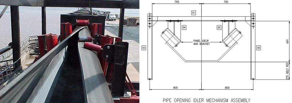
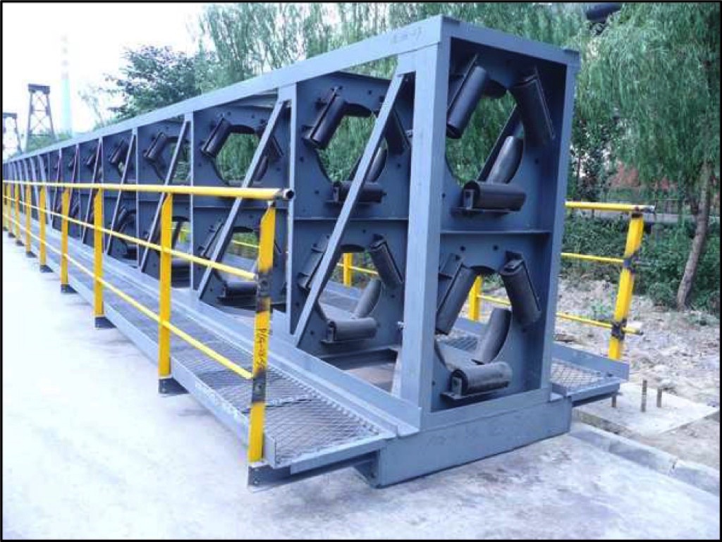
Idler Design and Mounting
The idler configuration maintains the shape of the belt and provides support for the belting over the profile. The bottom three idlers support the load and the top three to keep the pipe form. For this reason, idler configuration for pipe conveyors has been the subject of many discussions over the years. Major concerns are:
- Large friction between the belt and idlers increases power demand and wear.
- Belt training to reduce pipe rotation which allowing leaks in the pipe.
- Idler and support structure alignment to ensure minimal belt wear and friction.
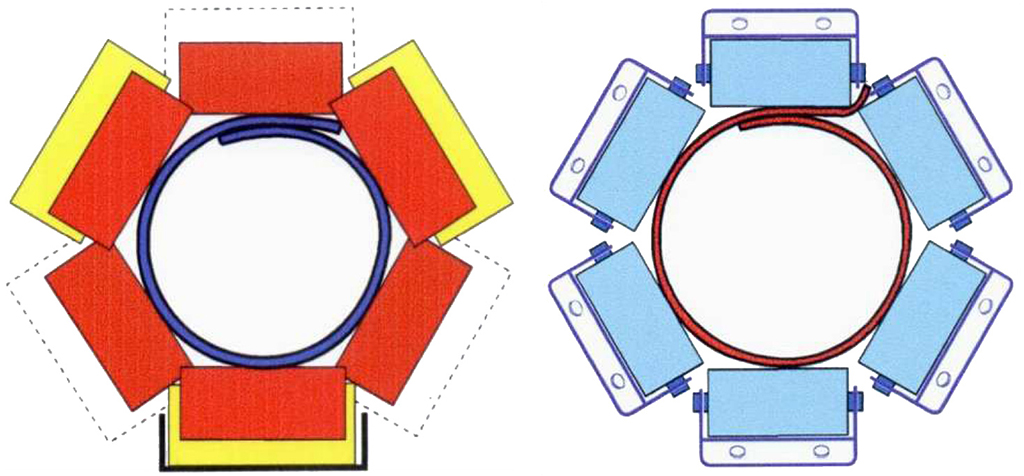
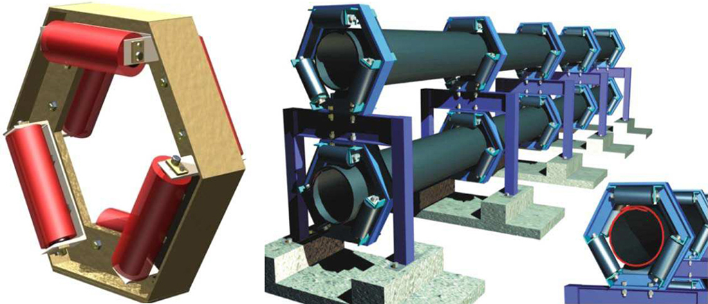
Idler configurations consist of two sets of three idlers in a hexagonal shape. Originally Idlers were all placed on one side of the support panel, this caused idler interference and belt edge wear. To ensure this does not happen, Ckit proposed the new Idler configurations which are discussed in the last section.
Belt Training Procedure
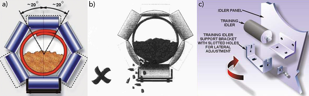
Belt training is important to pipe conveyors in order to prevent belt fouling with the structure, chute work etc. This will result in permanent damage to the structure and belt. Furthermore belt alignment is used to keep the overlap in the belt at the vertical top of the pipe form. This is done to reduce spillage, as seen in Fig. 10.
Belt training is to be carried out for three conditions, no-load, partial-load and full-load. Training of the belt is done by one person to reduce redundancies and duplication.The testing procedure is as follows
- Station personnel along the length of the conveyor to monitor the pipe rotation.
- Station personnel at the head and tail end to monitor the pipe forming
- The belt overlap is monitored with reference to the structure , making sure it does not rotate more than 20° clockwise or anti-clockwise
- If the belt rotation is greater than 20° belt training is required.
The procedure for belt training is as follows:
- Training of the belt is carried out by one person to reduce redundancies and duplication of idler adjustments.
- Training the belt requires the responsible person to rotate and position the bottom idler of the configuration.
- Training of the belt begins at the tail end of the conveyor.
- First adjustment is to the tail pulley, then loading and transition section, and along the carry side to the head end pulley.
- Once at the head-end section, training follows the belt through the take-up, drive and head pulley.
- Training is complete once the return belt has been adjusted.
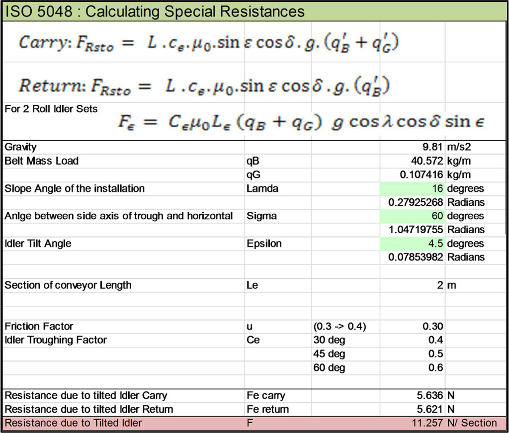
Effects of Idler Support Structure Alignment
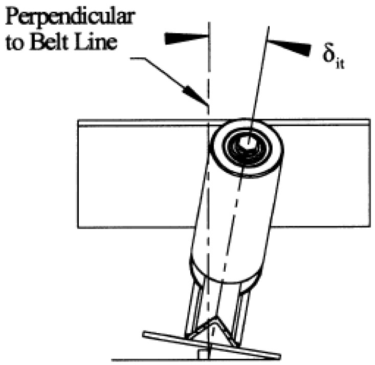
Idler support structures have a large impact on the running of pipe conveyors and can be the difference between success and failure of a project. Correct mounting of the idlers result in lower power consumption and less wear on equipment. From experiences in India of poor erection of idler support structures we find that further resistance is added through tilt resistance (Tt). This model is currently being analysed by our team in order to minimize its effects. The model is based on the prerequisites presented in Figs. 11 and 12.
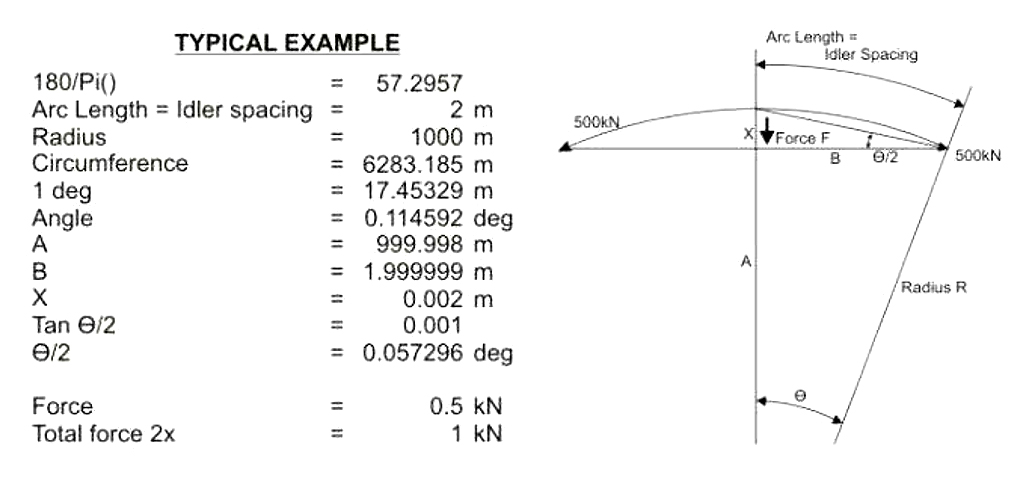
As material flows through horizontal curves, we find that the change in direction of the material increases the required power. This is based on the analysis according to Fig. 13.
Ckit Contributions to Pipe Conveyors
Idler Mounting
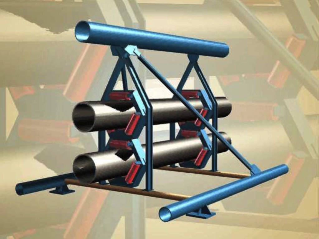
Ckit has developed idler brackets mounting whereby one set of three idlers is on the front of the bracket and one set of three is at the back of the bracket. This reduces belt pinching between idlers which cause belt edge damage. This also reduces the interference between idlers, which often occurs when mounted on a single side.The mounting of the idlers has also been modified to decrease its mass while maintaining rigidity; this reduces the load bearing pressure on the trestles. This reduction has a major effect on the trestle and footprint design. The smaller frames allow it to be easily mounted within the triangular gantry area (Fig. 14).
Triangular Gantry
To reduce the mass of the gantry, the cross-section was changed to a triangle, this allowed for less steelwork with the same rigidity (Fig. 15).
Maintenance Trolley
Ckit designed and developed self-propelled maintenance trolley has been a revolutionary design for conveyor technology. It allows for maintenance personnel to easily perform inspections and maintenance on damaged idlers and related structures (Fig. 16).
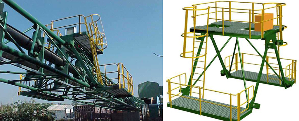
The trolley is large enough to carry all equipment and spares, making maintenance quicker and therefore reducing downtime. The trolley is driven via hydraulic motors and is supplied with a power generator to carry out maintenance where required.
| APPENDIX: Frequently Asked Questions | |||
| 1. | Q: Can a pipe conveyor convey material vertically? | A: No, the pipe conveyor can be inclined at up to 20% greater grades than a trough belt conveyor; however, vertically conveying is not possible. | |
| 2. | Q: What is the maximum length of a pipe conveyor? | A: The longest pipe conveyor installed is approximately 5,2 km in length and conveys petroleum coke at approximately 300 tph in a 12 in (300 mm) diameter pipe. Krupp Robins, Inc. in the USA supplied this conveyor. Conveyor Kit’s longest pipe conveyor is a 450 mm diameter pipe with a conveying capacity of 1800 tph. The transport distance is 3,2 km. This conveyor is at Indo Gulf inIndia. Current technology is making pipe conveyors of up to 10 km in length feasible. | |
| 3. | Q: Can a pipe conveyor negotiate a 90° bend? | A: Yes. Currentlytechnology enables us to engineer pipe conveyors to deflect through a horizontal angle of 90°. An example of this is the Indo Gulf pipe conveyor designed by Conveyor Kit. The layout of each specific installation must be checked to ensure that a sharp bend can be accommodated. | |
| 4. | Q: What is the maximum lump size, which can be handled in a pipe conveyor? | A: The rule-of-thumb is that the pipe diameter should be four times the maximum lump size. Depending on the percentage of larger lumps however, this can be reduced to three times maximum lump size. The largest diameter pipe conveyor supplied by Conveyor Kit has been 450 mm. Pipe diameters of 500 mm and larger are theoretically feasible. | |
| 5. | Q: What is the belt speed of a pipe conveyor? | A: The belt speed, pipe diameter, capacity, site conditions, material characteristics and lump size are selected for each specific installation. The greatest belt speed on a Conveyor Lit pipe is 4,2 m/s on a 900 m long, 2500 tph installation at Richards Bay, South Africa. Belt speeds of 6 m/s and more are possible but may not be practical. | |
| 6. | Q: What are the advantages of using a pipe conveyor rather than a troughed conveyor? | A: Pipe conveyor technology has come far in the last 50 years or so and presently is on par with trough conveyor technology. As such, these conveyors can be compared. The choice of conveyor for any application should be weighed up against the specific criteria and objectives of each customer and/or site. The pipe conveyor has the following generic advantages:a. The belt encloses the material on the carry-side. This eliminates spillage and protects the environment and product conveyed.b. On the return-side the belt encloses the dirty side and eliminates spillage along the conveyor. This is advantageous environmentally and reduces on-going clean-up costs.c. The pip conveyor can negotiate tight horizontal and vertical curves thereby eliminating transfer points and multiple troughed conveyors to perform the same duty of one pipe conveyor.d. Material can be conveyed along the top and bottom strands simultaneously, along the same route, without spillage or contamination of the product.e. The pipe conveyor is cost-effective. In some instances the pipe conveyor has a lower total capital cost than multiple troughed conveyors with transfer buildings, etc. | |
| 7. | Q: Is the pipe conveyor belt similar to the troughed conveyor belt? | A: The required flexibility in a pipe conveyor belt to form and maintain the tubular shape is partially dependent on the belt design. The pipe conveyor belt is thus different to the troughed conveyor belting. There are a number of suppliers of pipe conveyor belting worldwide and pipe conveyor OEM’s often recommend specific suppliers for spare purposes. | |
| 8. | Q: How many suppliers of pipe conveyors are there worldwide? | A: There are approximately six major suppliers of pipe conveyors worldwide, with substantial reference installation. | |
| 9. | Q: How is the overlap of the carry-side belt prevented from rotating in the structure? | A: The overlap is maintained a the top segment of the structure by:a. Ensuring straight belt splices.b. Ensuring the structure and idlers are correctly aligned.c. Correctly manufactured belt i.e. equal tension across full belt width and the carcass is straight.d. Correct spacing of idlers.e. Employing training idlers.f. Sufficient belt tension.Note: It is usually acceptable for the overlap to rotate approximately 20°to either side of the top-dead-centre. | |
| 10. | Q: What would be the cause of the belt opening up along the closed section? | A: Inadequate belt tension, overfilling, stiff belt (new?), incorrect belt selection or idler spacing too large. | |
| 11. | Q: Why does the return-side belt form a smaller diameter after the first two months, and no longer touches the upper rollers? Is this serious? | A: The overlap of the return-belt is at the bottom of the tubular belt. The weight of the belt itself tends to cause the width of the overlap to increase as one belt edge “wraps” inside the other, thereby reducing the pipe diameter marginally. This phenomenon is “normal” and begins to occur within a month or so of hot commissioning, as the belt’s rigidity reduces with service. This does not usually impede reliability or the operation of the conveyor. | |
| 12. | Q: How frequently should idlers be spaced? | A: The pitch or the carrying and return idlers can vary along a conveyor and may be different for each conveyor. Typical idler pitch can vary from 0,5 m to 2 m. | |
| 13. | Q: Can multiple loading points be used on a pipe conveyor? | A: Yes, provided these loading points are not located on a curve and there is adequate room to open and re-close the belt. | |
| 14. | Q: What criteria are important for idlers? | A: The total rolling resistance is greater for pipe conveyors than for troughed conveyors due to the greater number of idlers employed. Thus it is important that roller do not have too high resistance and breakaway force. Roll diameter varies from typical 80 mm to 150 mm depending on the duty, belt speed and locally available standard roll diameters. Conveyor Kit generally uses 14 mm diameter rollers or greater. | |
| 15. | Q: The edges of our belt are chipped and pieces have been ripped out of the edges. What causes this and how can this be eliminated? | A: Some pipe conveyors employ all six rollers on the same side of each panel. In this case the roll face length is selected to enable the rolls to butt-up against each other. It is possible that your belt edge is being trapped between the two rolls and is rubbing against the panel, damaging the belt.Conveyor Kit generally uses 3 idlers on each side of the panel and in doing so, the roll length overlaps so that it is impossible for the belt to rub on the panel. | |
| About the Authors | |
| Sachin RamjeeManager and Design EngineerCKIT Projects, Rep. South Africa | |
| Phil StaplesManaging DirectorCKIT Conveyor Engineers, Rep. South Africa |
■

