
(From the archive of ”bulk solids handling", article published in Vol. 35 (2015) No. 4 , ©2015 bulk-online.com)Feeders are widely used for metering bulk solids and discharging the contents of hoppers and silos. At the smaller scale power requirements may not be economically significant, but for larger units they become very important, as underassessment can have expensive consequences. It can also be difficult to determine what power is actually necessary, on which to allow a safety factor, so possible gross over-assessments incur excess capital costs and long term inefficiencies.
The topic has commanded considerable interest in recent years [1-7], but the subject is complex and general conclusions and formula have been derived from results and may only by valid in similar circumstances to the experimental conditions. A more accurate method of predicting feeder loads is clearly needed, (3), but there is also considered to be a complementary need for an understanding of the factors that influence the load and of good practice design features that minimise their value. Investigations with equipment that does not exploit the mechanics of the prevailing stress system will not yield optimum results.The first task in an investigation is to define the conditions of interest. In the case of feeder loads the main objective is usually to determine the maximum extraction force that has to be provided. The worst case scenario is that of starting with a full bin after a period of time consolidation, taking into account any local vibrations, input loading during filling and any time-related effects on the product condition. However, practical steps can be taken to mitigate initial start and re-start conditions by both design and operating practice. Also, as running periods normally occupies most of the operating time and may be a small fraction of the starting load, steps should be taken to mitigate starting loads and it may be practical to accept a temporary drive overload on starting, provided this is within industrial tolerance.The main operating conditions of interest that may apply are:
- Initial start with full bin following maximum static storage time.
- Initial start with full bin immediately after filling.
- Re-start with full bin.
- Continuous running with full bin. (In practice, running with lower contents tends to take similar power until nearly empty).
The geometry of the bin and feeder must then be considered. These can have different characteristics as below:
- Mass flow with square or round outlet.
- Mass flow with slot outlet. (Feeder must have progressive extraction).
- Funnel flow with square or round outlet.
- Funnel flow with slot outlet and progressive extraction feeder.
- Funnel flow with slot outlet and local extraction feeder.
The size of outlet that is required to ensure reliable flow from a hopper depends on whether the flow regime generated during discharge is of mass flow or non-mass flow design, so the mode of flow prevailing will affect the size of opening, the shape of the stressed arch that forms over the outlet when flow has occurred and the degree of support given to this arch when flow is not taking place. A slot outlet with Mass flow is recommended, at least mass flow for the outlet section, as this offers predictable flow with a good compromise between holding capacity and small outlet size.The nature of the bulk material handled has an important influence on the power required by a feeder, particularly:
- Wall friction on the hopper contact surface. (Incipient value).
- Wall friction on the hopper contact surface. (Sustained value).
- Bulk density in differing conditions of compaction.
- Internal shear strength. (Incipient value). In specific state of compaction.
- Internal shear strength. (Sustained value). In specific state of compaction.
Note that moisture, chemical, thermal and time effects may bear significantly on these values, in which case historical and ambient conditions may be relevant.It will be seen that combinations of the above factors results in many permutations that makes research on this topic an extensive subject to investigate and be tedious and involve considerable overlapping to devise a formula to suit each case. A correctly designed hopper will have outlet dimensions that exceeds the ‘critical arching size’ for the product in the given bin geometry by a comfortable, but not excessive, margin that is sufficient to satisfy the required discharge rate and accommodate foreseeable adverse operating conditions. A hopper outlet of ‘critical arch’ dimensions would offer no additional load on the feeder from material above the arch, but flow reliability would be very suspect unless the ‘worst’ operating circumstances on which a design allowance was made was very unlikely to occur.Clearly, the amount by which the size of opening exceeds the critical arching size has a great influence on the superimposed loads passing through the outlet.A calculated ‘safe’ hopper opening dimension for reliable flow itself is likely to incorporate a degree of safety, but an additional factor is also usually applied as a form of insurance and to accommodate and uncertainty. The resulting dimension must relate to the minimum size of opening specified, so a taper slot outlet that is incorporated to provide an incremental extraction by a belt feeder in order to generate live flow along the whole length of a slot outlet, will present a further increase in span that allows additional over-pressure to develop. Also, if the condition to be stored has a variable condition due to source, process, age or time consolidation, then the design must be based on the ‘worst’ flow conditions. When then handling the ‘easiest’ flow conditions that would pass through a smaller opening, an even greater over-pressure will be generated. In practice, therefore, a hopper outlet size is likely to be significantly larger than the critical arching span dimension.A key concept is that material in a hopper with outlet larger than the ‘critical arch span’ will collapse and flow out, as the principle stress in the arch exceeds the failure strength of the bulk material. The magnitude of the excess principle stress, times the principle stress ratio of the bulk solid, produces a normal force to the surface of the arch that acts down onto the feeder when flow is not taking place.The force acting on the hopper outlet may be considered to have two components:
- The force acting down from the failing arch, which is partially supported by the hopper walls in the case of a mass flow discharge pattern, or by mobilised shear stress on the adjacent static material in a funnel flow regime.
- The weight of the mass under the stressed arch that is totally unsupported by the hopper walls. i.e. from the material in the space between the stressed arch and the feeder belt.
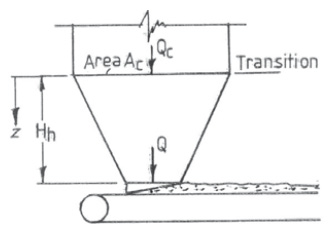
The force acting from the arch is the most important as this determines the ‘drag-out’ load on the feeder. The weight of the mass under the arch is part of the conveying load of the equipment, combined with the continuing load from any extension of the belt from the feeder exit.An important consideration is that, even if flow has not taken place, there is usually some degree of settlement in the lower region of the contents as the bin fills due to the increasing load on the prior contents. The degree to which settlement takes place will be much less for hard, granular material that settle quickly to a stable structure than it is for powders, which tend to land in a dilated condition and consolidate to settle to a higher density as excess air escapes by percolating through the bed. The compacting load on the contents will be limited by Janssen effects, but any settlement will cause a reaction at the bins walls as microscopic slip takes place and develops stressed arches across the bin walls. Through these arches are not sufficiently robust to prevent flow taking place when the feeder allows extraction, they do offer some support for the material above the stressed arches when flow is not occurring.The arches themselves follow a network of continuous load path between contacting particles and roughly adopt a catenary shape, small deviations being possible because contact friction between particles allows slight angular deviations of particle-to-particle contact forces from straight lines of action. Surface tension, cohesive, tensile, electrostatic, molecular and other inter-particle forces may allow other particles to stick on the underside of this arch at the outlet and be subjected to this stress relieving action of the unstable arch, but these effects can normally be neglected for practical purposes.The line of action at the toes of the arch is dictated by the slope of the hopper wall and angle of wall friction in the case of mass flow hoppers, or by the internal angle of friction of the bulk solid for a funnel flow regime. The arch shape can be closely approximated by a parabola, allowing simple calculations to establish the height of the arch and the mass of material between the stressed arch and the feeder that is solely borne by the feeder. Added to this downward value acting on the feeder is the force acting through the stressed arch in either the static or discharge condition. Stresses in the static arch can be calculated by the method used to establish the ‘critical arching size’. It follows that spans exceeding this size are not capable of bearing the compressive stress applied and that, to prevent failure, the arch must be supported by a force equivalent to the value by which the principle stress in the arch exceeds the compressive failure stress, multiplied by the principle stress ratio of the bulk material.Once flow has started the material dilates to a weaker bulk state and lower density. Pressures decrease towards the outlet, by an amount depending on the degree of flow restraint offered by the rate at which the feeder extracts material. However, the shear value also decreases due to the extra freedom of movement allowed by the dilatation, so the ‘drag-out’ resistance offered to the feeder also diminishes.The rub is that the recognised Jenike type method of measuring the initial shear force to ‘drag out’ material from under a hopper outlet is applicable to fine powders, but is not appropriate for coarse, firm granular material, because the confining force does not reflect passive stresses that firmly oppose an expansion of the shear plane in totally confined conditions. For initial shear to take place the mass must dilate locally so that particles that were overlapping in a close-nested, settled structure can move past each other. This dilatation is significantly for large particles. If expansion is resisted by confinement, passive stresses can be exceptionally high, in some cases requiring failure of the particles to allow shear to take place, even though the material in a loose condition may be very free-flowing, as with granular sugar or salt. This condition may be avoided operational by extracting a tiny amount of material at an early stage of initial loading to develop a shear plane in lightly stressed conditions and retaining a small heel of material before re-filling. It also may be avoided by providing a local region of voidage into which the shear plane expansion may move, by way of inserts in the hopper outlet or offsetting the outlet to remove the compacting stresses on the shear plane or providing a local void region.A second practical point is that the development of the shear plane between the gravity flow of the hopper contents and the translationary motion of material on the feeder belt is highly sensitive to the exit geometry from the hopper. For example, Fig. 2 showing a specific arrangement illustrates an increasing taper connection from a ‘V’ shaped hopper, which would usefully generate an expansion of the shear plane, but then restrains the outlet by a profiled cut-out that prevents this shear plane continuing though the end outlet.
It also permits the highest rate of extraction to be taken from the centre of the bin, which optimises the conveying profile on the belt but aggravates flow velocity contours developed in the bin and forces the development of a profiled shear plane below the favourable transition in the hopper construction.
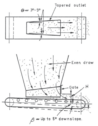
Fig. 3 similarly shows a gate restricting the shear plane to a level below the inclined transition of the hopper walls, although this does allow an even depth of bed to be extracted from the hopper. By contrast, the outlet in Fig. 4 implies extraction by a bed of uniform depth, but the only concession to incremental extraction is the additional material escaping from the hopper side by repose flow.Detail design matters hugely and is not a task for amateurs. Many project engineers consider detail design is the responsibility of draughtsmen, who pay close attention to engineering aspects but are not specialists in powder technology.Subject to the proviso that wall friction has been mobilised, the approach below may be used to assess starting and re-starting forces.
The force required to extract product through a flowing bed is lower than the force needed to initiate discharge because mass dilated by a flowing condition is easier to shear; the higher the rate of flow, the lower the transverse shear strength.It may be difficult to assess the shear strength of a bulk material in dynamic flow condition because of its sensitivity to flow rate, but any feeder capable of initiating flow can sustain discharge continuously.
where:R = Rise at hopper exit to lower inclined edges of hopper wallsW = Width of hopper outlet at startWexit = Width of hopper outlet at exitAverage width of hopper outlet wav
The overpressure from the stressed arch Op
Hence Drag-out force Fdo
where:∫p = principle stress in arch∫f = failure stress of the bulk materialPr = principle stress ratioL = length of hopper outletThe value of (∫p - ∫f) at the hopper outlet is taken for a factor of safety.Considering the conveying load of material under the stressed arch, for practical purposes a catenary arch can be considered as a parabola, which has the general form of
or, in this case, the maximum height of arch, H
The slope at any point
Hence
where:α = angle of hopper wall from verticalφ = angle of wall frictionw = half the width of the hopper outlet, W.Note that the minimum hopper outlet width, W, is generally greater than 1.1 · ‘critical span’ for flow reliability.
Area, A, under a parabolaA = 2/3 · W · Hwhere:H = height of centre of stressed arch.So area A under stressed arch at hopper outlet
Hence weight of unsupported load under stressed arch
where:ξ = bulk densityThe load acting from material in clearance space is
Repose from side skirts
Hence the total conveying load on feeder is
 |
To minimise the feeder load, the width of the exit from the hopper should be based on the critical arching span of the bulk material, with a suitable safety factor and allowance for the increased span incorporated over the hopper outlet length to secure progressive extraction.Reason why outlets are larger than critical span should be critically examined.
- Predictive theories are undoubtedly conservative.
- To accommodate exceptional conditions that may arise rarely, if ever.
- To provide margin to guarantee flow.
- To guarantee the flow rate required.
- To secure progressive extraction from slot outlets.
- Accommodate possible change or uncertainty of product condition.
- Provide extra storage capacity.
- Save storage headroom.
- Poor design confidence.
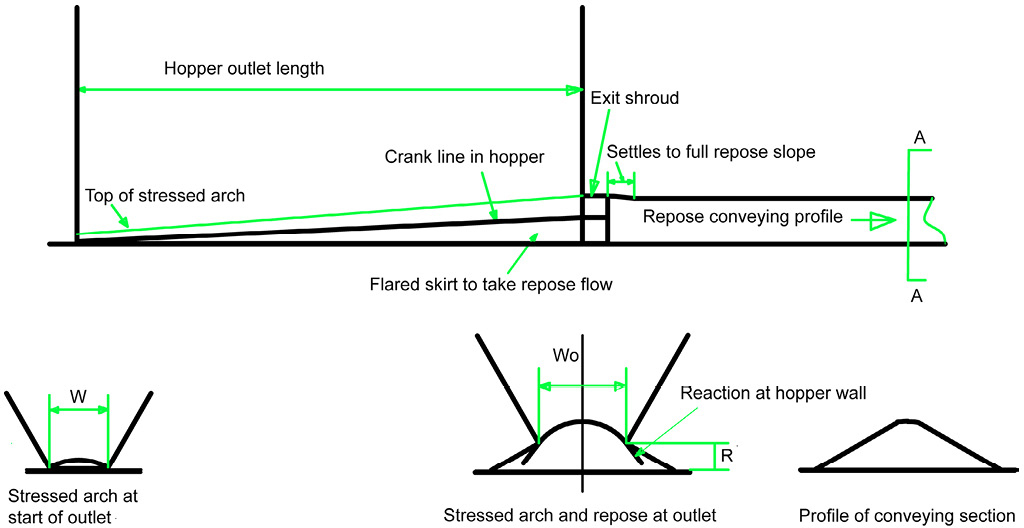
The feeder must accommodate both initial start-up and running loads. The forces required to initiate discharge can be many times that to sustain running, but they only occur for a short time, are usually infrequent and, most importantly. It is therefore good practice to take steps to mitigate these. By contrast, running loads continue through the total operating life of the equipment and determine the essential energy consumption. This paper therefore concentrates on the dynamic condition of operation and means to reduce starting loads. Excess feeder loads increases both capital and operating costs. (Construction, maintenance and power).The shear stress generated by a feeder extracting material from the hopper outlet is dependent on the normal pressure acting, but is also sensitive to whether the failure plane has been previously sheared. This feature greatly emphasises the benefits of initiating discharge under conditions of light normal stress at an early stage of initial filling of the hopper. Very limited belt travel is needed to develop a shear plane. In most cases this can be accomplished before extracted material reaches the end drum of an empty belt.The maximum transfer capacity that can be handled with a flat belt is a triangular cross section with a slope at the angle of repose, θ, of the material, so the width and height of the sides of the exit and the product repose angle determines the belt width required. For a firm, granular product that is likely to be free flowing, the hopper outlet width should be small in relation to the height, to secure the largest slope possible for the shear plane to expand along the hopper length.The hopper outlet width is likely to be dictated by the span necessary to avoid the formation of a structural arch of large granular materials, whereas a wide span needed for a cohesive product may have lower heights because the expansion along the shear plane is less for fine products and a shallower shear plane may be utilised.An interface construction on these lines is shown above with the shape of the exit from the hopper aligning with the stressed arch and repose conditions on the bulk material. There will be a slight collapse of the arch shape at exit as the inclination at the base of the stressed arch will almost certainly be steeper than the repose condition of the bulk.Recommended features to minimise belt feeder loads.
- Ensure that the minimum width of the hopper outlet exceeds the critical arching dimension for the ‘worst’ conditions that must be accommodated, but not by a wide margin. (A vibrator may overcome “Worst’ flow conditions).
- Ensure the hopper outlet length is at least three times its width, to secure the full flow benefits of a slot outlet, but not much longer, to maximise the inclination of the shear plane.
- End the inclined hopper walls with an increasing clearance to the belt along the line of travel to create a stressed arch that can diverge in failure as material moves along the belt.
- Make the exit opening match the stressed arch (in the shape of a parabola, with the ends at the bottom of the hopper ‘V’ walls inclined at (α + φ) to the vertical).
- Allow material to discharge by repose flow from the inclined side clearance to encourage slip on the hopper walls.
- Base the overpressure on the ‘easiest’ flow material and stresses acting on the widest part of the hopper outlet.
- On initial fill, run the feeder for about half the length of the outlet when the level of material covers the outlet to a depth of about three times its width, to develop a shear plane in lightly stressed conditions.
- Leave a ‘heel’ of material in the hopper, to allow re-start under developed stress conditions. (If not practical, consider retractable rods that are inserted in empty conditions and retracted for restart with belt running).
This review highlights the great benefits of generating ‘live flow’ over the total hopper outlet area, paying attention to design detail for the feeder interface, making special design arrangements for initiating the discharge of either hard, granular bulk materials to avoid unacceptable load conditions or cohesive material that would otherwise demand an unacceptably wide span when handling such products.
Brute force is a very poor solution. Project engineers tend to consider detail equipment design to be the responsibility of the draughtsman, who pays attention to engineering aspects, but is not a specialist in powder technology. The interface between hoppers and feeders merits close attention as it is a major factor in capital and running costs.
References:
- Roberts, Alan: Design and application of feeders for the controlled loading of bulk solids onto conveyor belts; University of Newcastle.
- Moore, Brian: Flow properties and design procedures for coal storage bins; Thesis, University of Wollongong 1998.
- Ooi.J.Y., J.M. Rotter: Arching propensity in coal bunkers with non-symmetric geometries; BCURA Project B54. 2005.
- Holmes, Corin, et al.: Start-up and Running Loads Exerted by Bulk Solid Materials on Extractive Belt Feeders: Experimental findings compared with available models; 10th ICBMH. Brisbane. 2009
- Allen, Leo: Belt feeder head load investigation; CEEP Seminar, 2013
- Jie, Guo: Investigation of arching behaviour under surcharge pressure in mass flow bins and stress states at hopper/feeder interface; Thesis, University of Wollongong 2014.
- Ariza-Zafra, Karol: Improving performance of discharge equipment for coals with poor handling characteristics; Thesis, The Wolfson Centre 2015.
- Bates, Lyn: The blockage of a hopper outlet or other flow channel by lumps; Ajax publication.
- McGee, Eddie and Lyn Bates: Design Considerations for Loads on Feeders; Bulk Solids Europe 2012 Berlin, Germany, October 11-12, 2012
| About the Author | |
| Lyn BatesAjax Equipment Ltd., United Kingdom |
■

