
Introduction
In the following the “pressure” acting in a bulk solid is called “stress” in order to distinguish between the stress transmitted through the particle structure and the pressure in the gaseous phase, or liquid phase in case of submerged bulk solids. Stresses in bulk solid containers are usually compressive stresses which are taken as positive stresses. Thus, tensile stresses which are found only rarely, are negative. Both compressive and tensile stresses are normal stresses being represented by the Greek letter σ.
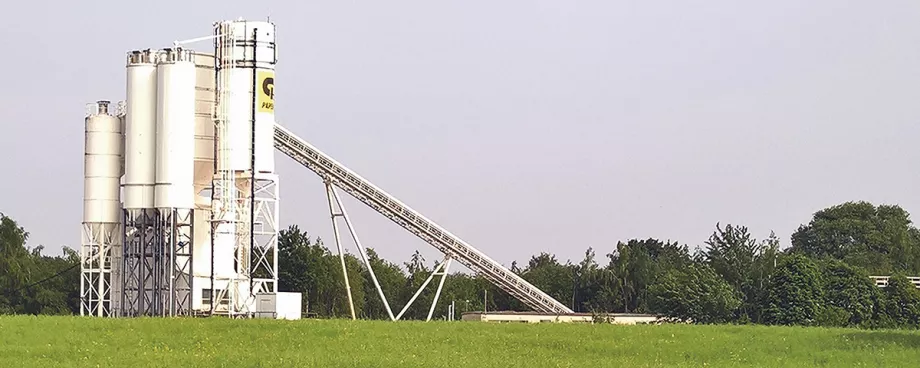
Not only normal stresses, but also shear stresses, represented by the Greek letter τ, act in bulk solids. An example is given by the bulk solid element sliding down along an inclined wall (Fig.1). As a result of the friction at the wall the bulk solid is subjected to a shear stress. On the wall a shear stress of the same magnitude, but opposite direction is acting. The normal stress, σ, acting between bulk solid and wall, is also indicated in Fig. 1.
1. Normal and Shear Stresses acting within the Bulk Solid
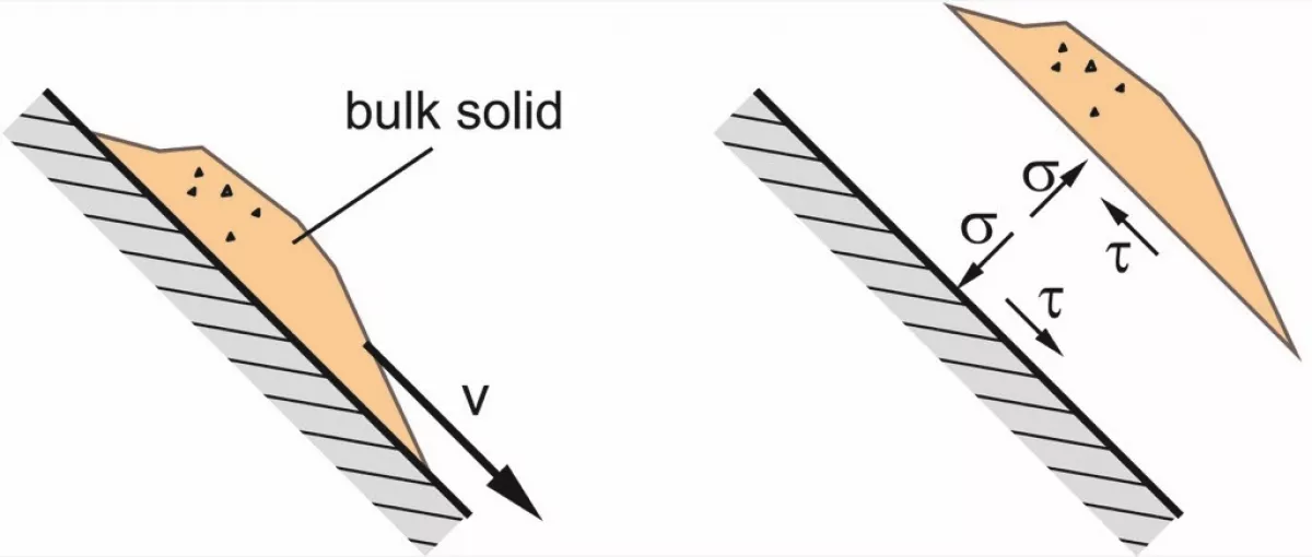
A bulk solid is composed of individual particles which are solid bodies. Thus, friction of bulk solids is expected to be similar to friction of solid bodies. An example is the solid body shown in Fig. 2.a, e.g., a wooden block, which remains at rest on the inclined plane if the static friction is not overcome. In the same manner an element of bulk solid will behave (Fig, 2.b). In both cases – solid body and bulk solid – a certain shear stress, τ, is acting between the wall surface and the solid body, or bulk solid element, respectively, resulting from the so-called downhill force. This behavior illustrates that a bulk solid can transfer friction, and, thus, shear stresses, even in a state of rest. Therefore, the bulk solid behaves completely different from a Newtonian liquid where a shear stress can exist only in the presence of a shear rate.
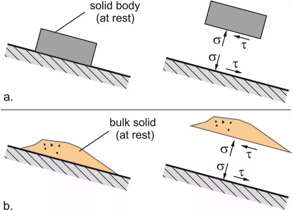
Also, shear stresses are present within a bulk solid – even if the bulk solid does not flow. In Fig. 3.a a block (a rectangular cuboid) of consolidated bulk solid is shown, e.g., a block of slightly compacted moist sand. To simplify matters, the weight of the bulk solid is neglected. A small force, F, is acting on top of the block through a piston thus creating a small vertical compressive stress, σ1, within the bulk solid. This stress shall be so small that it does not overcome the compressive strength of the compacted bulk solid. On the lateral walls of the block no stress is acting, i.e., the normal stress, σ, in all horizontal directions is equal to zero. (The atmospheric pressure does not influence the stress in the bulk solid because it acts on all sides of the particles.)
Since the block of bulk solid is force balanced even if subjected to the small force F, in all inclined cutting planes, e.g. cutting plane E, a shear stress must act (Fig. 3.b). Otherwise, the bulk solid would slide downwards along the inclined cutting plane.
2. Mohr Stress Circle
On the block of bulk solid (Fig. 3.a) different stresses are found in different directions. An established means to describe the stress distribution is the Mohr stress circle known from strength theory. Applying equilibrium of forces in x- and y-direction on the situation shown in Fig. 3.a, it can be shown that the pairs of values of normal and shear stress of all cutting planes perpendicular to the x-y-plane form a circle – a Mohr stress circle – in a σ-τ-diagram (Fig. 3.c). The center of the stress circle is located on the σ-axis. Every point of the circle represents the stresses in one particular cutting plane within the bulk solid. Since the stress circle intersects with the origin of ordinates, there must be cutting planes where both normal and shear stresses are equal to zero. This is the case for all vertical cutting planes, e.g., on the lateral surfaces of the block of bulk solid (Fig. 3.a) where no stresses are applied and, thus, both normal and shear stress are equal to zero.
The Mohr stress circle’s right intersection with the σ-axis represents the stresses in horizontal cutting planes where the maximum normal stress is acting due to the external vertical load. This greatest normal stress is called the major principal stress, σ1, while the smallest normal stress at the left intersection of the circle with the σ-axis is called the minor principal stress, σ2. The stresses acting in each particular inclined cutting plane are represented by one particular point of the stress circle. e.g., point E represents cutting plane E. (More detailed information on the application of the Mohr stress circle in bulk solids theory can be found in [1, 2].)
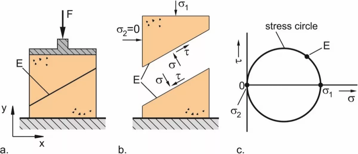
If a bulk solid is stored in a container with vertical walls, e.g., the vertical section of a silo, the resulting stress conditions are slightly different to Fig. 3.c due to the influence of the lateral walls (Fig. 4). In the vertical section of a silo the bulk solid is compressed in the vertical direction by its own weight (gravitational force). For reasons of simplification, in Fig. 4.a the force of gravity is replaced by a vertical force, F, and the walls are assumed to be frictionless. In horizontal direction the bulk solid is not deformed (neither expansion nor compression) if the lateral walls are ideally stiff and exactly vertical, too.

When a bulk solid is compressed in only one direction, i.e., there is no deformation in the perpendicular direction (so-called uniaxial compression), the major principal stress is acting in the direction of compression, and the minor principal stress is acting perpendicular to the major principal stress. Thus, the horizontal stress, σh, in the specimen shown in Fig. 4.a is smaller than the vertical stress, σv. Since the wall is frictionless (simplifying assumption), there are no shear stresses acting on the wall, and the stress distribution is represented by the Mohr stress circle depicted in Fig. 4.b. The major principal stress, σ1, found at the right intersect of the stress circle with the σ-axis, is equal to the vertical stress while the minor principal stress, σ2, is equal to the horizontal stress. Similar to Fig. 3, in inclined cutting planes which are represented by points of the stress circle above and below the σ-axis, shear stresses are unequal to zero (τ ≠ 0).
The reason for different stresses in different directions is the ability of a bulk solid to transfer shear stresses even if the bulk solid is in a state of rest. In contrast to this, a Newtonian liquid cannot transfer shear stresses in a state of rest and, thus, normal stress (or fluid pressure, p) is the same in all directions. Therefore, the stress circle representing the pressure in a liquid at rest is a point (circle with radius equal to zero) on the normal stress axis at σ = p.
Applying the conditions of Fig. 4 on the stresses within the vertical section of a silo leads to the result that the horizontal stress is smaller than the vertical stress. However, in a real silo the friction between the bulk solid and the walls cannot be neglected. This applies even for situations where the bulk solid does not flow but is stored at rest since the bulk solid is compacted already while the silo is filled and, thus, moves a bit downward along the silo walls. The latter mobilizes friction between bulk solid and wall, i. e., shear stresses develop between silo wall and bulk solid. Since the shear stress at the silo wall is unequal to zero, the stress at the wall is not represented by the minor principal stress (left intersect of stress circle with σ-axis) as in Fig. 4, but by a point on the Mohr stress circle which is, depending on the magnitude of the friction at the wall, more or less distant to the σ-axis [1, 2]. However, in the vertical section of a silo the horizontal stress is smaller than the vertical stress, irrespective of the effect of wall friction.
3. Most important Bulk Solid Properties for the Assessment of Stresses
For calculations of stresses in the vertical section of silos the ratio of the horizontal stress, which is acting normal to the wall (wall normal stress), and the vertical stress (more accurate: mean vertical stress over entire cross-section) is used. This ratio, known as lateral stress ratio, K (or λ [3]), is dependent on the bulk solid. The K-values of most bulk solids are in the range of 0.3 to 0.6 [4, 5]. They can be measured with a “Lambdameter” (Fig. 5), where a cylindrical specimen is subjected to a vertical stress, σv, while the horizontal stress, σh, is measured [4, 5, 6].
![Fig. 5: Principle of a lambdameter [4, 5, 6].](https://www.bulk-online.com/sites/default/files/public/styles/basic_max/public/2023-10/wp_2245.jpg.webp)
Knowing lateral stress ratio, K, the stresses in the vertical section of a silo can be examined in greater detail. In Fig. 6 a horizontal slice of infinitesimal height dz cut out of the bulk solid in the vertical section is shown.
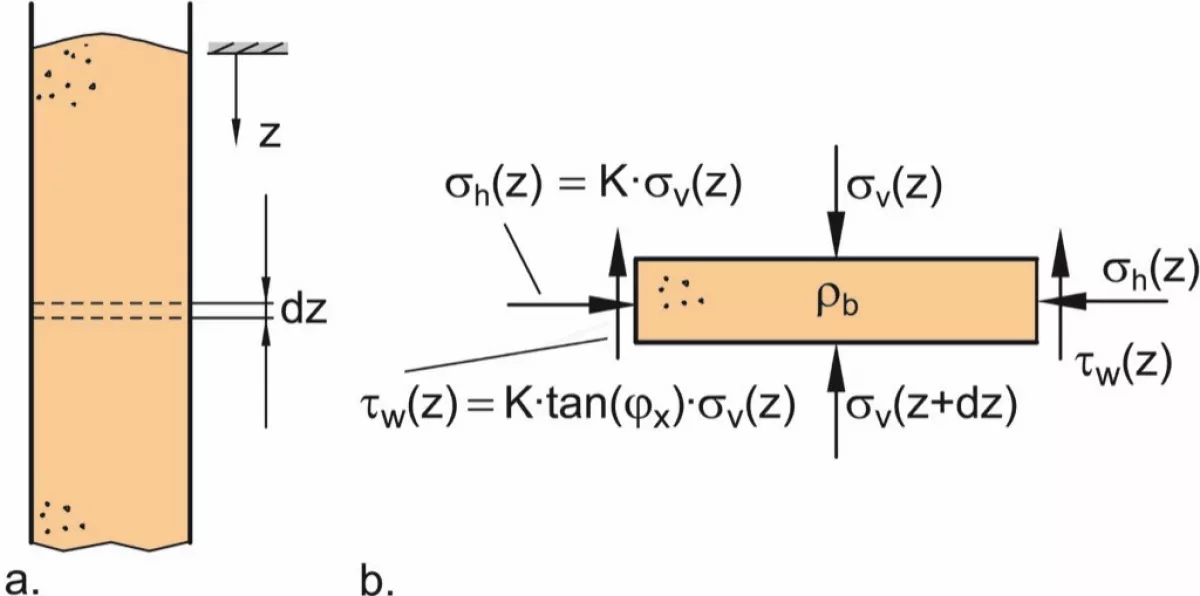
It is subjected to a vertical stress, σv(z), which results in the (smaller) horizontal stress, σh(z). With the known lateral stress ratio, K, the horizontal stress can be calculated:
| (1) |
Another important quantity is the already mentioned wall friction. It causes the shear stress, τw(z), acting upwards on the slice of bulk solid (Fig. 6.b). In the simplest case the friction between wall and bulk solid behaves like the well-known Coulomb friction between solid bodies (Fig. 7.a) where friction force, FR, is equal to normal force, FN, multiplied by the coefficient of friction, µ. This results in a proportional increase of friction force with normal force.
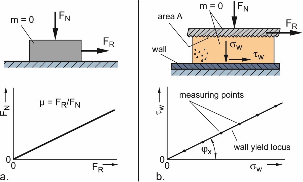
In case of a bulk solid, stresses rather than forces are regarded (Fig. 7.b). Normal force, FN, and friction force, FR, are divided by the specimen’s cross-sectional area, A, in order to obtain normal stress, σw, and shear stress, τw, acting on the wall surface. Wall friction is measured quantitatively by applying constant normal stress on the bulk solid specimen, and then moving the specimen across the wall material until constant shear stress develops. This is repeated with different levels of normal stress. Finally, the pairs of values of normal stress and constant shear stress are plotted in a σw-τw-diagram. A line or curve running through these points is called a wall yield locus. In the simplest case the wall yield locus is a line running through the origin as shown in Fig. 7.a for Coulomb friction.
The coefficient of friction, µ, is defined by the ratio of shear stress to normal stress:
 |
(2) |
In bulk solids technology the wall friction angle, ϕx, is more common than the coefficient of friction. The relationship between these two quantities is as follows:
 |
(3) |
If the wall yield locus is a line running through the origin, the wall friction angle is constant and equal to the slope of the wall yield locus (Fig. 7.b). Otherwise, the wall friction angle is a function of the normal stress, σw, and has to be calculated with Eq. (3) for the normal stress being relevant for the application under consideration.
The wall friction angle as explained above represents kinematic friction, but is applied not only to kinematic but also to static conditions though, e.g. to describe the friction between the bulk solid at rest and the silo wall. This simplification may be allowed because the friction at the wall is mobilized by the compaction of the bulk solid during the filling process and, as a consequence thereof, the movement of the bulk solid relative to the silo wall.
If the wall friction angle of a certain combination of bulk solid and wall material is known, the wall shear stress, τw(z), as depicted in Fig. 6.b, can be calculated from the wall normal stress. For this, Eq. (3) is solved for τw. Then wall normal stress, σw, is replaced by horizontal stress, σh, acting in the vertical section of the silo, and wall shear stress, τw, is replaced by the shear stress at the silo wall, τw(z):
| (4) |
After introduction of Eq. (1), the shear stress at the wall can be calculated directly from the vertical stress with the help of the two material-dependent quantities K and ϕx:
| (5) |
The considerations above show that all stresses acting on a slice element in the vertical section of a silo are dependent on the vertical stress, σv (see Fig. 6.b). These fundamental relations were published already in 1895 by H.A. Janssen [7] and are still part of most silo codes on the assessment of silo loads (e.g., [6]).
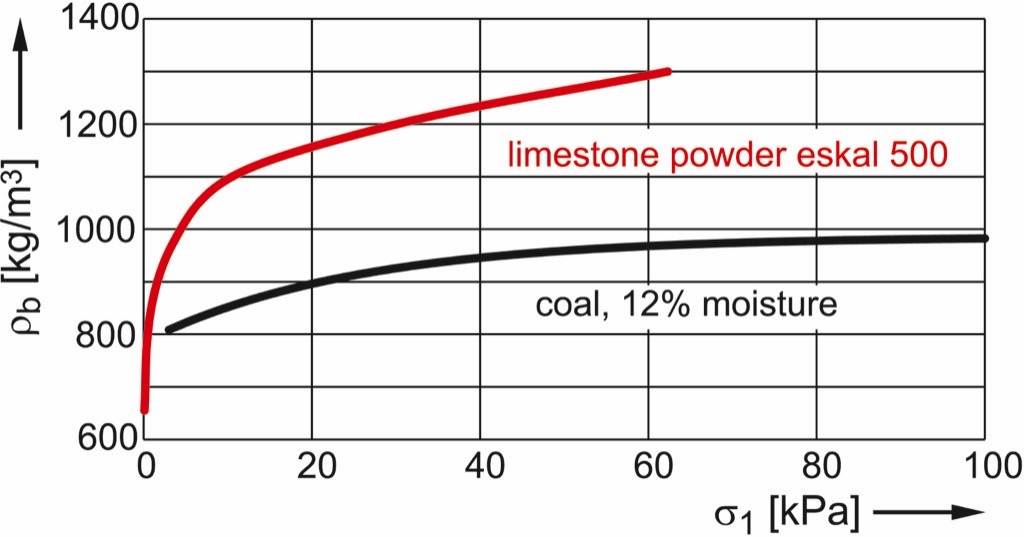
Another value with high impact on the stresses in a silo is the bulk density, ρb. Bulk density is material dependent, but is also a function of the state of compaction and, thus, dependent on the stresses acting on the bulk solid. The sensitivity of bulk density on stress is low for most free-flowing bulk solids (dry, coarse), but can be very strong for cohesive materials (moist, fine-grained). The latter is demonstrated by Fig. 8 showing functions of bulk density versus stress of a fine limestone powder (mass median x50,3 of about 4 µm) and moist coal (12 mass percent moisture, particle size “0” to 10 mm).
A realistic calculation is only possible if a realistic value of the bulk density is used. A meaningful value is the bulk density which results from the stresses acting at the position under consideration [8]. One can obtain the bulk density as a function of stress (as shown in Fig. 8) from measurements with shear testers (yield locus tests [1, 2]), or from compressibility tests where a specimen in a test setup similar to the Lambdameter (Fig. 5) is subjected to an increasing vertical stress. The bulk density is then determined from the mass of the specimen and its actual volume.
The poured density, which is obtained by filling a certain amount of bulk solid in a small lab-scale test container, or the tapped density, which is the bulk density obtained through a compaction process, often combined with vibration or shocks (what does not happen in a common silo), should be judged critically regarding application to stress calculations: The loose density takes place only at the tip of a silo filling where the stress is small, but is usually smaller than the bulk density deeper in the silo. Thus, stresses are underestimated when calculating the silo based on the loose density. The opposite may happen if the tapped density is applied because it can be clearly larger than the density which can be achieved in a silo.
4. Janssen’s Investigations on Stresses in a Silo’s vertical Section
At the end of the 19th century the engineer H.A. Janssen living in Bremen, Germany, faced the task to design silos for the storage of grain which was imported from overseas. It was known that silos for grain storage had been built in the United States, but not in Europe where appropriate procedures for structural design were not available.
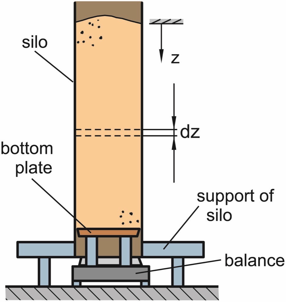
Therefore, Janssen started model tests (Fig. 9). Model silos with square cross-section of different size were placed above a balance which carried the bottom plate of the silo while the silo itself was carried by a support placed on the ground. Thus, the vertical stress acting on the bottom plate was measured for different filling levels. This way Janssen could confirm that the vertical stress is not proportional to the filling level, or mass of filling, respectively (Fig. 10). The vertical stress at the bottom increases less and less with the mass of filling and finally approaches a constant value.
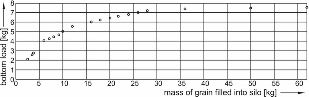
Janssen varied the silo’s cross-section and the wall roughness. He found that for large filling levels the vertical stress at the bottom was the smaller, the smaller the cross-section and the greater the wall roughness [7].
5. Janssen ’s Approach
To obtain an equation for the calculation of the stresses acting in the vertical section of a silo, Janssen set up an equilibrium of forces on a slice of bulk solid of infinitesimal height dz, cross-section A, and perimeter U (Fig. 11).
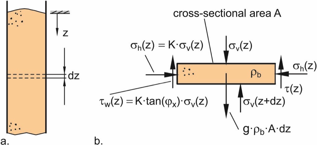
Top and bottom of the slice are subjected to the vertical stress, σv. Further, the weight of the slice (g · ρb.·A · dz) and, as a result of the friction between bulk solid and silo wall, the shear stress, τw, acting upwards on the lateral surface (U · dz) of the slice are taken into account.
| (6) |
with
| (7) |
and the dependence of shear stress on lateral stress ratio, K, wall friction angle, ϕx, and vertical stress, σv, as outlined in Section 3 (Eq. (5))
| (8) |
a differential equation can be derived:
 |
(9) |
If the differential equation is solved considering the boundary condition of the vertical stress being equal to zero on top of the bulk solid filling, i.e., σv(z = 0) = 0, the result is:
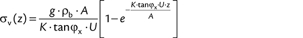 |
(10) |
With this equation both horizontal stress, σh, and shear stress, τw, can be easily calculated because σh = K · σv and τw = K · tanϕx · σv (Eqs. (1) and (5)).
The exponential function approaches zero for infinite depth, z, since its exponent is negative. Thus, for z → ∞ Eq. (10) becomes:
 |
(11) |
Index ∞ indicates that the stress is valid for z → ∞. In many real silos the stress σv∞ is nearly attained already in a depth, z, of two to three times the diameter, D (more about this topic follows in Section 7).
A closer inspection of Eqs. (10) and (11) shows the influence of the involved quantities:
- Stresses increase with increasing bulk density, ρb.
- Larger ratios A/U result in larger stresses. For a cylindrical vertical section with diameter D it follows A/U = D/4. Thus, in silos with greater diameter, D, and large filling levels, stresses are higher than in silos with smaller diameter.
- Larger wall friction angles, ϕx, and larger lateral stress ratios, K, result in smaller vertical stresses because the bulk solid is supported by higher shear stresses, τw, acting between silo wall and bulk solid. Thus, a larger part of the bulk solid’s weight is carried by the silo walls.
The asymptotic approximation of the vertical stress to a constant value (σv∞) can be explained by a simple consideration: The larger the vertical stress, the larger the horizontal stress (= wall normal stress) acting on the wall of the vertical section, and, thus, the higher the shear stress transferred between wall and bulk solid (according to Coulomb’s law, shear stress is proportional to normal stress). If the vertical stress is sufficiently high, the vertical force resulting from the wall shear stress (τw · U · dz) is equal to the weight force of a slice of bulk solid (g · ρb · A · dz), i.e., the slice of bulk solid is completely supported by the wall friction acting on its perimeter. Therefore, the vertical stress does not increase further if equilibrium of friction force and weight force is attained:
| (12) |
For the sake of completeness it should be mentioned that this equilibrium can be derived also from Eq. (6) for constant vertical stress, i.e., σv(z) = σv(z + dz).
Replacement of the shear stress in Eq. (12) by Eq. (8) results in:
| (13) |
Solving Eq. (13) for the vertical stress, σv, which is in the case under consideration equal to the constant vertical stress, σv∞, attained in infinite depth, z, results in Eq. (11).
6. Stresses in the vertical Section
Janssen’s approach allows the calculation of stresses in a silo’s vertical section (It cannot be applied on hoppers because due to the inclined walls the conditions are different, e.g. the ratio of horizontal to vertical stress [1, 2]). In Fig. 12 calculated functions of vertical stress, σv, horizontal stress, σh, and wall shear stress, τw, are plotted over the height of a cylindrical section of diameter D = 3 m. The relatively large height of the cylinder which is ten times the diameter was chosen to demonstrate the approximation of the stress functions to their final values.
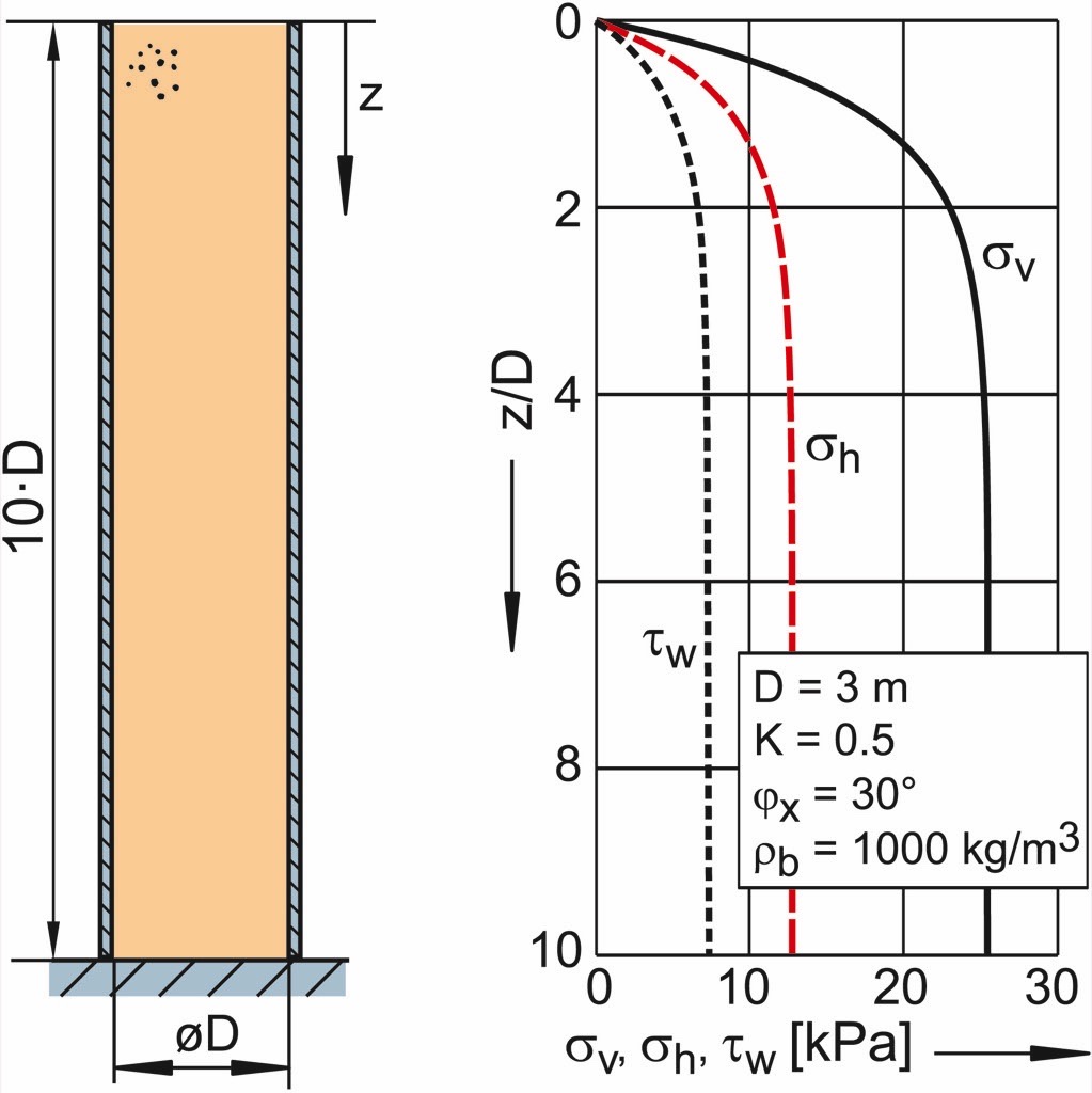
The highest stress in the diagram of Fig. 12 is the vertical stress, while the horizontal stress is only half the amount because of K = 0.5. The shear stress, which results from the horizontal stress multiplied by the tangent of the wall friction angle (ϕx = 30°), is even a bit smaller. The graphs of the three stresses are similar to each other because of their proportional interrelationships. For the set of parameters given in Fig. 12, the stresses attain a nearly constant level at a depth z = 4 D (z/D = 4), and the major part of the stress increase takes place in the range z/D < 2.
7. More detailed Examination of the Stresses
To study the influence of individual quantities, more calculations are presented in the following. Hereto the vertical stress is represented as dimensionless number which is obtained by dividing it by the vertical stress attained in infinite depth, σv∞. This way Eq. (10) becomes
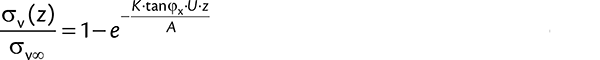 |
(14) |
The dimensionless vertical stress in Eq. (14) is independent of bulk density. Further, the ratio of cross-sectional area, A, and perimeter, U, is expressed with the hydraulic diameter, Dh, known from fluid mechanics:
 |
(15) |
Introducing Eq. (15) in Eq. (9):
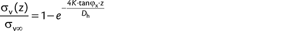 |
(16) |
In case of a cylindrical vertical section, the hydraulic diameter, Dh, is identical to the cylinder’s diameter, D, which can then plugged in Eq. (16) instead of Dh.
In Fig. 13 the influence of the wall friction angle on the vertical stress in a cylindrical vertical section is illustrated. On the left diagram the vertical stress resulting from the given quantities bulk density, lateral stress ratio, and cylinder diameter is plotted. Starting from the top of the filling, where the vertical stress is zero, the vertical stress increases downwards. The greater the wall friction angle, the quicker the vertical stress approaches its final value, σv∞. As already outlined in Section 5, the larger the wall friction angle, the smaller the final value, because with increasing wall friction angle a larger part of the bulk solids weight is carried by the silo walls. In case of (very rarely occurring, but already observed) extremely small wall friction angles (here ϕx = 1°) the bulk solid is only marginally supported by the silo wall with the result that the vertical stress increases almost linearly. If the bulk solid’s properties such as the wall friction angle have not been measured prior to the design of the silo, a very small wall friction angle may lead to unexpected large loads, e.g., on a hopper located underneath a vertical section.
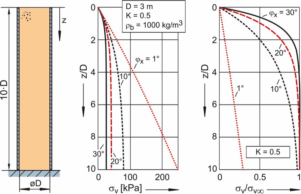
The right-hand diagram in Fig. 13 shows the dimensionless vertical stress (according to Eq. (16)). One can see very clearly that the vertical stress approaches its final value σv/σv∞ = 1 the quicker, the greater wall friction angle, ϕx.
In Section 5 it was stated that in many cases the vertical stress is almost constant already in a depth, z, in the range of two to three times the silo diameter, D. This is illustrated by Fig. 14 where coordinate z(distance to the top of the bulk solid filling; here represented by the dimensionless ratio z/D) representing the level where 90 % of the final vertical stress , σv∞, is attained, is plotted over the wall friction angle, ϕx, for different values of the lateral stress ratio, K. As already discussed with respect to Fig. 13 also in Fig. 14 it is clearly visible that an increasing wall friction angle, ϕx, results in a quicker approximation of the final value, σv∞ (quicker approximation means that 90% of σv∞ are attained already at small ratios z/D). The same tendency can be observed with increasing values of the lateral stress ratio, K.
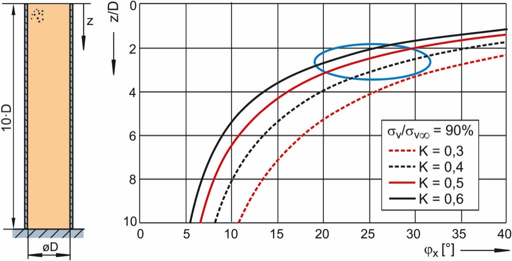
The ellipse drawn on the diagram (Fig. 14) indicates the range of wall friction angles and lateral stress ratios which are found relatively often with real bulk solids. In this range the ratio z/D is about 2 to 3. This means that for these bulk solids the vertical stress attains 90% of the final vertical stress, σv∞, already in a dimensionless depth z/D of 2 to 3. The example of Fig. 12 falls in this range, too.
8. Loads on the Walls of the vertical Section
The bulk solid in the vertical section is supported by wall friction. Thus, a part of the bulk solid’s weight force is transferred to the silo wall. The shear stress, τw, as indicated in Fig. 11, acts upwards on the bulk solid, and downwards on the silo wall. As a consequence, a vertical force, Fwv, is induced in the silo wall. For the case that the vertical section is supported from its bottom (as in Figs. 12 and 13), the vertical force is transferred through the silo wall towards the bottom.
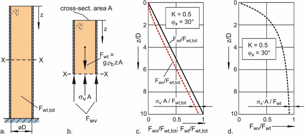
To calculate the vertical force in the silo wall, Fwv, the wall shear stress, τw, has to be integrated along the silo wall. With the already presented solution of Janssen’sapproach the force in the wall can be determined based on a simple equilibrium of forces. Thereto, the vertical section is cut at an arbitrary value of z (cross-section X in Fig. 15.a) and a free-body diagram is drawn for the part above cross-section X (Fig. 15.b). Following forces have to be taken into account:
- Weight force, Fwt(z), of the bulk solid above cross-section X. Assuming constant bulk density, Fwt(z) is equal to (g · ρb · z · A).
- In cross-section X the vertical stress, σv(z), multiplied by the cross-sectional area, A, is acting on the bulk solid. σv(z) is calculated with Eq. (10).
- The vertical (compressive) force, Fwv(z), acting in the wall.
Equilibrium of forces in z-direction results in:
| (17) |
Eq. (17) indicates that the vertical force in the wall at a position z is the result of the weight force, Fwt(z), of the bulk solid above this position minus the force transferred by the bulk solid through the vertical stress, σv(z). On the diagram of Fig. 15.c the weight force of the bulk solid, Fwt, and the vertical force in the wall, Fwv, are plotted over the dimensionless coordinate, z/D. The forces are converted to dimensionless values by dividing them by the weight force of the total filling of the vertical section, Fwt,tot. At the bottom (here at z/D = 10) the ratio Fwt/Fwt,tot is equal to one. The ratio Fwv/Fwt,tot representing the vertical force in the wall is not much smaller than Fwt/Fwt,tot since the difference results according to Eq. (17) only from the vertical stress in the bulk solid (see difference σv·A/Fwt,tot indicated in Fig. 15.c).
In Fig. 15.d the ratio of the vertical force in the wall to the weight force of the bulk solid, i.e., Fwv/Fwt, is plotted over the dimensionless coordinate, z/D. With increasing distance to the top of the filling, this ratio (Fwv/Fwt) increases and approaches one. The reason is that the vertical stress, σv, approaches its final value with increasing depth, z (see Fig. 12). Thus, while the weight force, Fwt, increases with increasing z according to Eq. (17), the expression σv(z) · A can attain at maximum the value σv∞ · A. Therefore, with increasing depth, z, the vertical force in the silo wall, Fwv, approaches the weight force of the bulk solid, Fwt. Simply put, in a high, slender silo the bottom part of the vertical section’s walls carries nearly the entire weight of the bulk solid within the vertical section. However, it has to be said that this simple statement is not a general one, e.g., if wall friction is extremely low (e.g., Fig. 13 for ϕx = 1°), the statement would be correct only for non-realizable height/diameter ratios.
Summary of Part 1
In the present first part of the paper on stresses in silos the behavior of bulk solids being relevant for the calculation of stresses is discussed. Important characteristics are the dependence of stresses on the orientation, and the quantity of the shear stress at the wall of a silo’s vertical section. The relationship between vertical stress, horizontal stress, and shear stress at a wall can be described with two material-dependent quantities, namely lateral stress ratio, K, and wall friction angle, ϕx. These quantities can be measured with appropriate test equipment. The weight of the bulk solid being the origin of the stresses acting in silos is taken into account by both the material and stress dependent bulk density, ρb.
Furthermore, Janssen’s approach for the calculation of stresses in the vertical section of a silo was outlined. With this approach, which is the base of many codes for the assessment of silo loads for structural design (e. g., [6]), the load on the lateral walls of the vertical section, and the stresses in the bulk solid, too, can be calculated. However, in most codes additional safety factors and different operating conditions are taken into account to obtain a safe design. The influence of wall friction and the height/diameter ratio was illustrated by calculation examples.
| About the Author | |
| Prof. Dr.-Ing. Dietmar Schulze
Prof. Dr.-Ing. Dietmar Schulze, born in 1959, is Professor at the Institute for Recycling of the Ostfalia University of Applied Sciences since 1996. He is co-founder of the consultancy Schwedes + Schulze Schüttguttechnik GmbH (silo design, powder testing) and founder of Dr. Dietmar Schulze Schüttgutmesstechnik (development and manufacture of ring shear testers for powder testing). |
■

