
(From the archive of ”bulk solids handling", article published in Vol. 32 (2012) No. 2 , ©2012 bulk-online.com)
Advances and changes have been occurring rapidly in all aspects of explosion protection. When selecting advances or changes, several criteria come to mind, i.e., since when have the advances been introduced, what are the base technologies improved and what are the benefits and added values that resulted from the change, and are they worth the cost, complexity, etc? Regarding the time of introduction, no real attempt will be made to place a time limit on the topic. Rather, the limit will be more of the significance of the advance.As prelude, it may also be helpful to recognize some of the causes and driving forces for these advances and changes. some examples are:
- new fuels (hydrogen, bio-fuels), hazards (nano-particle technology) or hazardous conditions,
- continuous drive for efficiency (higher temperature, pressures; operations closer to flammability limits),
- heightened awareness of explosion hazards and the need for improved safety; cost of downtime, or
- competition and a globalised market.
The change in hazards has generally lead to more challenging protection requirements, an example being the projected increase in the use of hydrogen as a fuel. Such explosions are notoriously difficult to protect against, yet the increased usage makes this an important and relevant challenge. Nano-particles may represent a new hazard due to the largely unknown effect upon explosibility parameters and the ability to apply protection measures.
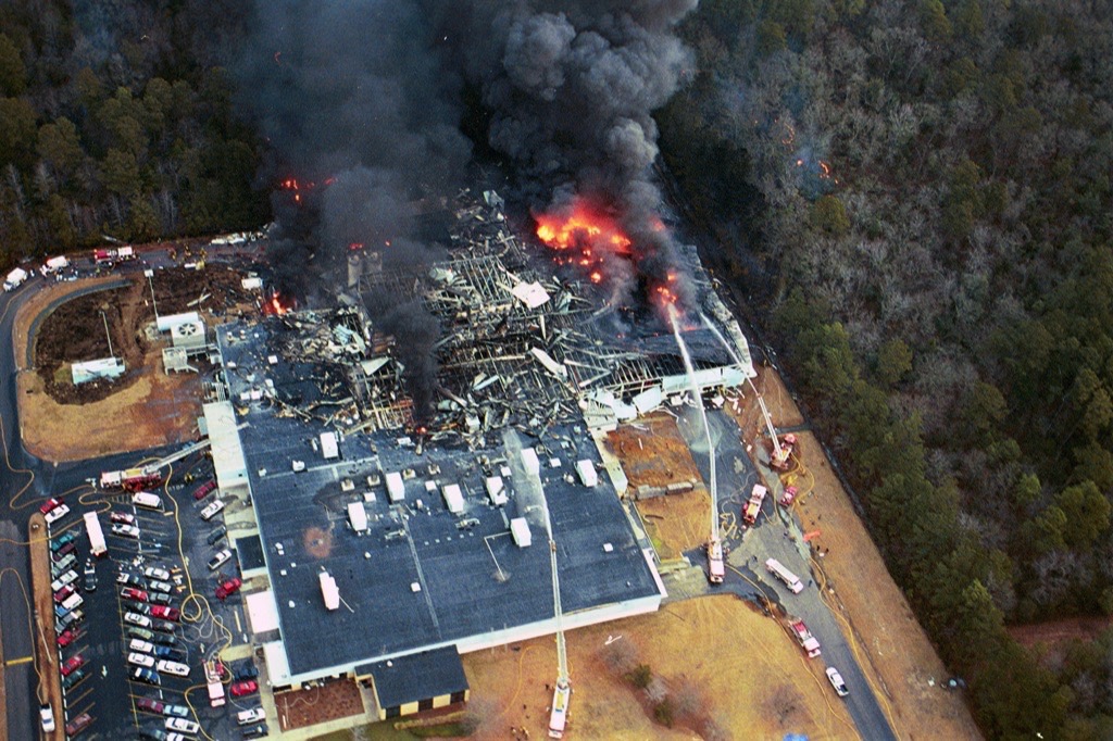
The continuous drive for increased efficiency can lead to more hazardous operating conditions; higher temperatures and pressures, processes closer to flammability limits, etc. This may create hazard scenarios more difficult than addressed by current standards and protection methodologies.Recent, well publicized industrial explosions have resulted in a much greater public and corporate awareness of the consequences of an accident. In turn, the demand for protection solutions has driven improvements and additional options.What then are the technologies and related areas that will be considered? The chart in Fig. 2 shows six areas where advances and changes have been significant.
Deflagration Science
Many of the advances in this area have been international and can be found in literature, symposium proceedings and journals. A particularly active area has been in the use of sophisticated computational techniques for modelling and predicting behaviour.The seminal product is probably the computational fluid dynamics based program termed FLACS (Gexcon). This has been successfully applied to gas explosions and more recently the methodology has been extended to work with dust explosions (DESC). While still in development, it has promise of becoming a useful tool for modelling deflagrations as well as protection efficacy. Potential benefits include more efficient large scale tests, non-standard protection designs and post-explosion diagnostics. Other computational programs such as EFFEX (Ineris) are actively being developed.Another area of wide interest is a better understanding of turbulence, turbulent burning velocities and laboratory measurements of explosibility parameters. As a beginning, NFPA 68 has recognized that very high turbulence will affect Kst and change vent area requirements. Similar interest exists in the effect of low turbulence conditions. Eckhoff [1] reminded of the significant effect of ignition location and turbulence on deflagration development within large vented silos and noted that suppression would benefit from a more basic design involving advanced numerical simulation codes.
Explosion Detection
The first step in any active explosion protection system is detection. While many of the major improvements are based on the combination of detection and control, the detector itself is the starting point. A developing deflagration generates pressure and radiation and the detection of either can be used as the indication of an impending explosion. Pressure detection has been used almost predominately although the use of optical detection, discussed later, is increasing. Initially, a mechanical switch type device was used for pressure detection. For the purpose of detecting an incipient explosion on an active process, the switch had many problems:
- response could be 'slow' and variable,
- limited to static activation,
- no output signal other than activation,
- no supervision of contact integrity,
- spring-based mechanism requires frequent re-calibration,
- sensitive to orientation,
- sensitive to vibration and shock.
In short, they lacked speed, provided no information, were not highly reliable and where unstable. The key advancement was made when mechanical switches were replaced with active transducers; devices that continuously converted mechanical energy (pressure) into electrical energy (an output signal). These are often referred to as analogue detectors and are based generally on a thin metal or ceramic membrane in contact with the process. Small changes in pressure on the membrane cause slight movements which in turn result in changes in resistance (metal diaphragm) or capacitance (ceramic diaphragm). The result is a continuous output signal that is proportional to the pressure applied to the membrane. Features of this type of transducer which represent the key advances are shown in Table 1.
| Feature | Characteristic |
| High sampling frequency | Up to 5000 per second |
| Fast response | < 1 millisecond |
| Corrosion resistant membranes | Ceramics, SST, Hastelloy C |
| Continuous signal | Available for processing and decision making |
| Insensitive to orientation | Ceramic |
| Wide functioning range | Typically ±0.6 to 1 bar |
| Vacuum tolerant | Full vacuum |
| Over pressure tolerant | 4 to 12 bar |
| Hygienic | Sealed flush membrane |
| Long term calibration stability | |
| Improved shock and vibration resistance | |
| Wide temperature range | ~215 °F/~100 °C on process |
Optical detection in conjunction with pressure detection provides several advances in protection design. The radiation of a spark at one extreme or a flame front at the other extreme allows detection that often would not be possible with pressure detection. Sparks particularly would not contribute to pressure and would be un-detected. The advantage of optical detection is also its disadvantage; it responds to radiation in general. This requires that the system be isolated from any ambient radiation or is able to differentiate flame radiation from ambient radiation. Most optical detectors currently respond in the near IR or IR region and thus require this shielding.Key advantages are the ability to respond to very low levels of radiation, e.g., sparks and the ability to detect a flame front faster than a pressure detector. This last case is exemplified by certain isolation scenarios. A deflagration occurring in a large enclosure with a relatively low Kst will require considerable time to develop a detectable pressure. When ignition is close to an interconnection, flame can start propagating through that ductwork. If pressure detection is “slow”, the flame front can accelerate and reach a connected vessel or achieve high velocities and potentially transition to detonation. Optical detection at that interconnection however will respond to the first appearance of flame and allow isolation to be effective. On the other hand, optical detectors are not suited for enclosure detection due to obscuration of the radiation.
System Controllers
The advanced pressure transducers provide data but the control unit is where the next major advances have been made (see Table 2).
| Feature | Benefit |
| Syncronise to real time | Compare to process data |
| Maximum pressure warning | Adjustable level; max value captured; indicates loss of process control |
| Minimum pressure warning | Adjustable level; min value captured; indicates loss of process control |
| Pre- and port activation pressure history | Data and graphs available for diagnosing cause of activation |
| Static and rate based activation | Adjustable levels |
| ANDing requirements | Improved stability |
| Continuous pressure available | On-demand readout of process pressure |
| Supervision of input and output signals and circuitry | Provide ‘trouble’ signal when problem detected; alerts personnel; initiates corrective action |
| Activation settings | On-site modification |
| Long term calibration stability | |
| Improved shock and vibration resistance | |
| Wide temperature range | ~215°F/~100°C on process |
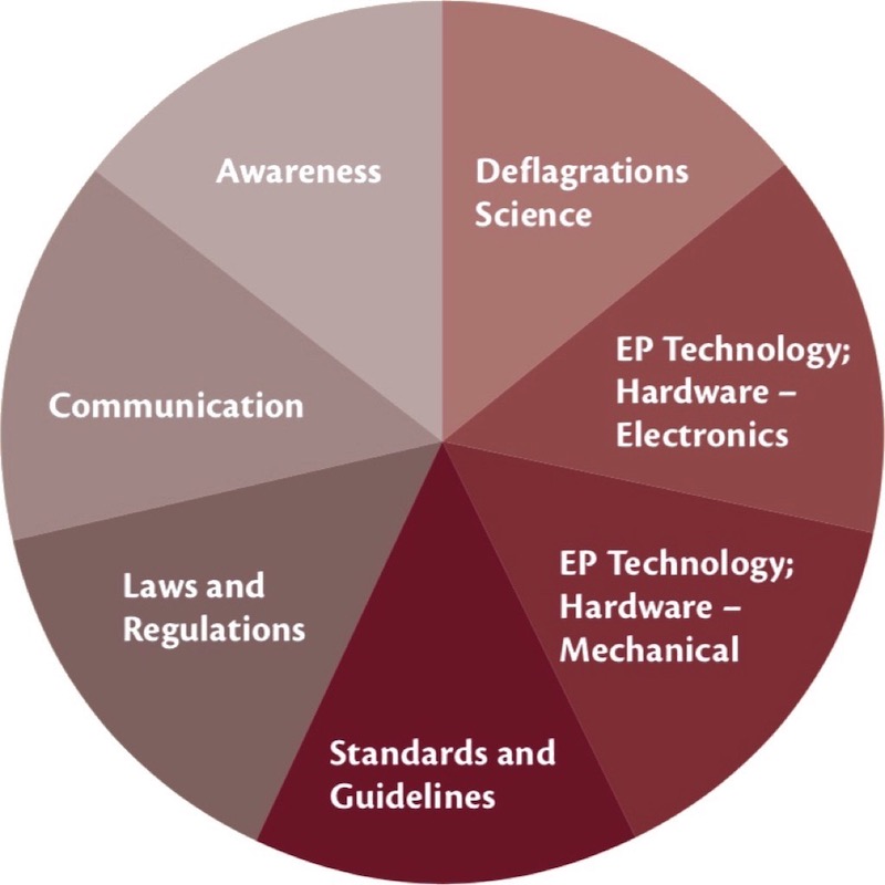
The existence of a continuous pressure signal allows interpretation and documented decision making. The new controllers are based on high speed micro-controllers and have the capability to capture and analyse the data before making an activation decision. Much of the value gained here is not only in sensing an actual explosion, but in discriminating against non-explosions and preventing un-intended activations. False signals can result from electrical spikes, particle impacts on the detector face, process pressure changes, etc. Signals can be filtered and compared in order to make a decision. A key example is the ANDing of two detectors on the same process. By requiring both detectors to indicate an activation pressure simultaneously, the likelihood of activation from particle impact, for example, is greatly reduced.A continuous pressure signal can also be used for warning purposes. Warning signals result when the pressure exceeds a pre-set level, lower than the activation pressure, but indicates a problem in the process. Product build-up on a detector face, for example can eventually result in activation. Such warnings can also be used to indicate low operating pressure conditions.In the event of activation, the process pressure history before and after the activation time, can be captured for review. Detailed process data of several hundred milliseconds duration and process trend data of several seconds can be captured (see Fig. 3). This data has significant value in diagnosing the event and verifying the cause of the activation. It also records that time of activation which can be matched with other process data.
Mechanical Protection Technology
In the overall process of designing an explosion protection system, a decision will have been made about the protection objective. The objective selected by the owner/operator is matched with the appropriate technology as shown below. Active systems generally rely on detection and control described above while passive systems do not.
| Protection objective | Protection technology | Mode |
| Control pressure and flame | Suppression | Active |
| Containment | Passive | |
| Control flame | Venting | Passive |
| Control flame propagation | Isolation | Active or passive |
Flame Suppression
Suppression is based on extinguishing the propagation flame front by physical (heat absorption) or chemical methods. The mechanism of suppression is related to the type of agent used; dry powder such as sodium bicarbonate, clean agents such as HFC 227, or the early agent of choice, Halon 1011. Regardless of the agent, the key to successful suppression is the rapid delivery of sufficient agent to terminate the combustion process. Key advances in suppression include:
- technologies geared to rapid delivery (e.g., discharge orifice size and pressure, replacement of explosive devices, use of gas generating devices),
- passive devices such as foams and expanded metals, and
- safety and reliability improvements such as lock-outs and pressure monitoring
The overall delivery of agent to the flame front is affected by how quickly the dispersion begins, how fast the delivery is, and the quantity of agent delivered. The initial event in dispersing the agent is the opening of a 'valve'. The speed of delivery once the valve has opened is controlled by the driving pressure and the flow restriction. Pre-charged containers use pressures between 34 and 65 barg with higher delivery velocities at the higher pressures. Flow restriction depends on the size of the valve opening (orifice) and the nozzle. Fig. 4 shows the expected increase in velocity as the orifice is increased. Containers charged at 65 barg and with larger openings clearly provide the fastest delivery rate.
The valve commonly used is a form of a rupture (bursting) disc with a means of causing it to open rapidly.Historically, explosive charges and small detonators (squibs or blasting caps) were used to cause opening. While fast, these devices required annual replacement and now have regulatory restrictions. Their use has been largely discontinued.One change has been the use of a gas generating devices to delivery a shock wave which opens the rupture disc valve. These devices with 5 to 10 year replacement cycles maintain the opening speed while eliminating the use of explosives. Other forms include a mechanical valve having a hinged plate that is released by the action of a non-explosive linear actuator and a double disc valve whose opening is also initiated with a linear actuator. Gas generation has been used on a larger scale to actually create the gas pressure inside a discharge container that is initially at atmospheric pressure. The rapid generation of gas is used to discharge the agent into the protected area.A new and unusual form of passive suppression protection is the use of expanded metals or polymers foams in an open volume that could contain gaseous fuel. An example would be the ullage volume of a fuel tank on an airplane. The device behaves essentially like a flame arrestor and serves to terminate flame propagation.Two concerns about the use of pressurized agent containers has been the potential injury to personnel exposed to the discharge and the failure to discharge due to loss of pressure. Both issues are addressed in the relevant industry standards. The applicable lockout/tag-out regulations prohibit personnel from being exposed to stored energy.
New devices and techniques are now being employed to actively block stored energy release as well as prevent the arming of suppression systems in the blocked configuration Fig. 5). Unknown and undetected loss of pressure in a container lowers system reliability. Although these containers have routinely been fitted with mechanical indicators, access to these containers is often difficult and routine inspection may suffer. Today’s systems may use real-time pressure monitoring interlocked to control panel which can annunciate low pressure conditions and ensure system integrity.
Venting Solutions
The second protection option is venting, that is, the control of pressure by release of the deflagration through an opening of the appropriate size. The closure, vent panel, door, etc. opens at pressure pre-determined to prevent damage to the enclosure. Venting may well be the first intentional form of explosion protection. Some of the original closures were made of metal sheets, plastic sheets, composites, etc. While able to release the deflagration pressure, they all suffered in not having predictable release pressures (Pstat), good quality control, vacuum resistance, pressure cycle tolerance, low mass, etc. All of these limitations work against being able to accurately predict final enclosure pressure (Pred). Many also reduced venting efficiency requiring extra area to achieve the required reduced pressure. Now, manufactured vent closures are subject to extensive quality control and have predictable performance. Single panel closures have less weight which improves efficiency; new designs allow high vacuum operating conditions, higher temperature, cycling and pulsing, as well as meet hygienic requirements. For example the prescriptive sections of NFPA 68-2007 include a number of significant advances in the vent area calculation.The most notable advance in venting in recent years has been flameless venting. It is well recognized and stipulated in relevant industry standards that indoor venting is discouraged. At the same time, due largely to the new awareness of dust explosion hazards, many existing processes are being reviewed for protection. Many of these are located within buildings which restricts the use of conventional venting.
Flameless venting becomes an attractive alternative to suppression. Flameless venting merges the well established technology of venting with flame arresting and controlled particle retention. The fire ball exiting through the vent opening is required to pass through flame arresting elements and particle retention mesh. The end result is the prevention of flame release and the retention of particles at the expense of efficiency. By using additional vent area, based on large scale testing and agency approvals, indoor venting is a proven, safe alternative. Fig. 6 illustrate the difference between open venting and flameless venting.While venting is a reliable, cost-effective method of preventing damage from pressure, it does not affect flame. One consequence can be a residual fire in the dust collector, silo, etc. Often, these vessels are equipped with fire extinguishing system utilizing inert gases such as CO2 or N2. However, the vent opening allows the extinguishing gases to escape and oxygen to enter, making it more difficult and costly to control the fire.
A recent advance has been the inventing of a reclosing low mass vent. The vent closure behaves normally during the release of pressure, but once it has passed, the nature of the closure material returns it to its original position.The residual opening is about 5 per cent which now permits fire suppression to be effective. Fig. 7 shows the vent position as it begins to open, when it is open and after the flame and pressure have been released (approx. 500 milliseconds) when it has returned to its original position.
Isolation Devices
A non-technological advance in isolation that should be mentioned first is the increased recognition of the need for isolation in conjunction with suppression, venting or even containment. A process without interconnections is rare and any process with interconnections is subject to flame propagation through the ductwork. This is recognised in the ATEX directives and the latest revisions of the NFPA Standards. For example, NFPA 654 states in 7.1.4.1 “Where an explosion hazard exists, isolation devices shall be provided to prevent deflagration propagation between pieces of equipment connected by ductwork”. Some of the technical isolation options are listed in Table 4.
| System | Type | Fuels | Flame isolation | Pressure isolation |
| Chemical barrier | Active | Dust, gas | Yes | No |
| Mechanical: Gate | Active | Dust, gas | Yes | Yes |
| Mechanical: Pinch | Active | Dust, gas | Yes | Yes |
| Mechanical: float | Active | Gas | Yes | Yes |
| Passive | Gas | Yes | Yes | |
| Diverter | Passive | Dust, gas | No | Yes |
Only a few technical advances have happened in recent years. Gas generators described above are now being used as the primary closing force for several types of mechanical valves, replacing pressurized gas containers. An increased interest in passive valves and diverters has been seen and a CEN standard for Flame Diverters/Explosion Decouplers or Diverters has been drafted.
Standards and Guidelines
Significant changes have been made in the past decade in the development of industry standards and guidelines. The standards provide a clear definition of responsibilities, emphasizing the requirements for record keeping, inspection, maintenance, and training, management of change, and the role of performance based designs. In general the industry standards have greatly expanded technical sections with specific performance requirements.
Regulatory and Related Activities
A strong regulatory state exists and expands in the European Community. The regulations and standards commonly referred to as ATEX impose safety and performance requirements on both the process industries as well as the safety equipment industry.The closest thing to an actual regulatory change in North America has been the National Emphasis Program (NEP) instituted by OSHA in 2007 and 2008. While not necessarily a change in the law, the NEP has resulted in an increased awareness of dust explosion in the process industry. The U.S. Chemical Safety Board does not have regulatory authority, but has conducted an extensive review of dust explosions and made a number of strong proposals for regulatory reform.Following the Imperial Sugar explosion in 2007, an effort was made to change safety regulations. House Bill 5522 was passed and sent to the senate which was unable to act prior to the end of the session. This bill has been reintroduced as HR 849, “The Worker Protection Against Combustible Dust Explosions and Fires Act”.
Communications and Awareness
Many positive advances have been made in communicating the hazard and consequences of dust explosions. This has included the publications and symposia of professional organizations as well as governmental groups and is international in scope. Examples of symposia and related activities held in the past few years include the AIChE Global Congress on Process Safety, the NFPA Dust Explosion Symposium (this meeting), the International Symposium on Process Hazards and Mitigating Industrial Explosions, CSB Hearings, Reports and Videos, and many more.
Conclusion
Explosion protection techniques have been undergoing several refinements as a result of the implementation of legislative requirements and the innovative developments of products by suppliers. The extended use of explosion protection standards and demands from industry users for best practice solutions has not only resulted in additional products with improved performances but has also triggered an in-depth awareness stimulants with law- and standards makers, educational/testing institutes and Health and Safety Inspectorates. Further increases of knowledge and products are eminent, offering additional and better solutions to the users.
A Note from the Editor
For all statements in this article that refer – directly or indirectly – to the time of publication (for example “new”, “now”, “present”, but also expressions such as “patent pending”), please keep in mind that this article was originally published in 2012.
References:
- Eckhoff, R.E.: Understanding dust explosions – The role of powder science and technology. Journal of Loss Prevention in the Process Industries, Vol. 22 (2009) No. 1, pp. 105–116.
| About the Authors | |
| FirstName LastNameDepartment Company, Country | |
| FirstName LastNameDepartment Company, Country |
■

