
When it comes to drive sizes exceeding 3500 kW per individual drive, there are no conventional drives with electric motors and helical bevel gears. Gearless drives, like those implemented for mine hoists in underground mining operations, allow the use of larger drive units and are increasingly being utilized to drive belt conveyors.
Introduction
Individual belt conveyors in hard rock mining operations all over the world nowadays extend over distances of more than 16 km and overcome height differences of up to 500 m, while normally achieving outputs of approx. 12000 t/hr. Such belt conveyors have had a significant impact on the development of individual components. Conveyor belts with strength of up to 7800 N/mm are actually in use today. In South American copper mines such belts are driven by electromechanical drives, consisting of electrical motors (wound rotor or squirrel cage motor) and helical bevel gears with a capacity of up to 3150 kW each. The performance requirements of belt conveyors are redefined by lower ore contents and deeper deposits. Nowadays conveyors are routed through tunnel systems such that the maximum length available is required in order to reduce the number of underground transfer stations. This places higher demands on the quality and strength of the conveyor belts. Today, the St 10.000 with strength of 10000 N per Millimeter of belt width is available. An alternative for continuously improving belt quality with ever-increasing drives located at both ends of the conveyor is to optimize the application of drive forces on the belt. Possible alternatives include:
- Belt on belt drives (TT-drives)
- Intermediate drives in the top strand and/or bottom strand
- Motorized carrying rollers [1]
Unfortunately it is not always possible to implement such advanced drive concepts. For driven carrying rollers, for example, there is still no cost-effective and reliable solution. That’s why the current development projects focus on adapting conveyors with the traditional head and/or tail pulley drive systems to new challenges and demands. Takraf is currently (article published in 2014, Ed.) involved in studies that focus on a belt conveyor system that utilizes St 10000 belts. The limits of conventional drives with helical bevel gears are exceeded with the required drive capacity of 21000 kW per individual conveyor. Low-speed synchronous motors, like those frequently implemented as drive solution for mine hoists in underground mines, permit larger drive capacities. As part of the above-mentioned study, a conveyor is equipped with three gearless drives of 7000 kW each.
Gearless Drives – Maintenance and Efficiency
The advantages of gearless drives compared to electromechanical drives cannot be reduced to the possibility of installing larger drive units alone. The curve of the motor’s efficiency in relation to the motor’s torque shows over the entire spectrum values that are higher than the characteristics of traditional conveyor drives with asynchronous wound rotor or squirrel cage motors completed with gears (Fig. 2).
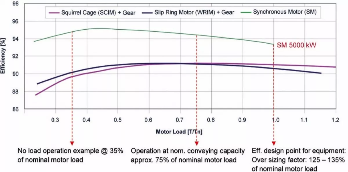
Furthermore, belt conveyors do not always work at full load over the entire period of operation. Partial load conditions and even (short-term) idle periods are all part of a belt conveyor’s operating regime. In contrast to asynchronous motors, the efficiency of synchronous motors increases in the range of partial load (Fig. 2). The higher efficiency of synchronous motors in general and especially in the partial load range and the fact that mechanical loads are eliminated during transfer of torque lead to lower operating costs for the conveyor. The maintenance of the gear unit including oil change intervals can be omitted just like the maintenance of the high-speed coupling. This is of particular interest wherever maintenance processes involve considerable effort. Prime examples of this would be operating conveyors in Canada at ambient temperatures of -45°C or conveyor systems set up at an altitude of 4500 m and more above sea level, such as in Chile.
Structure of Gearless Conveyor Drives
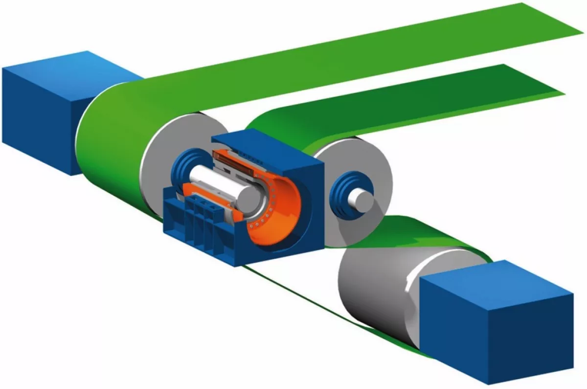
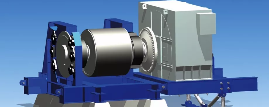
A synchronous motor consists of a rotor that is connected with the drive pulley shaft and a stator that rests on a foundation or a corresponding steel structure (Fig. 3).
Compared to conventional belt conveyor drives, the drive unit with gear box and asynchronous motor is replaced with a synchronous motor. The following conditions must be taken into consideration if gearless drive systems are used:
- Deflection of the drive pulley shaft at the shaft end due to varying belt tensions at the different load and operating conditions.
- Possible settling of the stator foundations or deformation of the steel structure used to support the stator.
- Possibility for readjusting the entire drive in case of belt misalignment during commissioning.
A prerequisite is the need to comply with the permissible deviations in the motor’s air gap. Since the design of the motor, motor mount, drive pulley and the associated steel structure are closely tied together, Takraf entered into a cooperation agreement with ABB. This agreement allows to select a joint motor concept already during component planning, considering client specifications as well as site conditions. The following systems are worth considering as a motor concept:
- Bearingless motor: The rotor is directly connected to the drive pulley shaft (by means of a flange connection), whereas the stator of the drive motor is supported separately.
- Motor plus separate bearing: The rotor has two bearings. The stator is secured to the foundation or steel structure.A flexible coupling facilitates the transfer of torque between rotor and drive pulley.
- Diaphragm coupling: Compared to the motor with separate bearings, the motor mount on the output shaft side and the flexible coupling is replaced by a diaphragm coupling.

