(From the archive of ”bulk solids handling", article published in Vol. 33 (2013) No. 1 , ©2013 bulk-online.com)

Prominent Fluid Controls, Australia, has supplied more than 60 fluoridation systems over the past 25 years. Many of the earlier installations were for rural water supplies in smaller water treatment plants. Initially, 25 kg bags of sodium silicofluoride powder (Na2SiF6) were manually loaded into a hopper; later installations used a vacuum loader designed by Prominent. A dry chemical feeder meters the powder into a mixing tank of water, where it is dissolved before being added to the water supply. Other chemicals used for fluoridation are sodium fluoride powder and hydrofluosilicic acid.
Toxic Dust Control
More recently, however, the company has supplied equipment for much larger plants, including five that started up in Queensland around the end of 2008. The plants range in size from approx. 125 to 750 million 1/d and serve more than 50% of Queensland's population.
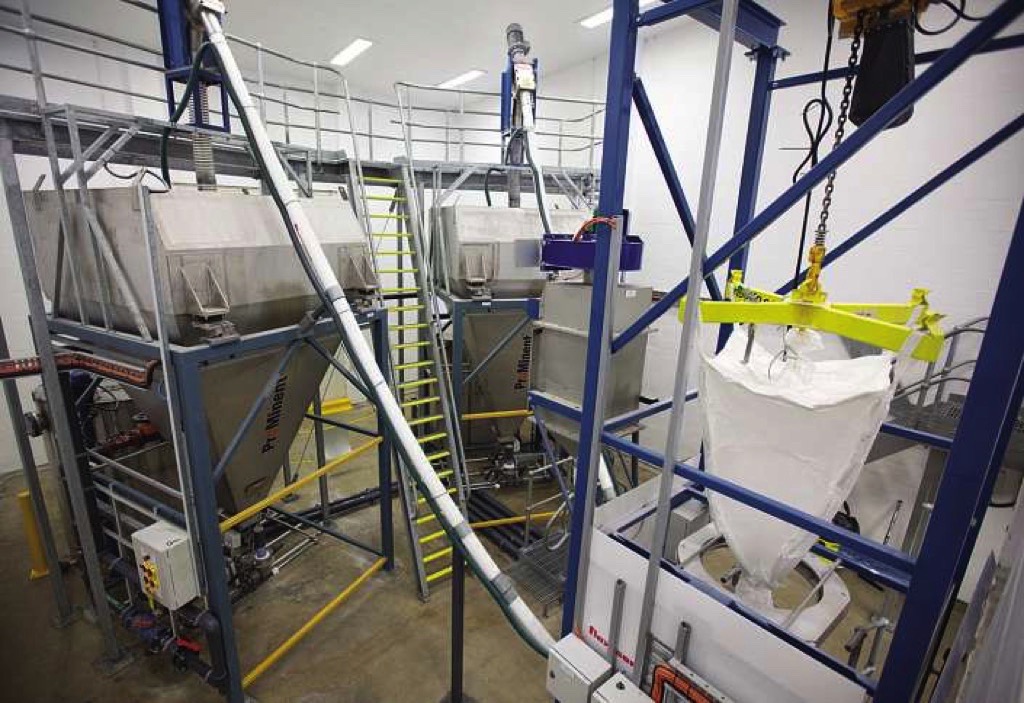
For plants of this size, Prominent has designed a fully automated process in which the Na2SiF6 is completely contained in a sealed transfer system from the time it is received until the moment it is put into the mixing tank. Sealing is important for dust control, because the plants use up to 87 kg/d of Na2SiF e which is toxic and subject to strict regulatory control. Bulk bags of Na2SiF6 are unloaded into a transition or floor hopper, from which a flexible screw conveyor transfers the material to a storage hopper that feeds the mixing tank. The transition hopper is small, with a capacity of only 60 I. In contrast, storage hoppers may be as large as 8750 I or more for a 750 million 1/d plant, and designed to hold up to seven days supply of Na2SiF6.
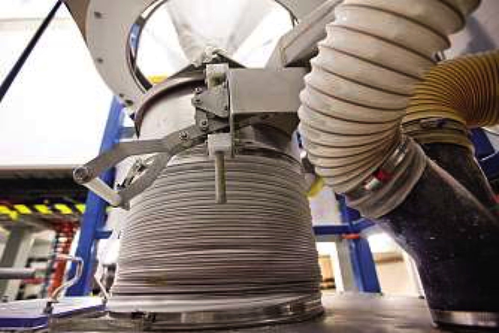
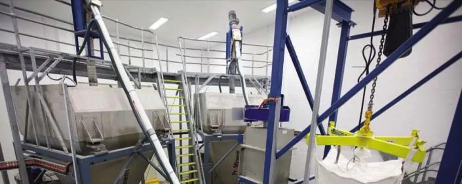
The major pieces of equipment are the bulk bag discharger, a dust containment system, and the flexible screw conveyor, all supplied by Flexicon. Bulk bags of 1000 kg are lifted into place on the discharger frame by an electric hoist and trolley on a cantilevered I-beam. Powder is discharged from the bag into the transition hopper through a double-wall TeleTube telescoping tube. The tube is secured to the bag spout by a patented SpoutLock clamp ring that creates a dust-tight seal, while the bottom of the tube is connected to a collar in the lid of the hopper.

The clamp ring, in the open position, is raised pneumatically to the bag spout. The spout is pulled over the rim of the tube's inner wall and the ring is locked in place over it. At this point the pneumatic pressure that raised the tube is released, causing the telescoping tube assembly to exert downward pressure on the spout. The continuous downward pressure on the bag keeps the spout taut at all times and helps maintain a steady flow by preventing excess material in the spout from bulging outward and creating dead spots, or falling inward and restricting the flow.
Flexicon's Bag-Vac dust collection system is activated prior to connecting the telescoping tube to the bag. The system, attached to the discharger frame, conveys dust pneumatically to a water trap tank. Once the clamp ring has been secured, the dust extractor is turned off and the spout drawstring is untied, allowing the powder to flow into the transition hopper.
The dust extractor remains inactive throughout the unloading process. However, air displaced by the flow of material exits via the dust collection system. A filter prevents Na2SiF6 from being entrained in the outflowing air.
Stopping the Flow is a Cinch

A special feature of the unloader unit is a pneumatic Power Cincher flow control valve that can close the bag at any time, so that a partially empty bag can remain in place until more material is needed. This is important for the fluoridation plants, which use approximately 120 kg/d of Na2SiF6 per 100 million litres per day of water. The cincher also helps to keep moisture out of the bag and can isolate the bag in the case of an emergency.
Promoting flow are Flow Flexer bag activators two pneumatically driven plates that rhythmically raise and lower opposing bottom edges of the bag to direct material to the outlet. As the bag empties, the stroke of the plates lengthens, forming the bag into a steep V-shape and promoting total evacuation. An adjustable timer controls the frequency of the strokes.
The dust tight system is vented to a BagVac dust collector that removes residual powder and collapses the empty bag prior to tie off, preventing dust generated when empty bags are flattened manually.
A Self-Centred Conveyor
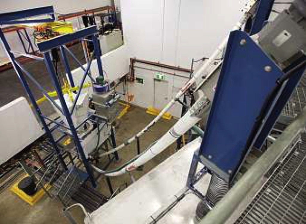
A flexible screw conveyor transports the Na2SiF6 from the floor hopper to a storage hopper that feeds the mixing tank. The conveyor consists of a rotating, stainless steel spiral screw, housed in a 65 mm diametre polymer tube. The lower end of the roughly 5 m long tube passes through the wall of the floor hopper, near the bottom, and the top end discharges the powder through a chute into the top of the storage hopper some 4.5 m above plant floor.
As the screw rotates, it self-centres within the tube, providing ample clearance between the screw and the tube wall to prevent grinding of the product. A 4.0kW electric motor, located above the discharge point, rotates the screw at a variable rate up to 6000 kg/h.
As the bag's contents empty into the floor hopper, the conveyor is activated. The transfer of powder to the storage hopper continues until either the transition hopper is empty or the weight of the storage hopper reaches a preset high level. The control system signals the conveyor to stop when the high level is reached.
The Final Stages
From the storage hopper, a dry chemical feeder meters the fluoride powder into a mixing tank through a sealed unit that prevents the escape of dust. The flow of powder is automatically matched to the inflow of water to the tank in a ratio that results in a 0.2 percent Na2SiF6 saturated solution. The tank has a high-speed mixer and a retention time of 10 min.
Finally, the solution is carefully metered into the flowing water supply by a peristaltic pump (or a progressive cavity standby pump). The dosage rate varies from 0.6 mg/I to 1 mg/I, depending on local requirements.
In rare cases a water treatment plant may have two independent pipelines, each with its own dosing system. This situation occurs, for example, when a town or city has grown and added more treatment capacity. These cases require separate storage hoppers and dosing systems for each pipeline. However, a single bulk bag discharger and one transition hopper can feed two storage hoppers by incorporating two separate flexible screw conveyors into the single common transition hopper. Feeding two storage hoppers is well within the capacity of the system.
A Note from the Editor
For all statements in this article that refer – directly or indirectly – to the time of publication (for example “new”, “now”, “present”, but also expressions such as “patent pending”), please keep in mind that this article was originally published in 2013.
■


