
The analysis of the optimal conveying method begins with understanding system and material variables such as: energy requirements, bulk density of material, purchasing and storage of material prior to use, conveying distance, space and location, and durability and maintenance. These are just a few of the many elements that must be considered in conveyor selection and design.
Pneumatic conveying is often a standard solution for processing facilities conveying dry bulk product. While pneumatic conveying has advantages in specific applications, a totally enclosed tubular drag conveyor can offer similar advantages, while also providing:
- Custom engineered designs that meet specific plant layout requirements, inlet and discharge points and flow rate.
- Gentle conveying of highly degradable materials, yet durable for mineral and mining material handling.
- Minimal long-term maintenance with patented air-over-hydraulic auto tensioner that automatically maintains chain tension for reliable and consistent flow.
- Variable frequency drives that mitigate energy usage spikes and reduce overall power requirements.
- A fully enclosed conveying system that does not introduce air into the material stream, reducing dust ignition risk.
- Low energy consumption.
Tubular Drag Technology
The tubular drag conveyor consists of a stationary outer housing, usually round in shape, through which a chain is pulled by a sprocket drive. Flights are attached to the chain at regular intervals. As the looped chain and flight assembly moves through the stationary housing, bulk material is pulled from the in-feed points to the discharge ports.
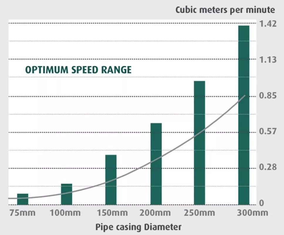
Conveying capacity is established by varying the housing size, distance between flights, and the chain speed. The stationary outer housing, or casing, is manufactured of carbon steel or stainless pipe in sizes ranging from 76 up to 304 millimetre diameter. Fig. 2 represents the intersection of optimal size and flow for effective movement of material. Casing sections are supplied in lengths as required by the predetermined conveyor path. To provide for a change in direction, the casing is formed into a sweep elbow.
Product discharge points are engineered where needed in the conveyor layout. The discharge gates, like the chain and flight assembly configurations, are important conveyor design considerations. Traditional knife or slide gate valves are sometimes used in tubular drag designs but are not the most effective design for the application.
If the material is friable, a sheering affect begins to take place causing product degradation. Conveying applications such as mining and mineral processing will have failure issues related to the conveyed material characteristics if this valve configuration is used.
The large size and hard particle material moved in these applications, combined with the lack of full product discharge, will cause the gate valve to periodically fail open because the carry over will become lodged in the valve path. Furthermore, in batch applications, the carry-over will cause cross-contamination of product. For these reasons, a discharge gate specifically engineered for tubular drag conveying is highly recommended.

Fig. 3 shows a discharge gate specifically designed for tubular drag conveyors. The valve design is convex rather than flat providing a tight seal to the conveyor with no internal gap. This design allows for 100 percent material discharge when the valve is open, eliminating concerns of valve failure due to particles lodging in the valve path, or cross-contamination in batch applications.
Conveyor Layout
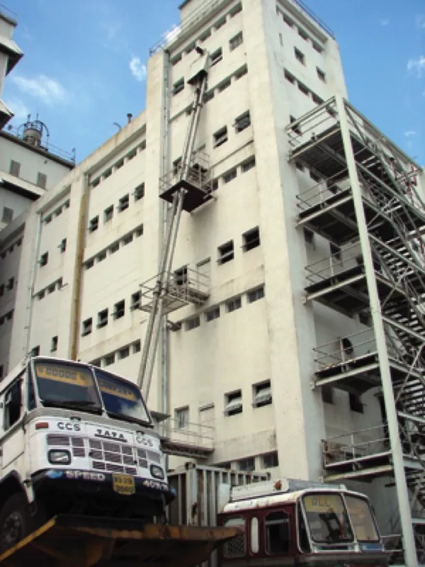
Due to the flexible chain and custom made conveying sections and casing bends, virtually unlimited variations of layouts are possible. This type of conveyor can be installed in existing facilities, bypassing obstacles that would interfere with the path of other types of conveyors.
A beneficial feature of this conveyor is the enclosed construction. This design effectively protects the product being conveyed from contamination from the outside atmosphere and/or protects the atmosphere and the worker from the product. Material can be conveyed under a positive pressure or a purge blanket of inert gas. This operating condition usually exists in applications where the conveyed material is highly absorbent and cannot have moisture or air introduced in the conveying flow. It also applies to applications where material may oxidize and cannot have air entrained in the material flow. For these situations, an inert gas is used to pressurize the system at 0.017 bar.
The moderate moving, positive displacement action of the conveyor chain assembly makes the system ideal for handling blended materials without separation and assures gentle product handling with minimal product degradation. This measured movement also assures long conveyor life, plus dependable service and operation at minimal noise levels. In addition, the rugged construction allows for conveying of hard and abrasive material in physically challenging environments.
System Integration
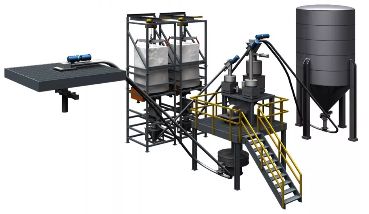
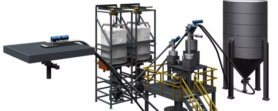
A good example is the lime milling and blending system used in many chemical processing plants (Fig. 4). In this application, several dry products are unloaded from bulk bags while a third product is conveyed from a storage silo. The raw material is brought to a loss-in-weight blending station which uses a metered feeder to accurately blend the mixture in preset ratios.
The blended product is then discharged into a grinding mill for particle reduction and final blending. A tubular drag conveyor on the discharge of the mill delivers the final product to a truck loading station where it is hauled away for packaging or bulk sale.
Conveying with Confidence
The tubular drag conveyor is a viable alternative to pneumatic conveying offering many benefits in a wide range of applications.
The core operating components of the conveyor allow for optimal conveying based on material and application factors. Particle size, bulk density, intermittent or continuous operation, volume of flow, number of unique materials to be conveyed, and obstacles or barriers the layout must overcome are all important design criteria used in the engineering of a tubular drag conveyor.
The tubular drag chain and flight configurations, materials of construction, and number and placement of inlet(s) and discharge points, are customized elements of design. The design options with the tubular drag conveyor allow for integration into a new or an existing material handling system and provide for long, reliable conveying operation.
■

