
Stockyards are used in almost every bulk material handling industry for storage of raw material and act as a buffer or mixing facility for blending of materials with differing properties prior to further processing. For new projects, operators must consider capital costs and the operational efficiency of equipment and must choose between the virtually infinite possibilities offered by the market. Homogenisers, blenders or storage only and circular or linear storage are the main decisions.
Stockyard Size and Type of Operation
The first question to ask when designing a new stockyard project is the size in terms of storage capacity. The size of the storage capacity is not just proportional to the production capacity. it results from the combination of a feed and a reclaim process and is only a synchronising buffer between two different conveying flows. Even though raw materials have generally relatively low cost per tonne, the stored quantities must not be oversized unnecessarily.
Stockyards are commonly classified into two main categories according to their shape: circular or longitudinal. Another classification is according to the general type of operation: continuous or dual pile (batch).
Circular stockyards based on dual-pile operation exist but the main advantage of the circular shape is the possibility of continuous operation whereas a longitudinal stockyard can only exist in dual-pile mode.
A dual-pile operation consists of two identical stacks for one single flow of a given commodity, with each pile being alternatively stacked while the other is reclaimed. This way the risk of interference between the stacker and the reclaimer is avoided. When one pile is full, the other one should be empty and the two machines cross each other (under strict conditions) to begin a new cycle.
There are cases where only one pile is required. This occurs if the time for rebuilding a stack is short compared to the time for reclaiming it completely. In such cases the daily bin capacity may be sufficient to cover the entirety of the rebuild time (during which no reclaim is allowed) or a by-pass option shall be provided to allow direct feed of the daily bin.
When working in the single pile mode, it is useful to have the possibility of rebuilding a partially reclaimed pile. otherwise deliveries have to be coordinated with great accuracy.
Optimal Sizing of a Dual-pile Stockyard
Most of the time storage capacity of a stockyard is defined by the longest possible interruption to the stacking operation. The question is: How long can the process go on while the stacking operation is interrupted? The answer to this question defines the size of the stockyard as the size of the buffer necessary for the synchronisation of the incoming and outgoing flows. As a corollary to that, the rate of stacking must be adapted so that the system shall never unprime.
Let's consider a case where the raw material feed is achieved from a nearby quarry or by a truck shuttle loop that operates (preferably) during daytime and possibly only on weekdays. On the other hand, the process is supposed to operate continuously. The storage acts as a buffer to cover the interruption of feed during night time and weekends and a reserve of two or three days should be sufficient.
Over-storage
Is there an advantage to have two days more ahead in stock? Over-storage is beneficial only if there is the corresponding extra feeding capacity that allows the stacker to step over the reclaimer. At the same time a larger pile is being reclaimed, a larger pile must be built.
If the quarry or the crushing is the bottleneck, it can't be balanced by a larger storage capacity. Should the two piles be empty, the reclaimer will be stopped for longer because the new pile takes longer to build. Generally speaking, larger storage capacities come at the expense of flexibility.
Another typical example is the feed from cargo ships. In this case, the size of the maximum cargo defines the maximum size of the stockyard. The rebuilding of the pile must be carried out as quickly as possible to minimise ship detention. Therefore the pile rebuild operation should not take more than a couple of days. To ensure the continuity of the process, additional capacity has to be provided to cover that period.
As a general rule the further away and the less certain the source of raw materials, the larger the stock required. A second rule is that the larger the stock capacity, the higher the stacking rate needs to be. If this is not the case, the flexibility of production will be low.
Pile Change and Daily Bin Size
With a dual pile operation, there are interruptions to the flow every time the stacker and reclaimer swap locations. Therefore some storage capacity such as a bin or silo (often called a daily bin) needs to be provided between the stockyard and the main process to keep a continuous feed.
The flow interruption time to be covered by the daily bin is not only the time necessary for the relocation of the machines itself, but also the loss of reclaimer output due to the pile-end-effect, especially with frontal reclaimers when they operate in the end cones.
Alternative Feeding Route
Stackers and reclaimers are sturdy equipment and can be maintained during annual plant stoppages. However, there is also a need to provide an alternative possibility for feeding the process to allow for situations such as a failed reclaimer, especially in case where multiple processes are fed by single stockyard line that is required to operate continuously.
The most common alternative feeding route are emergency hoppers that are fed by front loaders, which are both flexible and simple. However, where alternative feeding is for more than just emergencies, a cost effective by-pass option should be considered. This could include direct discharge by the stacker onto the reclaim belt.
Stockyards for Continuous Operation
With a continuous stockyard operation (circular stockyard) there is only one stack revolving endlessly around the centre of the stockyard either clockwise or counter-clockwise. The stacker operates at one end while at the same time the reclaimer operates at the other end of the stack. The distance between the front and tail ends is a measure of the quantity currently held in the stockyard.
If the stacker is coming too close to the back end of the reclaimer, this means the pile is full and the feed must be interrupted. The instantaneous stacking rate is always higher than the reclaiming. Therefore, the reclaimer front end shall only come close to the stacker if it has stopped.
With continuous stockyards there is no interruption for relocating piles and therefore it may directly feed a continuous process, without the need for a daily bin.
Stacking Patterns
The most common stacking pattern for storage systems that have no homogenising purpose is the cone-shell method. It is built by building a first cone with a height equal to the nominal height of the stack and then moving in one direction along a straight line for linear stockpiles or in a circle for circular stockpiles.
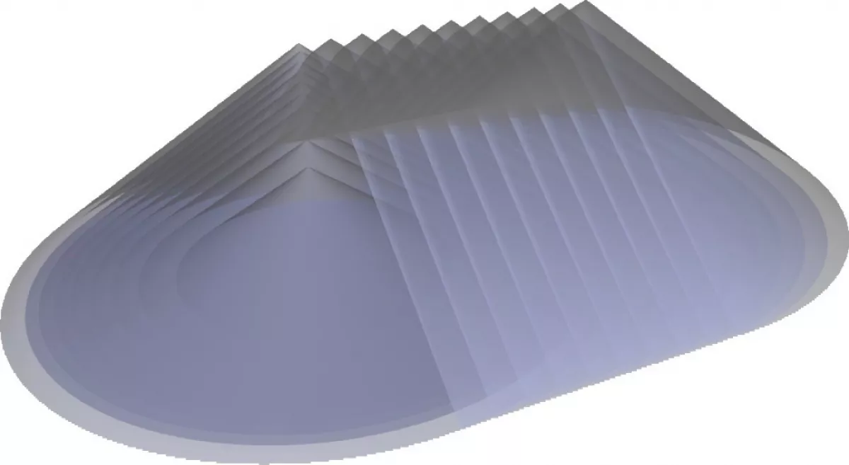
Fig. 4a: Cone shell stacking pattern.
|
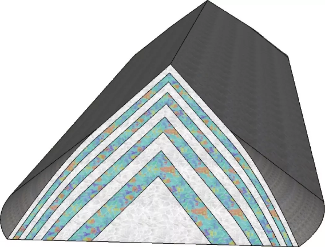
Fig. 4b: Chevron stacking pattern.
|
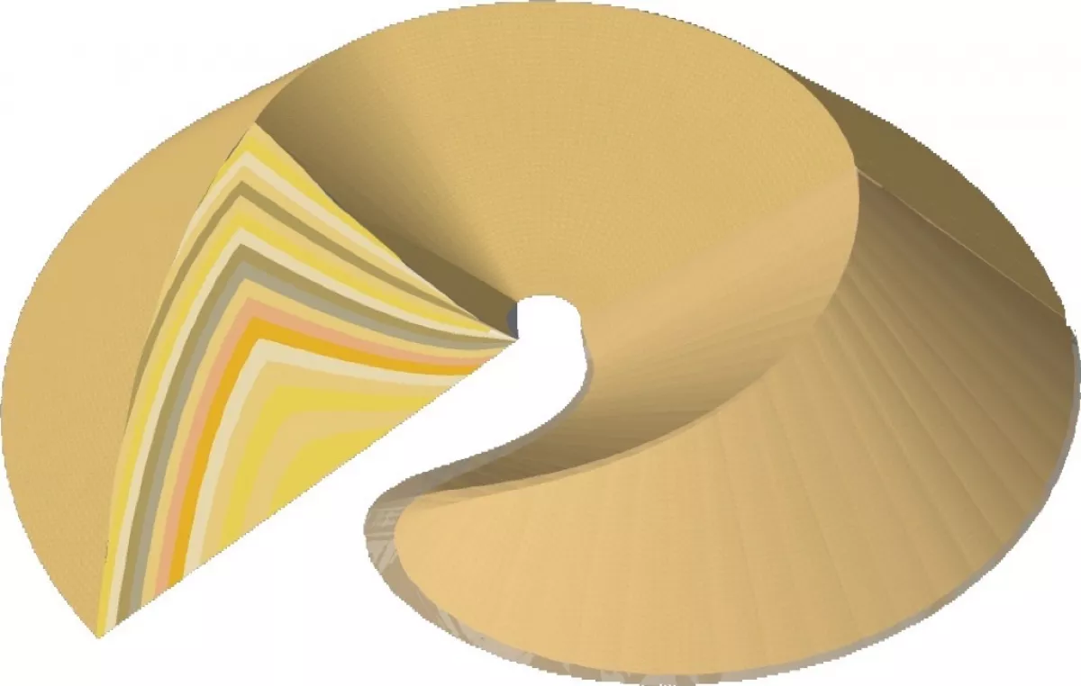
Fig. 4c: Chevcon stacking pattern.
|
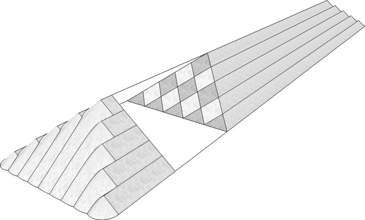
Fig. 4d: Windrow stacking pattern.
|
The chevron or "longitudinally layered pile" method can be used with circular and linear stockyards and consists in building a pile by spreading the material in layers along the centre line of the pile by travelling the stacker back and forth through the full length of the pile at a given speed. The thickness of the layer of material deposited during the process is given by the ratio between the volumetric stacking rate and the speed of the stacker travel.
The "chevcon" pattern is derived from the chevron and is exclusively suitable for circular continuous stockyards. It is like a chevron applied only to the tail end of a circular pile where each layer is shifted one after the other, always in the same direction. The result is a parabolic shaped crest called the construction ramp of the pile. The slope of the crest is mild near the top and increases toward the lower end. If it were a pure parabolic shape it would end in a vertical slope, but as it is limited to the natural angle of repose of the material it ends in a cone. Chevcon is the invention of an engineer of the original German company PHB, which unites the ideas of a combination of chevron and cone shell.
Windrow stacking is similar to chevron but the position of the axis along which the material is deposited by the stacker is changing (by e. g. rotation of the stacker boom). This results in cords being piled up in a pyramidal way.
The Problem of Segregation
One important side effect of stacking is the well known effect of segregation, by which the bigger lumps tend to roll downhill while the finer material remains on top of a stack. Segregation becomes all the more inconvenient when the grain size heterogeneity may follow an equal chemical heterogeneity, like for example with compound materials. Gypsum is a typical example where purity can vary significantly from bigger lumps to finer material.
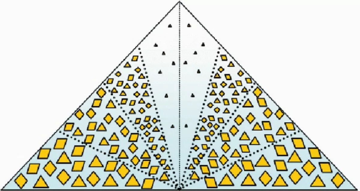
In some cases, segregation is handled through the reclaiming process but windrow is the stacking pattern that best prevents this phenomenon from developing.
Reclaiming Modes
There are two different ways of reclaiming: frontal and side. If frontal reclaiming can be compared to cutting slices from a cake, side reclaiming could be compared to slicing up a potato into crisps.
Frontal reclaiming consists of bringing the material down following a cross section of the pile. The resulting output rate is the product of the cross sectional area by the speed of progression through the pile.
Side reclaiming consists of taking a pass of only a small portion of the cross section, most of the time of triangular shape, along the whole length of the pile, before cutting the next pass until the pile is empty. The resulting output rate is the product of the cross sectional area of a pass multiplied by the speed of travel.
Side reclaimers are characterised by their lifting scraping boom. Various examples are shown below. The most common frontal reclaimers are bridge type with harrow raking systems. Other types include side reclaimers running in "pilgrim pace" mode and overhead excavators (ladder type) that are run on walls.
Stockyards for Homogenisation
Bed storage can achieve homogenisation, providing low extra capital expenditure compared to mere storage. Combining a specific stacking pattern and a specific reclaiming method, it is possible to a certain extent to shuffle a given amount of a material to obtain a significant reduction in the variations of its characteristics, as measured by defined quality parameters.
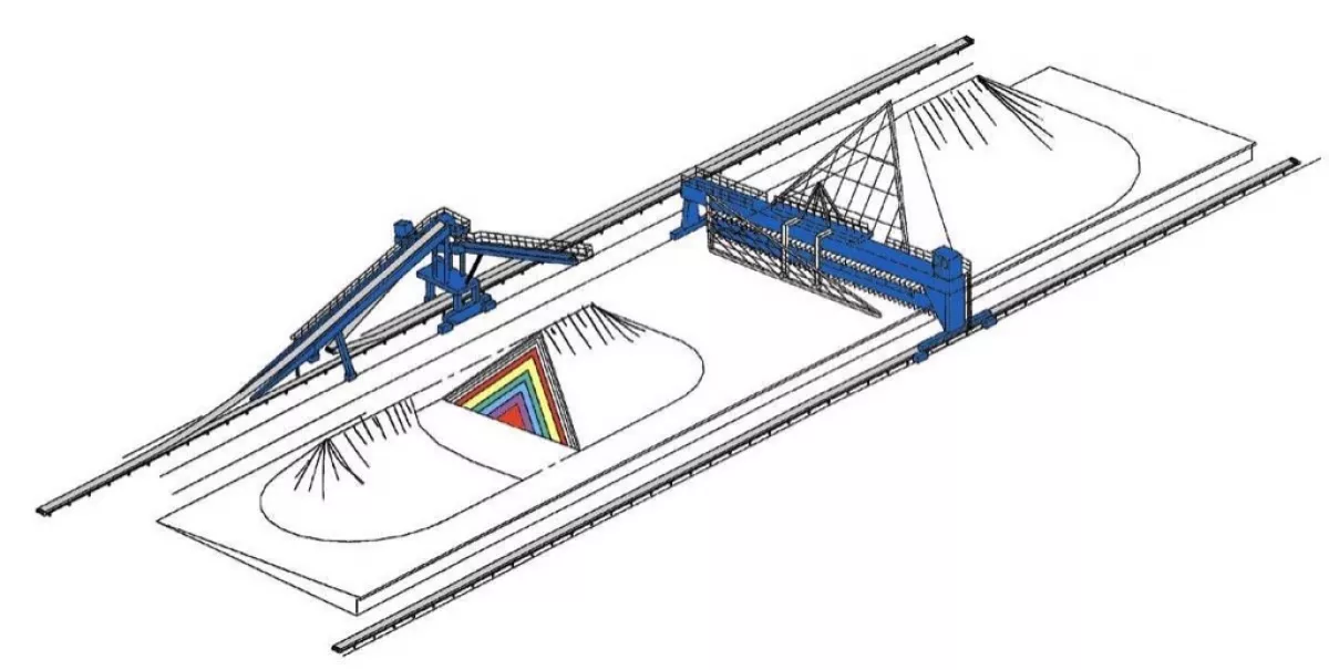
Linear Homogenisers (Dual Pile)
For a linear homogeniser, a complete pile is the quantity over which the homogenisation is achieved. If three days of production is the capacity of one pile, then three days is also the time span over which the variations will be smoothed out and equalised.
With a dual-pile operation however, a pile-end effect must be taken into account by which the homogeneity of the volumes of material stored in the extremities of a stack may not be as good as it is in the current section of the same, in particular under the adverse effects of segregation. This is mainly the case where piles are built in the chevron pattern but there is a stacking procedure to reduce this inconvenience.
Instead of stopping the stacker right above the cone centre, an additional travel distance is applied, shorter and shorter as the pile is growing, to follow the slope of the end cone. This method reduces the adverse pile end effect but requires more free space between the two stacks, which comes at the expense of storage capacity.
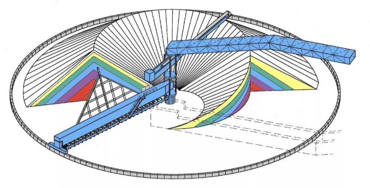
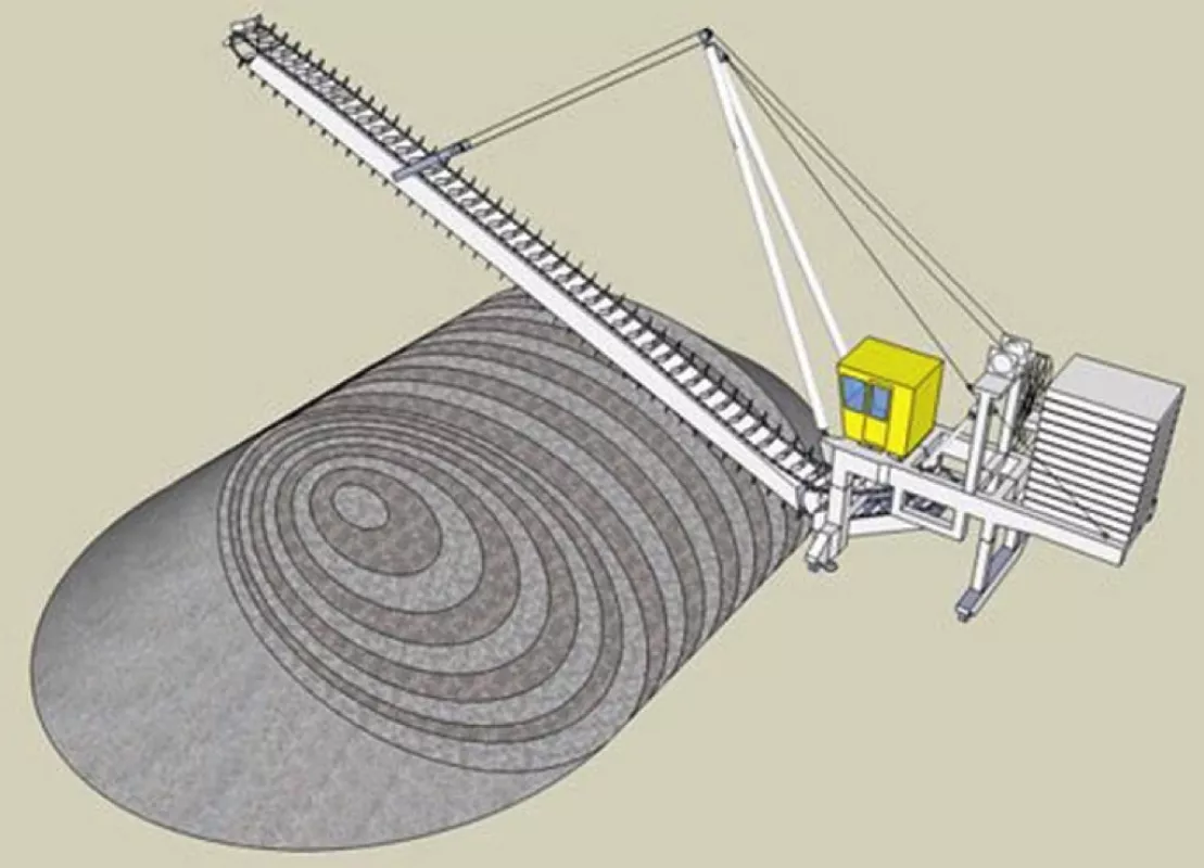
Circular Homogenisers (Continuous)
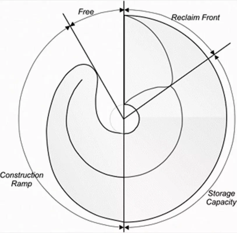
In circular blenders (continuous operation) there are no pile end effects. Homogenisation is carried out within the construction ramp itself. It is an early decision as to how much space is to be allocated to the ramp. The larger the ramp, the longer the homogenisation span and the better the homogenisation.
In practice, project specifications hardly ever impose any requirements on the homogenisation span. The only mentioned criterion is the sacrosanct blending ratio, which is commonly related to just the number of material layers. As a result, common practice sets the average ramp volume to one of the following criteria:
- Average slope of the ramp (standard ~20 degree),
- Sector angle filled by the ramp in the top view (standard 100 degree),
- Fraction of the storage capacity (standard ~30 percent).
Meaning of the Homogenisation Span
Apart from the adverse effect of segregation, it is a fact that almost all stockyard systems provide some homogenisation effect, in so far as the reclaiming flow never strictly follows the reverse order of the stacking flow.
During the reclamation process, the current output flow results from a combination of particles that have been deposited at various times during the stacking process. This will automatically provide some homogenisation.
However, when homogenisation performance is sought, the aim is to maximise the volume over which homogenisation is achieved and therefore maximise the age difference of all of the particles within a given output sample. The parameter to characterise this could be called the homogenisation span.
The meaning and importance of homogensation span can be better visualised on a continuous homogeniser.
The action of such is to produce an average number out of dispersed values. For a continuous homogeniser it is more about a moving average. Spent layers are disappearing at the bottom of the cross section while new ones appear at the top. The outflow results from the mix of all layers as cut by the raking system.
The following charts present a stochastic signal over a period of two and a half days. The first chart shows the rough signal. The second one shows the moving average made out of the signal at three hour, 12 hour and 24 hour spans respectively. It clearly appears that each moving average reduces the variations according to its span.
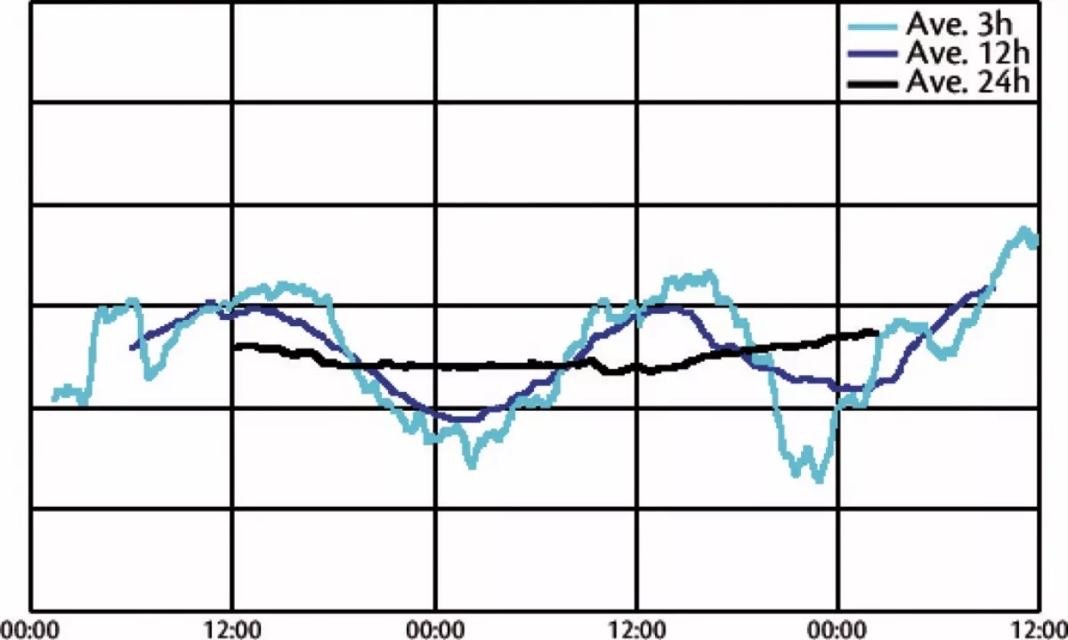
Defining the size of the ramp also defines the time over which the moving average will be assessed. The longer the time, the more stable the moving average. Ideally users should define a typical span through which they expect the variations to smooth out but this is likely to be an unknown. As a minimum, ramp sizes should be compared and equalised between different bidders.
Bulk Material Blending
Blending is a higher level function. It aims at obtaining not only homogeneity of properties over a given mass of compound product, but also to bring such properties as close as possible to a certain targeted level. Blending implies the knowledge of the inlet material flow properties plus the possibility of uniformly altering a mix by altering the proportion of each component of the inlet flow and the order in which they are stacked out.
Blending Performance
To reach blending performance, a good homogenisation must be achieved first. For this, a consistent homogenisation span must be defined. Blending requires something more, i.e. the capability to obtain a proportioned mix by controlled variations of the input flow.
To achieve this, an important feature is that all time periods of the stacking process are equally represented at any time in every bit of the outgoing flow. For example, if one corrective material must be added in a proportion as small as 1 percent of the total stack capacity, then it must be spread over the entire stack in a few layers that will each equally contribute to the outgoing flow. Such a feature defines a true blender compared to a mere homogeniser.
Number of Layers
Once the stockyard has been defined in terms of shape, size, stacking and reclaiming modes, it is time to consider the number of layers.
The number of layers results from the ratio between the stacking rate and the stacking speed compared to the cross section area of the pile. Obviously, a higher number of layers can only improve the quality of homogenisation and increasing the number of layers can be achieved by merely increasing the speed of the stacker.
Many theoretical analyses have been conducted into this matter to find the optimum conditions. The formula established by Pierre Gy and co-workers gives a blending efficiency equal to half the square root of the number of layers. This sets 400 as the number of layers necessary to reach a 1:10 ratio, which in most cases is a reasonable goal.
Care must be taken that increasing the speed of the stacker to achieve more than 400 layers may generate unnecessary costs because a limit is set by the size of the material itself. The blending will never be better than that allowed by the grain size.
Blending Monitoring
When a blender is linked to a continuous analyser (PGNNA type) installed on the incoming route, then it is possible to continuously adjust the proportion of each component in the blend so that the outgoing flow is on target at any given time.
SmartStack software has been developed with the goal of precisely controlling the incoming flow and preparing blends on the stack that are as close as possible to the target. To achieve this, a complete digital 3D map of the stack is constructed by a computer that controls the analyser (mound modelling). This allows for real time predictions of the future flow with regards to any quality control parameters or other requirements.
The characteristics of the input may be altered by the system either by control of the upstream route or information provided directly to the quarry management. Further developments can establish direct connections between the mound modelling software and the stacking control system to improve the optimisation of the blending operation. This may involve changing the rotation or travel speed of the stacker.
Stacking and Reclaiming Combinations
Table 1 examines the possible combinations of stacking patterns with reclaiming modes for both linear and circular stockyards. The most common matches are marked in bold letters.
| Linear | ||||
|---|---|---|---|---|
| Frontal | Side | |||
| Full-face | Pilgrim | Ladder | ||
| Cone shell | Inconsistent | Inconsistent | Inconsistent | Cost effective storage |
| Chevron | Good blending | Fair blending, beware of segregation | N/A | Cost effective single pile storage |
| Chevcon | N/A | N/A | N/A | N/A |
| Windrow | Excellent blending | Good blending | Good blending | Homogenisation |
| Circular | ||||
| Frontal | Side | |||
| Full-face | Pillgrim | |||
| Cone shell | Excellent homogenisation | Fair homogenisation, beware of segregation | Cost effective storage | |
| Chevron | Obsolete (dual pile) | N/A | Cost effective single pile storage | |
| Checron | Excellent blending | Fair blending, beware of segregation | N/A | |
| Windrow | N/A | N/A | N/A | |
Material Characteristics
Several key characteristics of the handled material must be taken in account. As there are no strictly identical commodities and no standard definition thereof, all records and experience with the real materials have to be taken into account wherever possible.
Bulk Density and Angle of Repose
These are the most important parameters in the determination of the size versus capacity of the stockyard and the size of most of the mechanical components. Only data recorded from existing stacks can give reliable data.
The angle of repose of a given commodity shall be regarded as depending on the 'age' of the stack. A fresh pile is rather unstable and slight disturbances trigger material slides. Day after day the angle of repose of the same stack is reduced by a few degrees.
Clients may state value ranges for the angle of repose as well as for bulk densities. The safe method consists in taking the higher value of the angle of repose for determining the maximum height of the stack and the related clearances of equipment, while considering the lower value of the same for determining the storage capacity. On the other hand, higher values of density are generally observed for stacked material due to pressure within the stack while lower values of the same are used for determining the size of the handling equipment, such as buckets, blades and conveyors.
Grain Size
Most of the materials handling equipment benefits from handling smaller sized grain. Smaller grains also help the blending performance of any type of blender. Large grains put higher stress on the machine parts, amplifies the risk of segregation and sets a limit to the homogenisation level.
It is difficult to set a standard for ideal grain size independently from the other parameters of the plant. In particular, the lower the reclaim rate, the smaller the handling devices such as reclaimer buckets. If an absolute limit to grain size was to be set it would not be above 150 millimetres.
Moisture Content
For a certain number of commodities, a high content of water may cause the flow properties of the bulk material to deteriorate. Some layered clay and chalk are likely to become difficult to handle with moisture content above 12 or 15 percent. For such materials, side reclaiming with self cleaning buckets equipped with scraping arms is recommended.
A Note from the Editor
For all statements in this article that refer – directly or indirectly – to the time of publication (for example “new”, “now”, “present”, but also expressions such as “patent pending”), please keep in mind that this article was originally published in 2012.
■

