

Replies
Used Silo Dosing & Loading Plant
Posted on
16. Aug. 2004 - 04:15
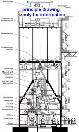
Photo 2:
Silo Plant general arrangement drawing
For more informatin, please contact:
Lantermann GmbH Industrieverwertung
info@Bergbaumaschinen.de
Germany
Attachments
■

Used Silo Dosing & Loading Plant
Ladies and Gentleman,
We are an internationally active consulting engineer with the emphasis on rebuilding industrial plants.
From this activity, we can offer a SILO- DOSING and LOADING- PLANT.
The plant is build in 1993 and in work until the end of 2004. Please contact us if you need more technical information and our price.
Specification of plant
1.1 Mixing Plant
1.1.1 Storage Silo
Capacity535, 5 m3 gross
Capacity500 m3 net
- Silo roof, pitch 3°, one-sided as pent- roofed
- Roof side rail
- Min/ Max. level indicator
- high/ low-pressure valve
- 1 unit manhole NW 800
- 1 unit air injection
- 1 unit run out
- slide valve as flat valve (motorist)
- ports for Silo- loosening
- 1 unit Silo- fill in equipment consisting of
• 1x5m spiral pressure tube
• 1 rigid coupling
• 1 blind coupling
• 1 crush valve DN 80
• 1 x45m flow pipeline DN 80
• 1 flow pipe bend DN 100, 90°
• 1 drop out pipe
1.1.2 Storage Silo
Capacity535, 5 m3 gross
Capacity500 m3 net
- Silo roof, pitch 3°, one-sided as pent- roofed
- Roof side rail
- Min/ Max. level indicator
- high/ low-pressure valve
- 1 unit manhole NW 800
- 1 unit air injection
- 1 unit run out
- slide valve as flat valve (motorist)
- ports for Silo- loosening
- 1 unit Silo- fill in equipment consisting of
• 1x5m spiral pressure tube
• 1 rigid coupling
• 1 blind coupling
• 1 crush valve DN 80
• 1 x45m flow pipeline DN 80
• 1 flow pipe bend DN 100, 90°
• 1 drop out pipe
1.1.3 Storage Silo
Capacity535, 5 m3 gross
Capacity500 m3 net
- Silo roof, pitch 3°, one-sided as pent- roofed
- Roof side rail
- Min/ Max. level indicator
- high/ low-pressure valve
- 1 unit manhole NW 800
- 1 unit air injection
- 1 unit run out
- slide valve as flat valve (motorist)
- ports for Silo- loosening
- 1 unit Silo- fill in equipment consisting of
• 1x5m spiral pressure tube
• 1 rigid coupling
• 1 blind coupling
• 1 crush valve DN 80
• 1 x45m flow pipeline DN 80
• 1 flow pipe bend DN 100, 90°
• 1 drop out pipe
1.1.4 Storage Silo
Capacity535, 5 m3 gross
Capacity500 m3 net
- Silo roof, pitch 3°, one-sided as pent- roofed
- Roof side rail
- Min/ Max. level indicator
- high/ low-pressure valve
- 1 unit manhole NW 800
- 1 unit air injection
- 1 unit run out
- slide valve as flat valve (motorist)
- ports for Silo- loosening
- 1 unit Silo- fill in equipment consisting of
• 1x5m spiral pressure tube
• 1 rigid coupling
• 1 blind coupling
• 1 crush valve DN 80
• 1 x45m flow pipeline DN 80
• 1 flow pipe bend DN 100, 90°
• 1 drop out pipe
1.1.5 Storage Additive
Capacity110, 8 m3 gross
Capacity100 m3 net
- Silo roof, pitch 3°, one-sided as pent- roofed
- Roof side rail
- Min/ Max. level indicator
- high/ low-pressure valve
- 1 unit manhole NW 800
- 1 unit air injection
- 1 unit run out
- slide valve as flat valve (motorist)
- ports for Silo- loosening
- 1 unit Silo- fill in equipment consisting of
• 1x5m spiral pressure tube
• 1 rigid coupling
• 1 blind coupling
• 1 crush valve DN 80
• 1 x45m flow pipeline DN 80
• 1 flow pipe bend DN 100, 90°
• 1 drop out pipe
1.1.6 Silo- Loosening
- 1 unit Silo- Loosening consisting of
• Ring pipe with powered ring butterfly valve
• Ring butterfly valve
• Non return valves
• Hand butterfly valves
A shared compressor is integrated, to get a permanent discharge out of Silo, and to avoid compression of material
1.1.7 Silo- Loosening
- 1 unit Silo- Loosening consisting of
• Ring pipe with powered Ring butterfly valve
• Ring butterfly valve
• Non return valves
• Hand butterfly valves
A shared compressor is integrated, to get a permanent discharge out of Silo, and to avoid compression of material
1.1.8 Silo- Loosening
- 1 unit Silo- Loosening consisting of
• Ring pipe with powered Ring butterfly valve
• Ring butterfly valve
• Non return valves
• Hand butterfly valves
A shared compressor is integrated, to get a permanent discharge out of Silo, and to avoid compression of material
1.1.9 Silo- Loosening
- 1 unit Silo- Loosening consisting of
• Ring pipe with powered Ring butterfly valve
• Ring butterfly valve
• Non return valves
o Hand butterfly valves
A shared compressor is integrated, to get a permanent discharge out of Silo, and to avoid compression of material.
1.1.10 Silo- Loosening
- 1 unit Silo- Loosening consisting of
• Ring pipe with powered Ring butterfly valve
• Ring butterfly valve
• Non return valves
• Hand butterfly valves
A shared compressor is integrated, to get a permanent discharge out of Silo, and to avoid compression of material.
These Loosening components are adapted to the reduced requirements of the Additive- Silos
1.2 Recycling material conveyance and dosing
1.2.1 Conveying system
Consisting of
- 1 unit haul off and dosing screw with
• armoured spiral screw
• slurry thickener powered by transmission
• out laying bearing
• frequency controlled drive
• weighted cap at screw dropping
• hand hole cap at dropping spike
1.2.2 Conveying system
Consisting of
- 1 unit haul off and dosing screw with
• armoured spiral screw
• slurry thickener powered by transmission
• out laying bearing
• frequency controlled drive
• weighted cap at screw dropping
• hand hole cap at dropping spike
1.2.3 Conveying system
Consisting of
- 1 unit haul off and dosing screw with
• armoured spiral screw
• slurry thickener powered by transmission
• out laying bearing
• frequency controlled drive
• weighted cap at screw dropping
• hand hole cap at dropping spike
1.2.4 Conveying system
Consisting of
- 1 unit haul off and dosing screw with
• armoured spiral screw
• slurry thickener powered by transmission
• out laying bearing
• frequency controlled drive
• weighted cap at screw dropping
• hand hole cap at dropping spike
1.2.5 Conveying system
Consisting of
- 1 unit haul off and dosing screw with
• armoured spiral screw
• slurry thickener powered by transmission
• out laying bearing
• frequency controlled drive
• weighted cap at screw dropping
• hand hole cap at dropping spike
1.2.6 pour flow instrument
To check and control the material flow with haul off and dosing screw by a default valve, consisting of:
- 1 unit pour flow instrument with
• integrated force sensor
• defector
• deflector box in steel material
1.2.7 pour flow instrument
To check and control the material flow with haul off and dosing screw by a default valve, consisting of:
- 1 unit pour flow instrument with
• integrated force sensor
• defector
• deflector box in steel material
1.2.8 pour flow instrument
To check and control the material flow with haul off and dosing screw by a default valve, consisting of:
- 1 unit pour flow instrument with
• integrated force sensor
• defector
• deflector box in steel material
1.2.9 pour flow instrument
To check and control the material flow with haul off and dosing screw by a default valve, consisting of:
- 1 unit pour flow instrument with
• integrated force sensor
• defector
• deflector box in steel material
1.2.10 pour flow instrument
To check and control the material flow with haul off and dosing screw by a default valve, consisting of:
- 1 unit pour flow instrument with
• integrated force sensor
• defector
• deflector box in steel material
1.3 Recycling material- mixing- und loading plant
1.3.1 1 unit one axle pass mixer
For continuous mixing of Silo- ingredients with water, consisting of
- mixer hitch in steel, particulate lined with plastics
- mixer axle with 120° mixer series
- mixer drive incl. gear und coupling
- conveying cab at infeed
- infeed600x 1000mm
- outlet600x 1000mm
alternative
1.3.2 1 unit double axle mixer
For continuous mixing of Silo- ingredients with water, consisting of
- mixer hitch in steel
- 2 unit mixer axle with adjustable mixer wings
- mixer wing with carbide- side reinforcement
- mixer drive incl. gear und coupling
- conveying cab with integrated water sprinkling
1.3.3 1 unit water mixing system,
Consisting of
- 1 unit water supply tank on ground floor with
• level control
• tank cap
• pipe connection
• inside mothballing with Inertol-Poxitar, 40 µm
- 1 unit pressure increase system with
• rotary pump with frequent controlled drive
• suction pipe DN 100, mounted
• pressure pipe
- 1 unit control system
To check water flow rate, consisting of:
• pressure reducer
• water filter
• inductive flow control
• automatic quality adjusting by pump speed
• hand shut-off devices
• optical pressure gage
• pipe for control equipment
1.3.4 funnel for finished material as surge tank
Build cylindrical with bent down conic expansion
Volume 50m3
1.3.4Silo discharge system
ClearanceØ 1000mm
Height1000mm
Device as welded construction with engine for rotation ream sickle
1.4 dedusting
1.4.1 1 Unit bunker filter cap
Mounted on top of Silo 1.1.1
Build with mechanical cleaning, welded construction
Dust source:pneumatically filled Silos 1.1.1, 1.1.2, 1.1.3, 1.1.4
Including electrical control of cleaning system
Clearing range controlled electrical
1.4.2 1 Unit bunker filter cap
Build with mechanical cleaning, welded construction
Dust source:Additivsilo 1.1.5
Including electrical control of cleaning system
Clearing range controlled electrical
Dedusting ventilator
Steel panel box with lateral mounted bracket for engine, balanced impeller in an overhang position on engine axle
Pipeline
Build in welded steel panel, compl. With screws seals flange adapter fittings etc.
1.5 electro- technics
1.5.1 region E- technics
1 Unit switchboard plant consisting of:
-Power stack for electrical drives
-Switchboard, steel panel, protection class IP 54
-induct field for U= 400V with power switch, conductor rail switch, ampere meter, volt meter, volt meter switch
-power stack for electrical drives with motor contactor, motor drive until 4kW with motor protection switch and group protection, motor drive above 4 kW with Bi- metal relay and protection circuit breaker
-Remote control cabinet for 5 metering units
Consisting of, for each metering unit
• microprocessor, weighing system, keyboard,
• numeric display:
- power to/h
- power %
- defector load %
- flow regulator %
• control panel
• power electronics for frequent modulated drive of dosing screws, incl. control
1.5.2 control technology – control system
1 Unit switch board consisting of:
-Compl. Control technology with integrated display and keyboard. Controls build as a RAM programmable controller system SIMATIC S5, 135 U compl with central processing unit, I/O- port and power supply unit.
Control system with own control and signal powering transformer, protection with circuit breaker. 220V circuit with earth leakage protection.
The 24V circuit has to be earth on secondary side. Safety message like overcurrent, linkage emergency switch, slope run has to be wired directly over contactor with the 220V motor control circuit. Additionally these messages are proved as a accumulated disturbance
Displays in coloured screen-print.
Process Symbolic representation
Each drive and each silo fill level are displayed as a operative message witch
Constant flash in process or flash in operation fault.
Faults additional signalled acoustically
Local measuring
• 1 Silo pilot for continues level monitoring
• 1 max. safety probe in each silo
• all local pressure measuring incl. shut off valve
• level
• plenty
• manometer
• level control
• plenty control
• all needed extraction fitting and dive bushing for test- and discharging measuring
Analog measuring
• all needed measuring and control circuit for water flow control and material flow control incl. visual indicator
Other equipment
• all needed speed sensing, linkage emergency switch, slope run control , cam switch, I/O port , emergency stop, alert horn, light signal, truck loading etc.
For more informatin, please contact:
Lantermann GmbH Industrieverwertung
href="mailto:info@Bergbaumaschinen.de">info@Bergbaumaschinen.de
Germany
Photo 1:
Silo Plant
Attachments
lantermann_silo_news1e (JPG)
■