
Countries with high rate of economic growth like China, Brazil, Russia are constantly upgrading their port infrastructure to meet increasing demand for import and export of various bulk materials. Tandem wagon tipplers have been employed extensively to achieve higher unloading rates and improve the utilisation of existing railway infrastructure.
In China at the Huanghua coal export terminal six tandem rotary tipplers supplied by ThyssenKrupp have been installed to achieve export figures of 80 million tons of coal per year. Each tippler at this port simultaneously unloads two rail freight box type wagons, with a payload of 60 to 70 tons each, at a rate of up to 33 cycles per hour, thus unloading an average 4000 tons of coal per hour with a maximum capacity of 4500 tons per hour.
At the port of Tubarao in Brazil, five tandem tipplers supplied by ThyssenKrupp are in operation - each having a handling capacity of two 120 ton (gross weight) wagons with rotary coupler at 45 dumping tips per hour of iron ore.
Similarly at Ust Luga, one of the largest ports in Russia, two tandem tipplers are installed to unload coal at the rate of 3500 tons/hour each for export of Russian coal.
1. Indian Scenario
In India, as per old railway guidelines (RDSO - Research Design and Standards Organisation), the dumping capacity of tipplers was limited to not more than 20 tips/hour. Hence side discharge tipplers having a maximum of 20 tips per hour were popularly used to unload material from railway wagons of 110 tons gross weight in ports, power, steel and cement plants. Rotary tipplers have been less popular in India in the past, as it calls for four to five meters deeper underground civil construction than side discharge tipplers. Especially for small scale projects, civil construction costs grew to a considerable percentage of total project cost.
The energy requirements of side discharge tipplers are much higher due to the lift and shift type operation while unloading the box wagon. They require heavy counterweights to even out the mechanical effort. In contrast, rotary tipplers are energy efficient as they rotate the wagon about its center of gravity. No counterweights are necessary in this case.
Side discharge tippler design is not suitable for more than 27 to 28 tips per hour and also is not amenable to tipple more than one wagon at a time.
As per the new RDSO guidelines effective from December 1, 2010, the number of tips has been increased to more than 25 tips per hour for both side discharge and rotary tipplers to achieve higher unloading capacity and more turnarounds of rakes per year. These new guidelines now also permit the use of single as well as tandem wagon tipplers.
Indian economy is growing at a rapid pace creating a high demand for raw materials by steel, cement and power plants. It is necessary, therefore, to improve the utilization of the available railstock and railway network as it is the main source of transport for bulk materials. Thus necessity is felt to introduce high capacity tandem tipplers in India.
Today new steel, power and cement plants are being set up in India and the capacity of existing plants is being expanded. In a steel plant we need to unload approx. 3 tons of raw materials like coal, iron ore, dolomite, limestone etc. for producing one ton of steel. Since all the above raw materials are transported by railway wagons, the tandem tippler is an ideal solution to unload rakes at the high rate of more than 3500 tons per hour making effective use of limited railstock, smaller rail yard area and limited rail lines connecting to the main railway network.
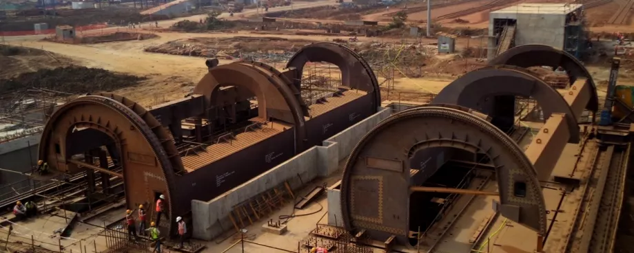
This is a special constraint for landlocked steel plants which want to expand the steel production. For their new three million ton steel plant project at Kalinganagar, Odisha, Tata Steel have incorporated two tandem and two single C-type rotary tipplers in the scheme to unload about nine million tons of the above mentioned raw materials. This will be the first installation of tandem tipplers in India.
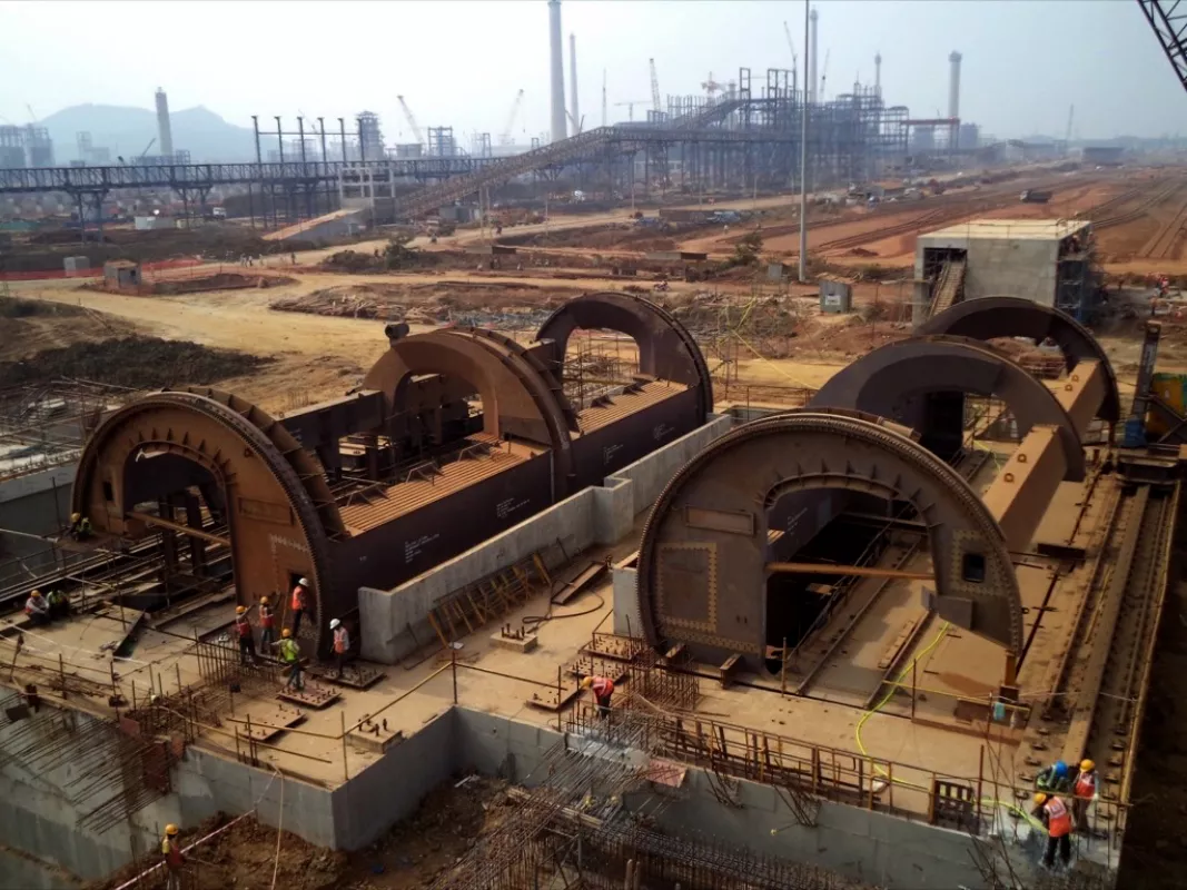
The new tandem tipplers will unload two 140 ton (gross weight) wagons at a time at the rate of 25 tips per hour. The supplied tipplers are designed as per the latest RDSO guidelines and can tipple all types of existing box type wagons as well as the proposed DFC and feeder route wagons, to be introduced in the near future for coal and iron ore transportation.
For a bulk export terminal, where we have to load ships in the minimum possible time, tandem tipplers can play a pivotal role for unloading trains carrying coal, iron ore etc. at higher rates and make effective use of limited railstock, smaller rail yard area and limited rail lines connecting to main railway network.
Recent trend of installing mega and ultra mega power plants, has increased daily coal requirement of power plants substantially. For a 4000 MW power plant, the typical coal requirement may be up to 40 000 or 45 000 tons per day. To cater for such high requirements, again rotary tandem tipplers will satisfy this requirement by unloading at rates of approx. 3500 to 5000 tons per hour in eight to twelve hours. One can achieve a capacity between 10 and 15 million tons per year with a single rotary C-frame type tandem tippler.
2. Tandem Tippler Installation and Operation
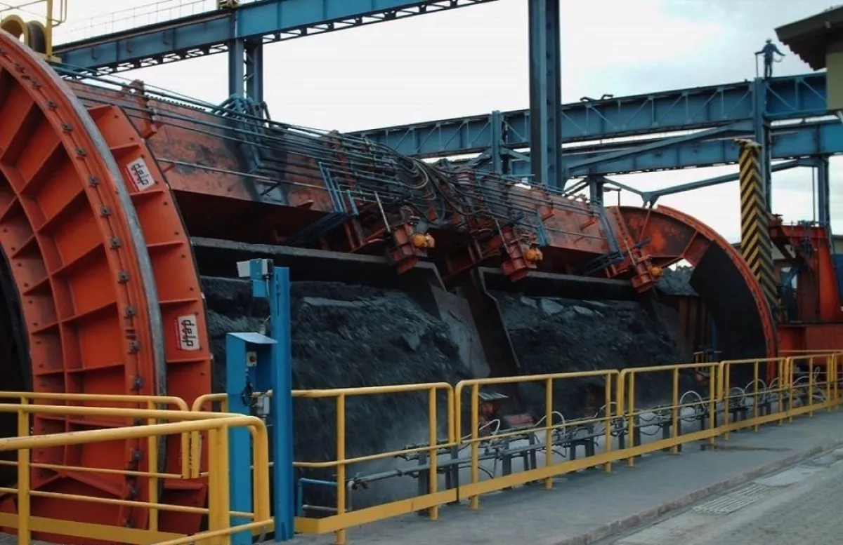
There are two types of tandem rotary tipplers: ”O”-type and “C”-type tipplers.
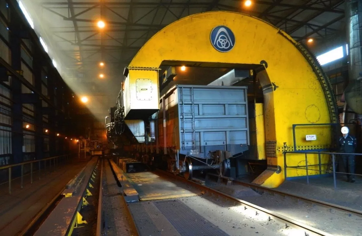
The C-type tandem tipplers are more popular nowadays due to its C-shaped frame - open at one side which allows side arm charger to travel through the tippler and place loaded wagons on the tippler platform while pushing empty wagons out of the platform where they help to form the empty rake on outhaul side.
O-type tipplers are more popular in the countries where railstock is provided with rotary coupling – here it is not necessary to decouple the wagons during tippling. These tipplers can achieve very high tippling cycles of up to 45 tips per hour. Wagon placement on O-type tipplers is done using rope driven side arm chargers.
As rotary couplings on wagons do not require de-coupling higher tip rates are feasible. This advantage can be derived only in rotary tipplers. Wagons with rotary couplers, however, are not actually not utilized in India. Hence the O-type tippler is not popular.
The tippler is controlled by PLC system in either manual or fully automatic mode. The drives for tippler are either variable speed controlled electro-mechanical drives or hydraulic drives.
In case of a hydraulic drive, the hydraulic power pack can be kept away from the dusty environment in a separate closed pressurized room. Electric panels of VVFD drives are protected from dusty environment by placing them in a separate airconditioned room.
Variable speed controlled electric drives are advanced and effectively used with regenerative braking for both tippler and side arm charger - with consequent reduced demand on the power network. This regenerative feature is not available with hydraulic drives.
In a mobile machine like side arm charger, indexer and puller cum pusher of transfer platform, it is recommended to provide electro-mechanical drives with VVVF control. We can place the VVVF panel in a separate closed pressurized dustfree room inside the control tower, and the power is supplied to the drive motors through flexible cables using an energy drag chain or a festooning arrangement. Such an arrangement is not possible with hydraulic drives.

