
(From the archive of ”bulk solids handling", article published in Vol. 32 (2012) No. 4 , ©2012 bulk-online.com)In Australia the status quo of coal in bottom dump wagons and iron ore in rotary dump gondola cars seems to be entrenched. However the reverse has also been the practice and as the trend is to increase the capacity of loading and unloading and in particular to consider lower capital cost for unloading unit trains it is necessary to review the state of the art. This article reviews current practice and suggests that bottom dump hopper wagons are more efficient particularly for increasing the unloading rate of unit trains.
Introduction
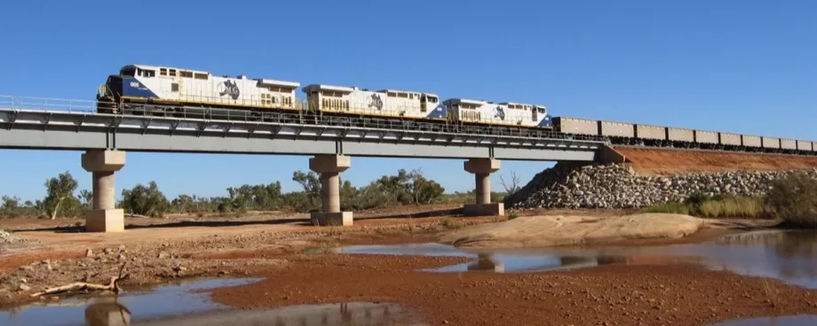
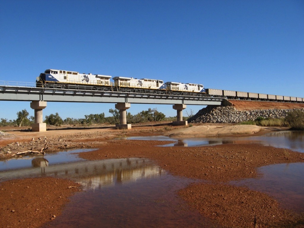
The unit train is loaded with one product at similar loading stations and is unloaded at the same receival station and hence they are more efficient than mixed trains and road transport particularly for large consignments and long travel distance. In the train all the wagons are identical and usually carry bulk goods: iron ore, coal, bauxite or wheat, for example.The wagons are top loaded by gravity from a clam gate under a hopper which is under a bin or stockpile and the train moves slowly under the gate. The material is delivered to the bin or stockpile by a belt conveyor and the locomotives are not disconnected.Depending on the design of the wagon, e.g. a gondola car or bottom dump wagon, the train is unloaded by rotating the car and tipping the contents out or the bottom doors of the hopper wagon are opened and discharge is by gravity. For unloading the bottom dump wagons the train travels slowly over the receival hopper and the locomotives are not discontented.By contrast the unloading of rotary dump cars requires a complex procedure and expensive auxiliary equipment to carry out this procedure. The unit train on arrival at the dump station must be broken up into manageable length rakes, this requires marshalling yards and shunting locos.Each dumping rake needs to have the first wagons located accurately into the dump rotary device and locked in position. In addition, indexing equipment is engaged to the dump rake, the indexer operates a cycle to push the wagons into position and return for the next cycle, the indexing cycle is married to the dumping cycle.For both unloading methods the material is collected into a receiving hopper with a feeder to deliver the material in a controlled manner onto a belt conveyor.In the coal industry a typical train is capable of travelling under the loading gate at 1.2 kilometres per hour and receives coal at between 6000 and 6500 tonnes per hour. For iron ore the train speed is 0.9 kilometres per hour and receives iron ore at between 11,000 and 11,500 tonnes per hour. The rate is dependent on the gravity discharge rate of the loading bin or stockpileFor gondola cars the discharge rate depends on the payload in the car and the dump cycle. A typical two rotary car dumper can discharge iron ore at the nominal rate of 8000 to 11,200 tonnes per hour. For hopper wagons the discharge rate depends on the design of the hopper and the flowability properties of the bulk material.
Coal and Iron Ore Flowability
Flowability test work, see [1,2], is required for all the material that is to be loaded and unloaded into and from a unit train. It is required to determine the design parameters for a mass flow conical loading bin, the design of the loading gate, the suitability of a bottom dump hopper car, the design of the dump station recieval hopper and its interface with and design of the belt or apron feeder.
| Bulk material | Coal | Iron ore |
| Bulk density [t/m3] | 0.7 | 2.1 |
| Internal friction angle δ [°] | 50 | 60 |
| Wall friction angle ϕ [°] | 45 | 55 |
| Cohesion [kPa] | 2 | 5 |
| Effective yield locus | 0.2 | 0.4 |
Typical results for coal and iron ore are shown in Table 1. These parameters are used to determine the following properties:
- the half angle of the mass flow hopper,
- the lining material (the popular choices for liner material is stainless steel for coal and dua-plate tiles for iron ore DSO products, i.e. lumpy and fines),
- the maximum free discharge rate from the bin for a given outlet diameter,
- the outlet diameter (the gates fitted to the outlet may influence this flow rate depending on the gate design),
- the geometry of bottom dump hopper wagons,
- the dump station receival hopper,
- the receival hopper feeder loads, and
- the transfer chute from feeder to conveyor belt.
Loading Bins and Stockpiles
In general unit trains are loaded from ground stockpiles, the stockpile may be reclaimed by a bucket wheel reclaimer [7,8] and conveyed to a load out bin located over the tracks, and in the other the stockpile is accessed by a tunnel and the train loaded by gravity flow. The wagon loading gates, mass flow hopper, and expanded bin is common to both concepts. The choice between either system is based on costs on the one hand the bucket wheel reclaimer, conveyor and loadout bin designed for the train loading rate required and on the other the cost of a train tunnel under the stockpile and achieving the the same train loading rate. As the requirement for train loading rates increase the cost of the reclaimer based system becomes more expensive and the tunnel reclaim system becomes more economic.The typical mass flow conical bin used for train loading for iron ore and coal is shown in [7]. Its design geometry is based on flowability test work described above. The same testwork will determine the design geometry for a stockpile gravity system [4].The volumetric capacity of the bin is approx. 1000 cubic metre with the train consignment to be reclaimed by the bucket wheel reclaimer. The bin acts as a surge buffer between the reclaimer and the wagons. The gravity flow stockpile needs to be sized to hold the total train consignment and may require very large conical stockpiles and/or multiple gates on longitudinal stockpiles.
Loading Gates and Chutes
These are typically clam shell or tunnel gates fitted under the mass flow hopper of a circular bin or stockpile.The tunnel gate requires that the wagon is spotted into position before the tunnel gate is lowered [4]. The initial instantaneous flow rate into the wagon has been observed in the order of 90,000 tonnes per hour when the chute was raised additional tonnes discharge into the wagon. This type of system built in 1969 is very difficult to control, gross tonnes being excessive and the centre of gravity of burden in the wagon off centre. Axle loads often exceed permissible load with consequent damage to the track leading to high maintenance on wheels and track particularly in curvesIn the mid 1970’s a prototype chute was developed to load the cars more evenly and on a continuous basis eliminating the requirement for the wagons to be spotted [4]. The concept was to fit a clam gate to the existing tunnel gate which would open and close as the wagons passed under at a slow speed. The primary benefit was to load the payload in the wagons more evenly and avoid excessive axle loads. The project was abandoned before insitu trials could assess performance.Another solution is the telescopic chute, which usually used in coal industry under a circular bin and is reported to be very successful. The telescopic chute is designed to minimise dust during loading.In 1988 a different type of telescopic chute was installed for loading iron ore under a gravity flow stockpile, three gates in total were installed. The application was reported as erratic depending on the flowability of the ore. When the iron ore was relatively dry there was excessive flow rates and aeration. The train loadout tunnel was subject to bogouts and major delays occurred to clear out the tunnel resulting in reduce overall loading rates. When the iron ore was wet the flow rates were reported to be slow and train loading times exceeded schedule requirements.In 1994 a concept, similar the prototype chute developed in the 1970's, was installed to load iron ore. In this case the gate was installed under a circular mass flow bin and the feed was from a bucket wheel reclaimer. The iron ore was DSO product lumpy (-32+6 millimetre) and fines (-6+0 millimetre).In 1997 the concept was reported to require high maintenance handling lump ore and subject to hang ups when handling fines causing serious delays in loading 200 wagon trains.At about same time at another iron ore mine similar loadout gates were installed under a conical stockpile with tunnel access for loading trains. In this case the iron ore was 6+0 millimetre and free flowing. It was reported that 300 wagon trains were being consistently loaded at train speeds of 1.4 kilometres per hour.Since this time this type of load out gate is preferred with a circular bin fed by bucket wheel reclaimers. However in these cases the train loading speed was reported to be in the 0.7 to 0.9 kilometre per hour range due to the limitation of the reclaimer capacity. Larger reclaimers have been considered and installed but to date train loading speeds have not been reported.
Hopper Wagons and Gondola Cars
The 120-tonne coal wagon payload is 97 tonnes. The wagon, manufactured in stainless steel, is top loaded and discharged through eight transverse doors, and designed to ensure that the wagon is totally discharged while travelling at 1.2 kilometres per hour for a wide range of coal properties. Details of the type of wagon can be found in [3].The HTA 102-tonne bogie hopper wagon was introduced by the UK rail freight company EWS and has been specifically designed for carrying coal with a 75-tonne payload. The wagon is top loaded by gravity discharge through three clam gate doors, longitudinally arranged and pneumatically operated [7].The GML (Goldsworthy Mining Associates) iron ore bottom dump hopper wagon operated at the first iron ore mine opened in the Pilbara. The first shipment despatched June 1, 1966. The distance railed was 100 kilometres and it carried primary crushed iron ore. The wagons were top loaded and had two longitudinal clam gates. The line was extended to the Yarrie mine about 200 kilometres from Port Hedland.The typical gondola car was introduced at the second iron ore mine in the Pilbara. The wagons were coupled in pairs and discharged in a rotary dumper in Dampier. The iron ore was railed as DSO products, lumps and fines [4].Other mines operate individually rotary wagons and hence may be dumped in single, twin and triple wagon rotary dumpers. The triple wagon dumper may achieve discharge rates from 9000 to 12,600 tonnes per hour.
Dump Stations and Dump Hopper Feeders
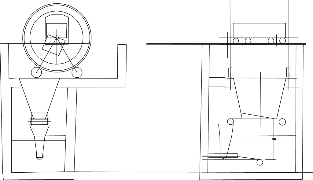
The typical receival station for iron ore and coal consists of a recieval hopper with feeders which delivers to a belt conveyor system. They differ only in the unloading concept of the wagons. A typical layout for a bottom dump station and for rotary dump station is shown in Figs. 2 and 3 respectively.The obvious difference between the two concepts is the increase depth of construction, all other heights being equal, recieval hopper, feeder and transfer chute to belt conveyor. Not shown is the indexer car pusher for the rotary dumper which requires additional real estate and construction facilities.Dump hopper feeders are generally equipped with either belt or apron feeders. The basic structure of a dump hopper feeder with belt feeder is illustrated in Fig. 2.
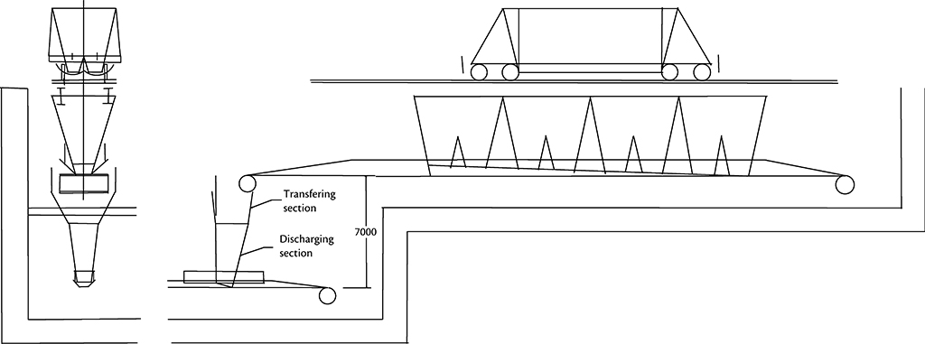
Parameters of a belt feeder at unloading rates typically reported in practice can be found in Table 2. The length of the belt feeder used for Table 2 is is 36.4 metres, the hopper length 23.5 metres.
| Bulk material | Belt feeder coal | Apron feeder iron ore |
| Capacity [t/h] | 7212 | 2 × 5074 |
| Speed [m/s] | 0.9 | 0.22 |
| Power [kW] | 597 | 2 × 199 |
| Installed power [kW] | 630 | 2 × 250 |
| Width [mm] | 3000 | 2400 |
| Belt/chain rating | St 2500 | D9L |
| Pulley/sprocket diameter [mm] | 1500 | 991 |
Fig. 3 illustrates the basic structure of a dump hopper feeder with an apron feeder. The parameters of such an apron feeder at unloading rates typically reported in practice can also be found in Table 2. here, the feeder length is 11 metres and the hopper length 7 metres.
Loading and Discharge Rates
The Tables 2 to 6 are determined using the flow properties given in Table 1. Table 3 shows the discharge rate from the mass flow hopper which may be under a circular bin or under a gravity discharge stockpile. It is the upper most limit of the loading rate of a unit train. Table 4 shows the loading rate of a unit train based on the constant speed of the train as it travels under a loading chute.
| Bulk material | Coal | Iron ore |
| Hopper half angle [°] | 22.5 | 15.0 |
| Lining material | Stainless steel | Dua plate |
| Outlet opening diameter [m] | 1.5 | 1.5 |
| Max. discharge rate [t/h] | 20000 | 80000 |
| Bulk material | Coal | Iron ore |
| Wagon payload [t] | 22.5 | 15.0 |
| Permissible axle load [t] | Stainless steel | Dua plate |
| Average loading rate [t/H] | 1.5 | 1.5 |
The discharge rate from a mass flow hopper wagon is shown in Table 5. It is the upper most limit of the hopper wagon unloading rate. Table 6 shows the unloading rate of a unit train with bottom dump hopper wagons based on a constant travel speed of the train as it travels over a receival hopper.
| Bulk material | Coal | Iron ore |
| Slot opening [m] | 0.7 | 0.7 |
| Slot length [m] | >2.5 | >2.5 |
| Lining material | Stainless steel | Dual plate |
| Hopper half angle [°] | 30 | 22.5 |
| Discharge rate/slot length [t/h/m] | 5000 | 20000 |
| Bulk material | Coal | Iron ore |
| Average unloading rate [t/h] | 12020 | 16914 |
| Discharge time [t/s] | 4 | 5 |
| Time to empty [s] | 25 | 30 |
| Travel distance [m] | 8 | 10 |
Table 2 shows the typical parameters of the receival hopper feeders at the unloading rates typically reported in practice. For coal the train would be travelling at 0.6 kilometres per hour. For iron ore the dumper would be a twin car system with 120 tonne payload, see Table 7, which shows the discharge capacity with regards to payload cycle time and number of cells.
| Type | No. of cells | Cycle time [s] | Payload/wagon [t] | Discharge rate [t/h] |
| Single cell | 1 | 1 | 100 | 6000 |
| 120 | 7200 | |||
| 140 | 8400 | |||
| Twin cell | 2 | 1.5 | 100 | 8000 |
| 120 | 9600 | |||
| 140 | 11200 | |||
| Triple cell | 3 | 2 | 100 | 9000 |
| 120 | 10800 | |||
| 140 | 12600 |
Discussion of Unit Train Wagons
For iron ore, a typical twin rotary car dumper can discharge a train between 8000 to 11,200 tonnes per hour depending on the payload in the cars, cycle time and number of cars dumped, see Table 7. An iron ore unit train with bottom dump hopper wagons travelling at 1.2 kilometres per hour has the potential to discharge at the rate of 7500 to 10,148 tonnes per hour depending opening width and length.The production rates are comparable and any advantage between rotary dump and bottom dump unit trains need to consider other factors. Such factors would include capital cost of dump station, reduced equipment operations and maintenance, reduced marshalling yard requirements, less impact on rail operations to break unit train into smaller rakesThe bottom dump wagons are more expensive, have a higher tare weight, require more maintenance, and have a higher hang up risk. Gondola rotary dump cars have been observed to hang up occasionally. For an equal number of wagons in the train the track gradients and locomotive performance need to be considered. Conversely for a given track profile and locomotive fleet the number of wagons and hence total train payload will be restricted. As iron ore trains became longer, catastrophic failure of the draw bar increased. One iron ore operator has reported a 50 percent reduction in train separation issues in 2011 over a previous 3 year period.
Discussion of Receival Hopper Feeders
When considering the type of feeder the overall height for the receival hopper, feeder, and transfer chute to receiving conveyor is similar if not identical (Figs. 2 and 3). Therefore the choice of a belt feeder or apron feeder is to decide which is most capable to handle the material, in this case coal and iron ore.The definitive test is the ability for each to operate efficiently against the pull loads exerted by a full receival hopper. The belt feeder has to avoid traction slippage at the drive pulley particularly under starting conditions. A technical study will identify the limitations of both and estimate the cost of each. Belt selection will depend on the Factor of Safety issues and for Apron feeders these also have the issue of chain safety factor against the breaking load of the chain.Experience shows that for iron ore the apron feeder is the preferred choice. In coal the belt feeder can be used but its limitations must be known. The hopper loads must be determined and failure to do so will affect the starting requirements.For example in the Fig. 2 the hopper is fitted with a number of witches hats to reduce belt loads, removal of the intermediary hats will prevent the feeder from starting with a full hopper. Conversely if belt loads are not considered then critical insitu modifications will be required.It should be noted that as train speeds are increased the length of the receival hopper has to be made longer to receive the coal discharging from the hopper car and hence longer belt feeders would be required.The same is true of apron feeders which can take much higher chain/sprocket loads but it has its limits and therefore two apron feeders are usually required, effectively introducing a large witches hat division in the receival hopper, see Fig. 3 for a two-car dumper.However the lower allowable belt pull loads restrict capacity and will restrict train unloading speeds. For coal the feeder will restrict train unloading speeds down to 0.6 kilometres per hour, see Table 2. For higher trains speeds an apron feeder should be considered.
Conclusion
For iron ore when considering unloading rates greater than 15,000 tonnes per hour the concept of unit trains with bottom dump wagons may have a lower capital cost, less maintenance of fixed plant infrastructure and more efficient train operations. However, these advantages may be offset by increased rolling stock maintenance.For coal when considering unloading rates greater than 15,000 tonnes per hour then apron feeders under the receival hopper particularly as longer receival hoppers will be required for faster train speeds. Perhaps where belt feeders are installed it would be prudent to consider the feasibility of replacing with apron feeders. Need to establish if there is a net benefit to justify the cost.A train unloading rate greater 15,000 tonnes per hour is necessary if direct train to ship loading is being considered. E.g. 10 × 200 car unit trains, total consignment of 240,000 t which would load a vessel in 16 hours assuming that delays between trains is minimised, the vessel would depart on the second high tide.
A Note from the Editor
For all statements in this article that refer – directly or indirectly – to the time of publication (for example “new”, “now”, “present”, but also expressions such as “patent pending”), please keep in mind that this article was originally published in 2012.
References:
- Jenike, A.W.: Storage and flow of solids. Bulletin 123, University of Utah, Salt Lake City, 1964.
- Arnold, P.C., McClean, A.G., Roberts, A.W.: Bulk solids storage, flow and handling. University of Newcastle Research Associates (TUNRA) Ltd Australia. 1992.
- Craig, D.A., Wiche, S.J., Chambers, A.J.: Materialshandlingdesign considerations for 120 t coal wagon. Mechanical Engineering Transactions Vol. ME22 No 1 & 2 1997.
- Maton, A.E.: Gravity storage and discharge systems for loading unit trains. bulk solids handling Vol. 18 (1998) No. 1.
- Roberts, A.W., Wiche, S.J.: Interrelation between feed chute, geometry and conveyor wear. bulk solids handling Vol. 19 (1999) No. 1.
- Maton, A.E.: Design review of conical stockpiles comparing mass flow hoppers and vibrating dischargers. bulk solids handling Vol. 20 (2000) No. 3.
- Maton, A.E.: Unit train loading systems – rail wagon loading times. bulk solids handling Vol. 24 (2004) No. 2.
- Maton, A.E.: Unit train loading systems – reclaimer selection and wagon weighing. bulk solids handling Vol. 24 (2004) No. 3.
| About the Author | |
| Albert E. MatonOwner & Managing DirectorMaton Engineering, Australia |
■

