
(From the archive of ”bulk solids handling", article published in Vol. 32 (2012) No. 5 , ©2012 bulk-online.com)Opencast mines for copper, iron ore and other materials including gold frequently take the shape of an inverted cone, with the ore and overburden mined by blasting and then transported away by truck/shovel operations. Mine trucks weighing between 106 and 260 tonnes and carrying payloads from 136 to as much as 400 tonnes transport the materials from the bottom of the pit via unpaved roads and slowly rising, winding tracks to the dumping area outside the mine pit or to the crusher station several hundred meters above at the top of the mine. The ore is reduced in a crusher station, and in larger mining operations is then transported away via overland conveyors at a rate of 10,000 tonnes per hour and more.Thyssenkrupp Fördertechnik – a supplier of mining, crushing, processing and materials handling systems – is developing* and has patented a mining method that allows ore and overburden in hard rock mines to be transported more efficiently and with significantly lower environmental impact. It involves an integrated conveying and processing system to avoid heavy truck transportation in inverted cone-shaped opencast mines.A rope-driven conveyor system transports complete truckloads of material in skips travelling on tracks inclined at up to 75 degrees by the shortest route to the crusher station at the mine head. Like a freight elevator, as one loaded skip moves upward, an emptied skip moves in parallel downward to the bottom of the mine. The two skips are connected via a rope system, pulleys, and a traction sheave drive system at the top of the mine such that the dead weight of the skips is fully balanced at all times and no unnecessary lifting power needs to be expended.The major advantages of the new system are highlighted through a concrete example and may give operators food for thought when planning or redesigning mines in the future.
Typical Opencast Mining Operations
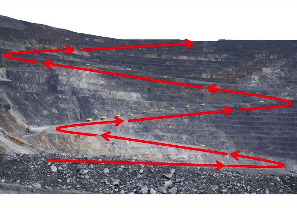
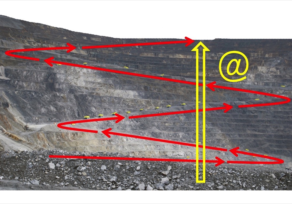
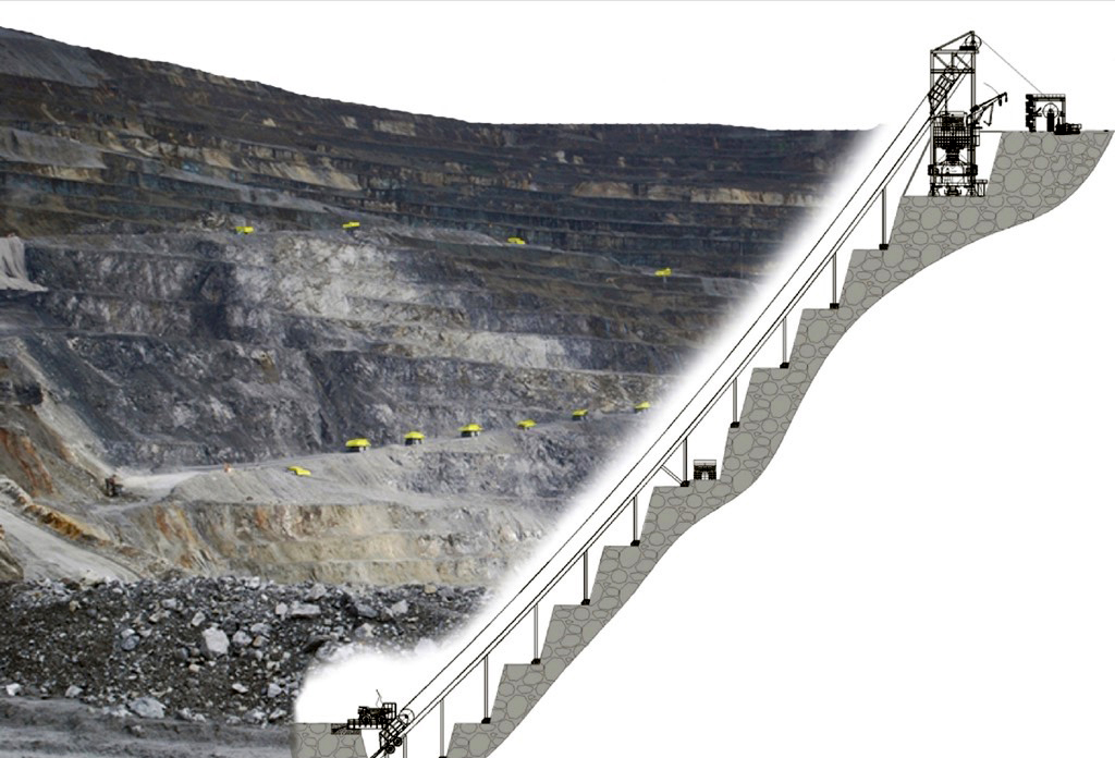
Fig. 1 shows a typical opencast mine for copper and gold ore with its steep banks and winding roads. The photo shows one of the world’s biggest copper/gold mines in Indonesia. It extracts and processes around 220,000 tonnes of copper/gold ore per day in truck/shovel operation. Looking at the photograph closely it can be seen that heavy-load trucks or mine trucks are moving up and out of the mine in a train-like formation on ramped roads, travelling at average speeds of around 15 to 20 kilometres per hour.The line of trucks works its way upwards on largely unpaved winding roads with gradients of up to 9 percent until it reaches the top of the mine. The trucks carry ore from the bottom of the mine to the crushing station at the top, as well as overburden to dumping areas outside the mine.
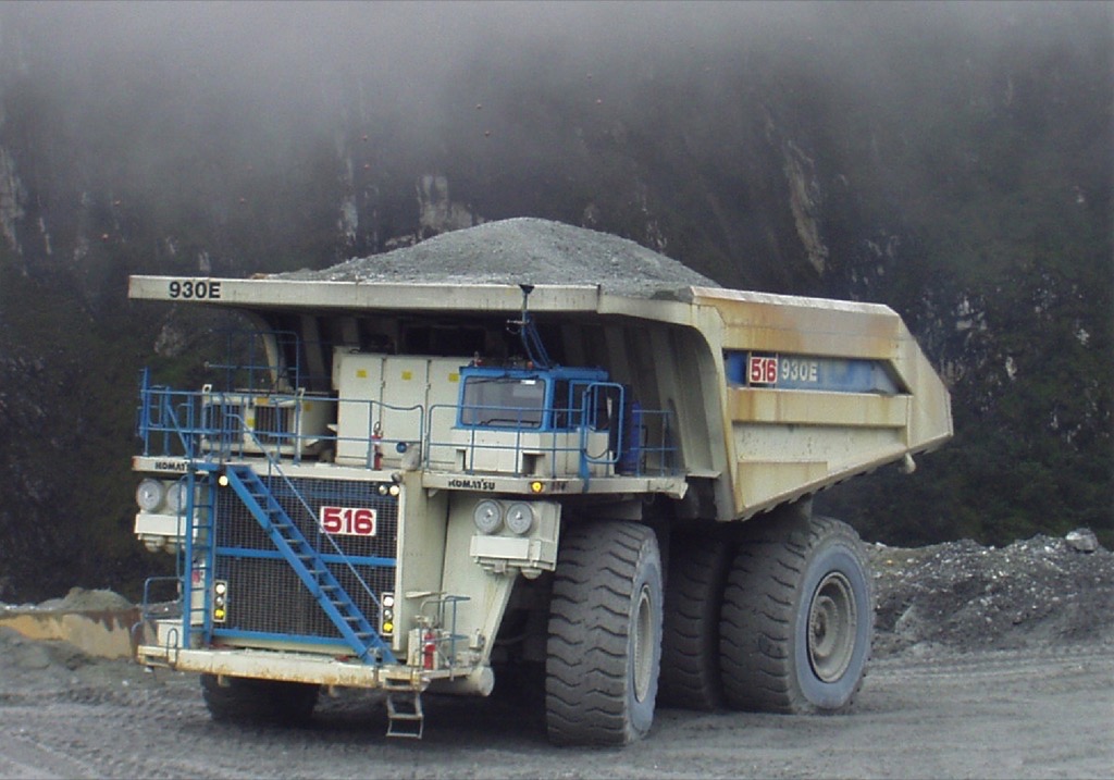
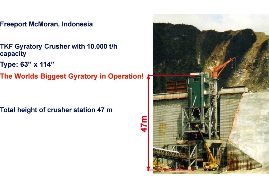
In the Freeport opencast mine in Indonesia, 6 crusher lines operate in parallel. Thyssenkrupp Fördertechnik equipped the mine with the world’s biggest ever gyratory crushers, of type 63"×114". To transport ore and overburden the mine uses a fleet of up to 220 trucks. The loading capacity of the individual trucks is between 240 and 400 tonnes. Fig. 2 shows one of these trucks with a load of fine ore. For a maximum payload of e.g. 240 tonnes the dead weight of the truck is already around 160 tonnes depending on truck manufacturer. So to carry 240 tonnes of payload, 160 tonnes of deadweight has to be moved.
A fleet of fully laden trucks drives up to the crusher station at the top of the mine. After unloading into the crusher or onto the overburden dump, the empty trucks drive back down into the mine by a separate route. One truck cycle in an average pit can take between 20 and 40 minutes.To reduce the truck fleet and the associated investment, labour and operating costs, larger trucks with payloads of up to 400 tonnes are being used as mines get ever deeper and distances ever longer (Fig. 3). A truck like this has an average deadweight of 260 tonnes and an installed diesel engine output of almost 3000 kilowatts.
Avoiding heavy-load Truck Traffic
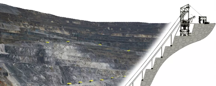
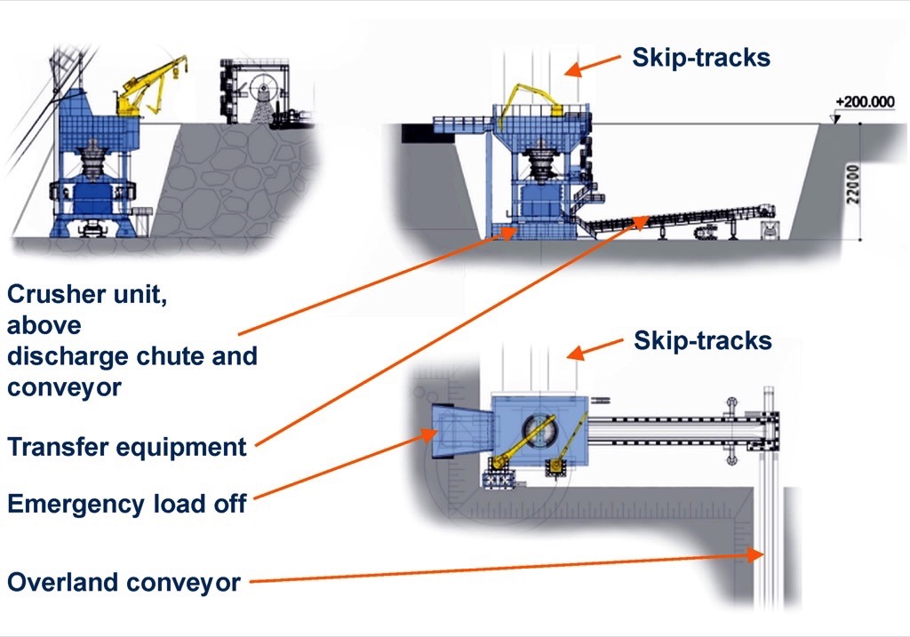
To avoid heavy-load truck traffic in inverted cone-shaped opencast mines Thyssenkrupp Fördertechnik is developing an integrated conveying and processing method described in detail in the following (see Fig. 4). To allow technical/financial comparison, the mine is assumed to have an incline of 45 to 55 degrees. The vertical rise for transporting overburden or ore is assumed to be 200 metres from the bottom of the mine or an intermediate level to the crusher station at the top.
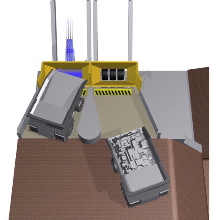
The conveying and processing system consists of an HLT (Heavy Load Truck) tipping station at the bottom of the mine (see Fig. 5), two skips running in opposite directions on a ropeway system with an average payload of 136 tonnes ore/overburden, and a track system for the two skips. At the top of the mine is a crusher station with headframe and discharge equipment for the crushed material. The electromechanical rope drive system is arranged separately from the skip emptying and crushing stations.
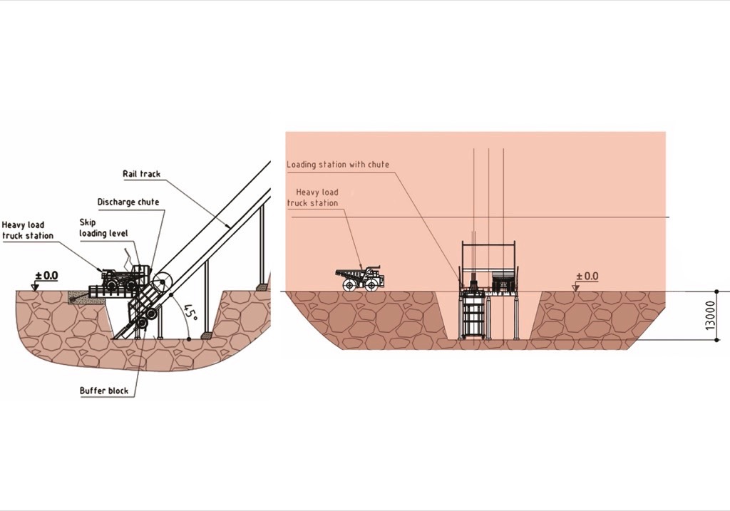
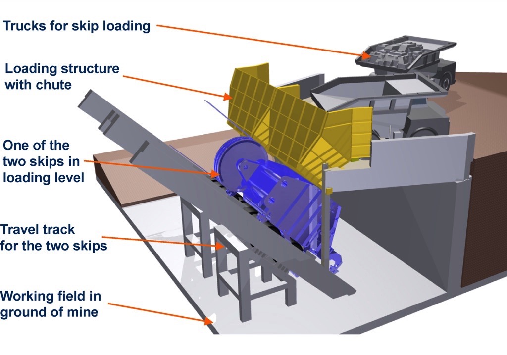
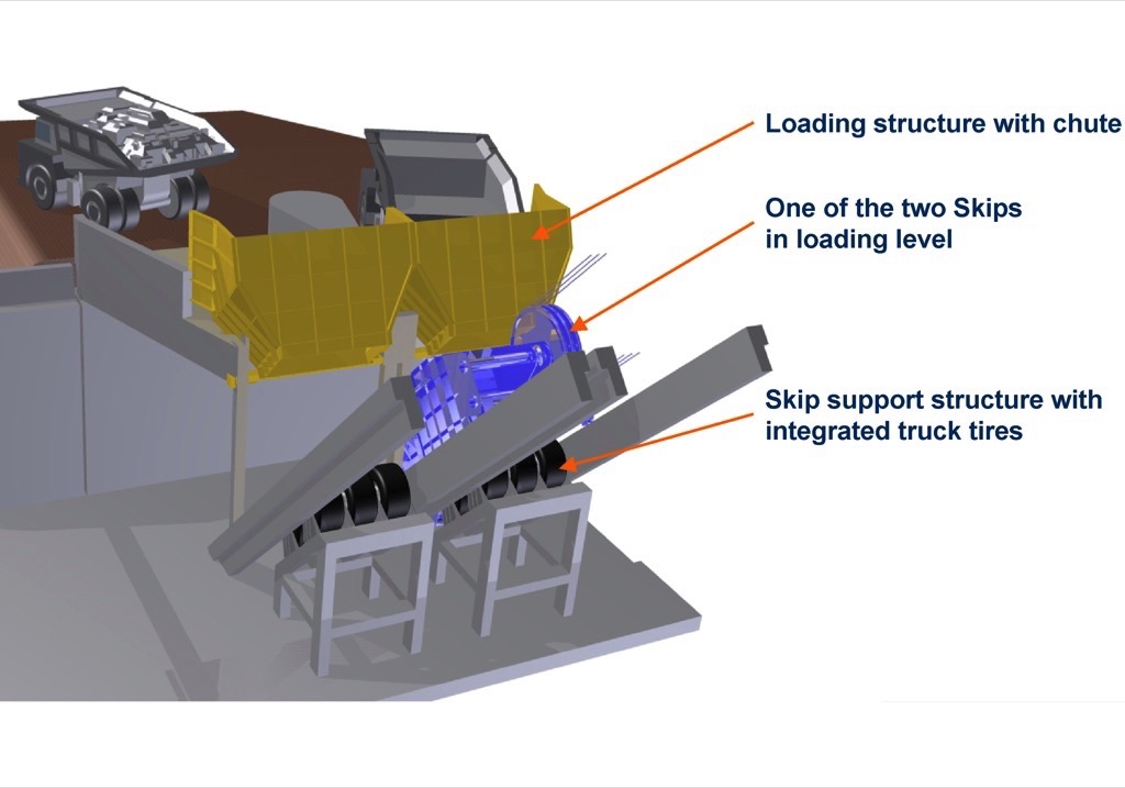
Trucks shuttle to and fro over short distances between the point of loading by the mine shovel and the feed station for the skip conveyor. Via an access ramp, loaded trucks reverse alternately into the tipping station. The skip is designed to take the full truck load plus a 10 percent weight tolerance. Dynamic loads caused by impacting material are absorbed among other things by the skip hanging in the rope system. Impacts on the skip discharge flap are cushioned safely by stationary pneumatic-tired buffer stations. During skip loading, rope sag on the transport section decreases and the ropes undergo additional extension. The resultant positional change of the skip, of up to 900 millimetres, is limited by a stop and is allowed for in the size of the opening of the feed chute.Figs. 6 to 8 show three views of the loading station in the bottom of the mine for illustration. Once the skip has been filled by a truck, it is pulled up on a track to the crusher station by a rope hoist, over a vertical rise of 200 metres.
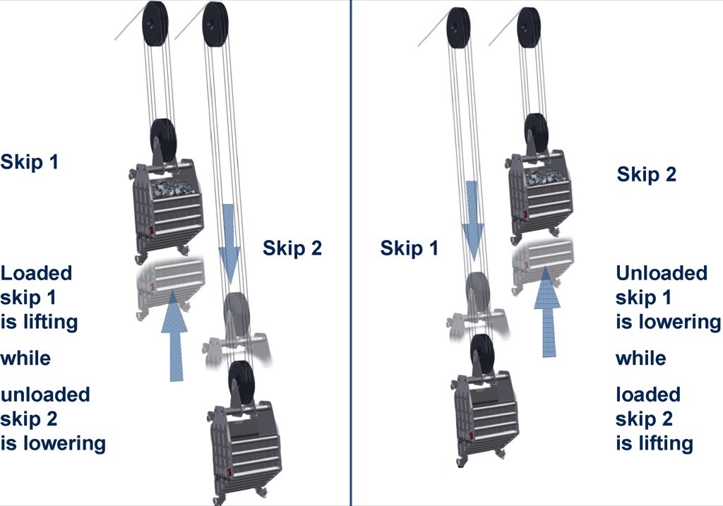
Similar to a freight elevator, as one loaded skip moves upward, an emptied skip moves in parallel downward to the bottom of the mine (Fig. 9). The two skips are connected via a rope system, rope sheaves and a traction sheave drive system at the top of the mine such that the dead weight of the skips is fully balanced and no unnecessary drive power needs to be expended. Once it arrives at the top of the mine 200 metres above, the loaded skip is moved into the crusher station emptying position with a predefined time lag (Fig. 10). At the same time the second – empty – skip is positioned in the skip loading station at the bottom of the mine.
The skip headframe with rope sheaves and steel structure is an integral part of a semi-mobile or stationary gyratory crusher station with feed bin, crusher and discharge conveyor. When the skip moves into the highest conveying position above the crusher feed bin, the skip discharge flap opens automatically or under remote control. Over a period of roughly 25 seconds the material drops out of the skip into the crusher storage bin. While this is happening the second skip is filled at the bottom of the mine.
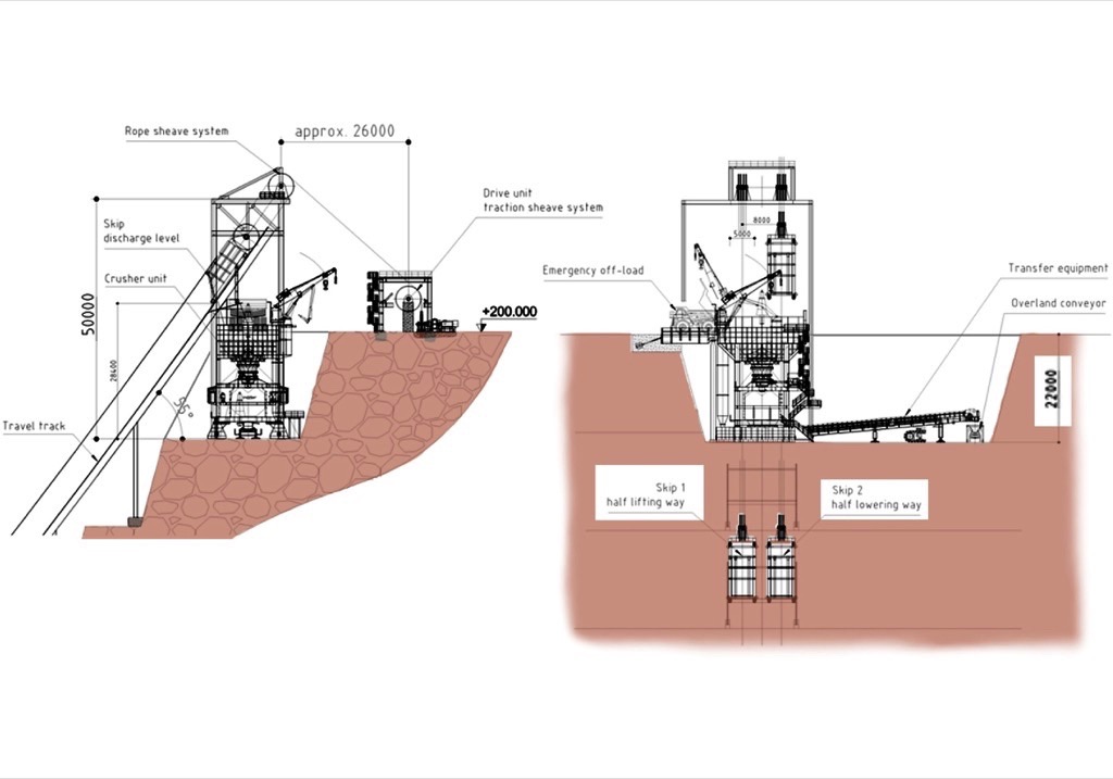
The crusher station is additionally equipped with an emergency or redundant truck charging system, a maintenance crane and a hydraulic breaker for breaking up oversize pieces of ore. Below the gyratory crusher is a discharge conveyor. This continuously feeds a conventional overland conveyor with crushed ore or overburden for transport away from the mine area. The rope drive system is anchored in a separate station roughly 30 metres away from the crusher and the edge of the mine. The overall height of the crusher station with headframe is roughly 50 metres.
Crushing at Freeport Mine, Indonesia
Thyssenkrupp has three crusher stations in operation in the Freeport mine in Indonesia (Fig. 11). Ore and overburden are crushed by the world’s biggest ever crushers of type 63"×114". A single crusher station has a capacity of 10000 tonnes per hour. The overall height of the crusher station is 47 metres, almost comparable with the height of the crusher/skip system described here. Fig. 12 shows the three views of the crusher station at the top of the mine, roughly 22 metres below the skip emptying position.
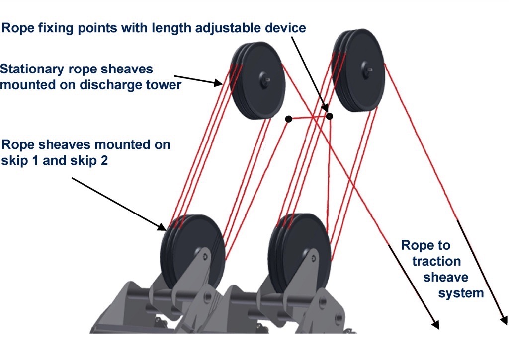
To reduce the rope load and limit the drive moments, each skip is suspended in a hoist. In the present case the rope has a diameter of 54 millimetres and runs over six rope sheaves per skip with a sheave diameter of 4320 millimetres (Fig. 13). The two rope ends are firmly anchored in the headframe by means of an adjustable length compensation system.
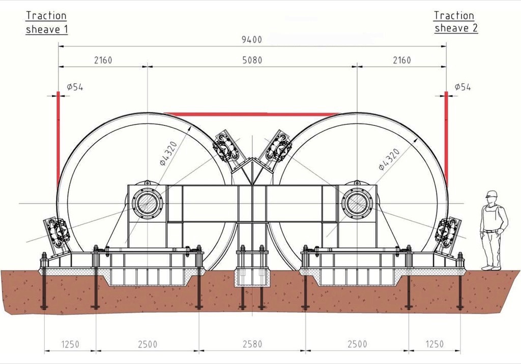
The rope leading from the hoist in the headframe runs over a diverter sheave in the drive station and is led over two double-groove traction sheaves and a further diverter sheave to the second skip hoist. The drive moments of the two 1300 kilowatt rated motors are transmitted without virtually any slip through a total loop of 540 degrees by the two yellow traction sheaves (Fig. 14).
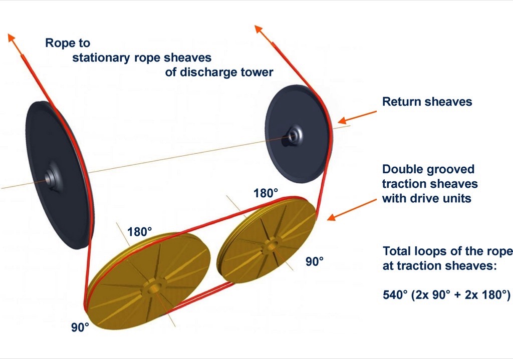
Fig. 15 shows a top view of the two identical drive units, Fig. 16 shows the side view of one of those units. The front view of the two drive units is shown in Fig. 17.
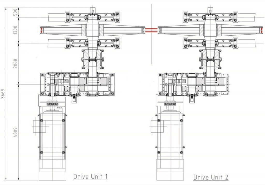
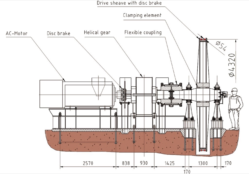
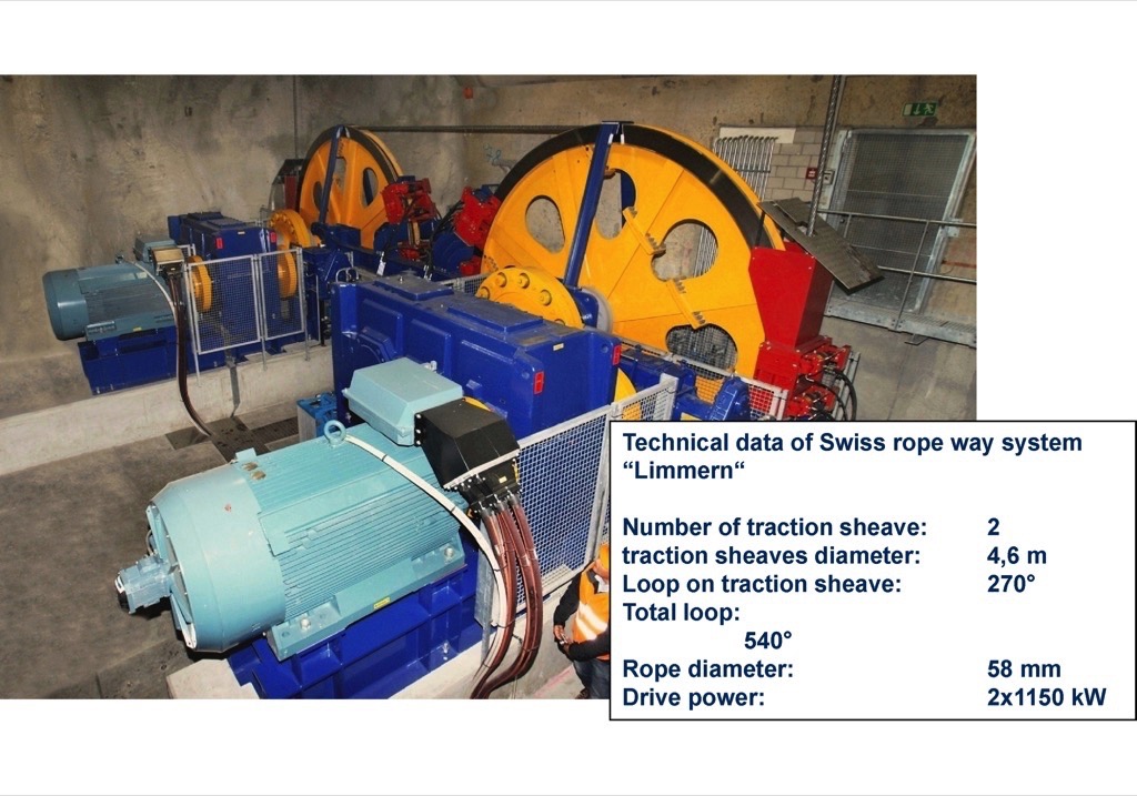
Each drive train consists of a variable-frequency asynchronous motor, a disc service brake, a helical gear unit, a flexible coupling and a double-groove rope sheave fixed to the drive shaft by clamping elements. The diameter of the rope and traction sheaves is determined among other things by the German mining standard TAS (Technical Requirements for Shaft and Inclined Haulage Systems). This requires the ratio of sheave diameter to rope diameter to be greater than or equal to 80. For a 54 millimetres rope a sheave diameter of 4320 millimetres was chosen. The rope safety factor is greater than seven. In addition to the service brakes in the drive train each traction sheave is fitted with safety or holding brakes.The two-sheave drive system is not new. It has proved successful in numerous heavy-duty elevators and ropeway systems. Fig. 18 shows a typical ropeway drive system in Switzerland. The drive power is 2 × 1150 kilowatts, the rope diameter 58 millimetres and the sheave diameter of 4.6 metres.
Skip Design Details
In this concrete case the skip for a truck load of 136 tonnes (75 cubic metres) of ore is 4 metres wide, roughly 13 metres long and has a fill height of 5 metres (Fig. 19). The skip has a design capacity of 90 cubic metres and requires a deadweight of around 90 tonnes to guarantee power transmission in the rope drive system. The quantity and size of the bogies are determined by the steepness of the track, the rail profile and the admissible wheel contact pressure. In this case a two-wheel bogie with 710 millimetre wheels was provided at each skip corner, matching the A100 rail. Side guide rollers are additionally fitted on each bogie.
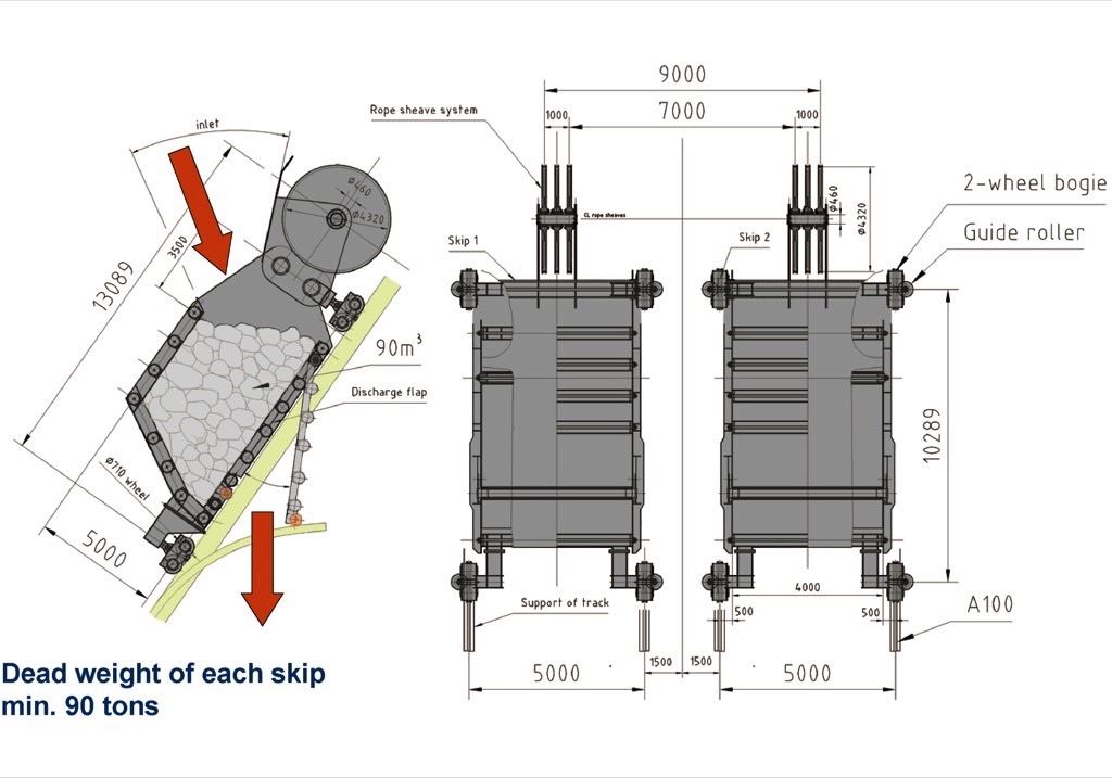
Ore is fed into the skip through an opening below the rope sheave system. When the skip moves into the emptying station the discharge flap automatically opens to discharge the material. The skips have a locking mechanism on either side for unlocking and locking the discharge flap (Fig. 20). Once the skip reaches the topmost conveying position an external actuation mechanism releases an unlocking system and the pressure of the material immediately opens the discharge flap. Once the skip is emptied after around 25 seconds and the trip down has begun the flap is closed by two guide rollers and safely locked.
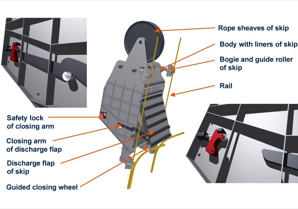
Fig. 21 shows a typical work cycle from skip loading to unloading. For a rise of 200 metres on an incline of 45 to 55 degrees the skips have to cover a total distance of 285 metres. With a maximum rope speed of around 11 metres per second and 6-part reeving, the skip speed is 1.9 metres per second (around 6.9 kilometres per hour). Skip loading takes 25 seconds and occurs while the second skip is emptied at the top station. Skip acceleration and deceleration require 5 seconds. A complete conveying cycle from loading to unloading therefore takes 180 seconds or 3 minutes; i.e. trucks with 136 tonnes of payload can drive into the tipping station at the bottom of the mine every 3 to 5 minutes.
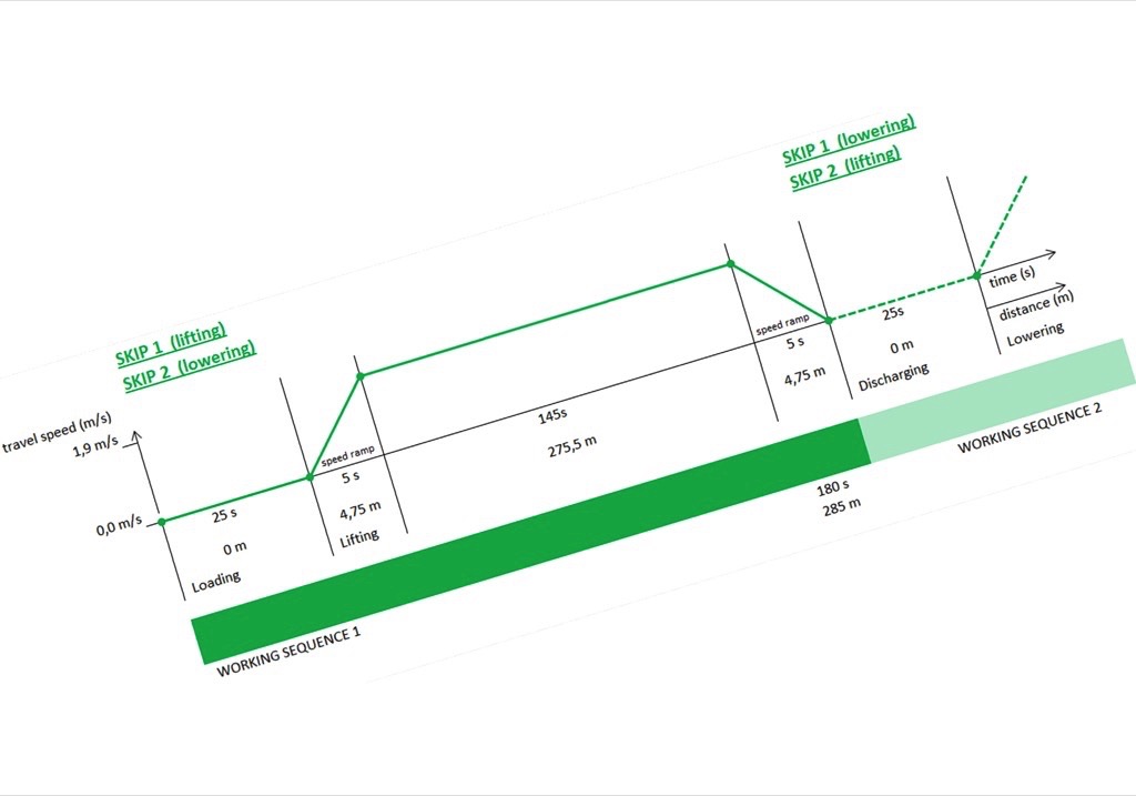
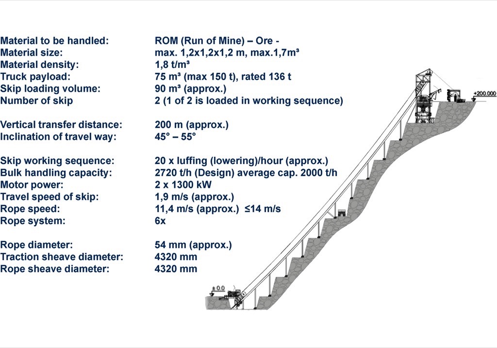
Fig. 22 summarises the design of the conveying and crushing system for the chosen example.
Comparison of Transport Methods
A system was analysed to convey ore with an average density of 1.8 tonnes per cubic metre. Trucks with an average payload of 136 tonnes are used to load the skips. The vertical rise is 200 metres over an incline of 45 to 55 degrees. The rope system and drive system with 2 × 1300 kilowatt drive power is designed for 20 cycles per hour and a handling capacity of 2720 tonnes per hour. It can be assumed that this design will be capable on average of conveying over 2000 tonnes per hour of ore or overburden.Table 1 compares typical parameters of the two systems “skip conveying” and “truck traffic”.
| Skip – Conveying | Truck Traffic | |
| System | 2 Skip 136 tonnes | 7 × Trucks 136 tonnes each |
| Transport – Distance | 0,29 km (55° slope) | 2 × 2,5 km (4,6° slope (8%) |
| Transport Efficiency (moved playload / moved power effective total load) | 100% | 37% (136 / (2 × 113,5 + 136) |
| Ratio Payload / Truck Weight | – | 136 / 113,5 = 1,2 |
| Total Installed Power | 2 × 1300 = 2600 kW | 7 × 1082 = 7574 kW |
| Ratio of Installed Power Skip System /Truck Traffic | 1: 2–3 | |
| Manpower (without crusher operation and maintenance staff) | 0 | 20–25 Truck driver per day + 1 Waterspray truck driver + 1 Grader driver (road-refurbishment) |
| C02 – Reduction compared to Truck System | 29.000 kg C02/day | – |
For an average handling rate of 2000 tonnes per hour of ore, seven trucks with a payload of 136 tonnes must each travel 2 × 2500 metres on a road with an incline of 8 percent or 4.6 degrees to overcome a vertical rise of 200 metres.If the moved payload is set in relation to the deadweight of a truck, which must be multiplied by two due to the empty trip back into the mine, the transport efficiency for the trucks is just 37 percent. The ratio of payload to truck weight of 1.2 is very unfavourable. With the skip system the deadweight of the skips is completely balanced. The drive system does not have to expend additional energy to transport the empty skip.The comparison of installed power shows 2600 kilowatts for the skip system and 7 × 1082 kilowatts = 7574 kilowatts for truck traffic, giving a ratio of installed power of 1:2 to 3.If we compare the use of manpower – excluding crusher and maintenance personnel – 20 to 25 truck drivers per day will be needed for multi-shift mine operation, plus one driver each for a water spray truck and a grader for road upkeep.One significant factor with the two systems is their CO2 footprint. If a skip conveyor system is used instead of the truck system in the example discussed with a handling rate of 2000 tonnes per hour of ore, CO2 emissions can be reduced by up to 29 tonnes per day.
Conclusion
The combination of tested technologies for the use of a skip conveyor offers:
- The shortest conveying distance through use of a steep incline conveyor.
- Up to 50 percent lower transport costs within a mine.
- Energy saving: Energy needs to be expended only for transporting the payload. The deadweight in the system is completely balanced by the second, empty skip.
- The crusher station can be positioned at the top of the mine or at an intermediate level.
- Significant reduction of CO2 footprint due to reduced truck traffic.
- Environment-friendly technology with minimum noise and dust emissions.
- Higher availability as the system remains fully available in bad weather conditions (snow, fog, rain).
- Reduced costs for mine road upkeep and maintenance of remaining trucks to supply ore to the skip system.
- Lower operating and personnel costs. Lower investment costs as the truck fleet can be significantly reduced.
As mentioned at the beginning, Thyssenkrupp Fördertechnik is currently developing* this innovative skip conveying system with integrated ore/overburden crushing. The company is studying the design of drive and conveying components as well as investigating technical implementation for a suitable mine. Obviously such a system would have to be adapted to actual mine conditions and the technical/financial aspects of using the system would have to be clarified in advance – together with the mine owner.
* A Note from the Editor
For all statements in this article that refer – directly or indirectly – to the time of publication (for example “new”, “now”, “present”, but also expressions such as “patent pending”), please keep in mind that this article was originally published in 2012.
| About the Author | |
| Dr. Ing. Franz M. WolpersHead of Materials Handling Germanythyssenkrupp Industrial Solutions, Germany |
■

