
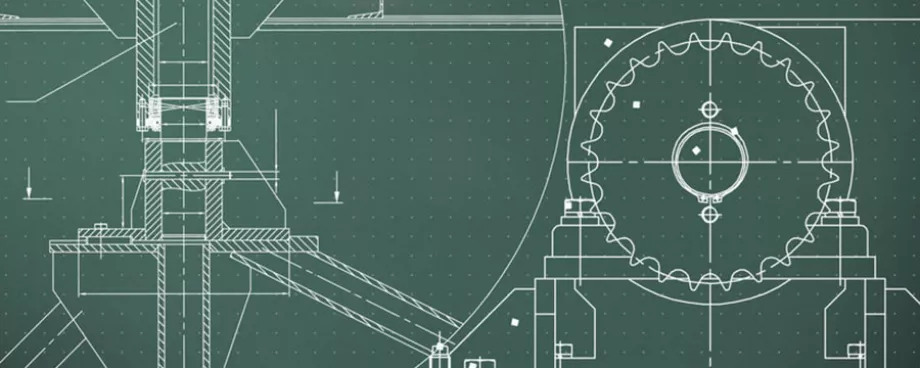
(From the archive of ”bulk solids handling", article published in Vol. 36 (2016) No. 2/3 , ©2016 bulk-online.com)Quarries and open-pit mines for ores, building materials, minerals and coal are often characterized by steep terraced slopes formed over many decades by blasting and material removal. Depending on the stability of the ground a slope angle is chosen that will prevent slippage, particularly in loose rock and in regions at risk of earthquakes.The terraced slopes with inclines from 25 to in some cases 75 degrees are intersected by slowly rising roads that carry heavy truck traffic and also secure access to the mine. The serpentine roads generally have two lanes or feature lay-bys to allow two-way traffic. Maintaining these roads is complicated and costly. Larger open-pit mines use heavy load trucks with deadweights from 106 to 260 t and payloads of 136 to 400 t and more.In quarries and smaller ore, mineral and coal mines, all-terrain trucks are also used for haulage, usually with payloads of 40 to 100 t. The trucks transport uncrushed material from the bottom of the mine or distant mining areas. They travel on unpaved, often muddy, gently rising haul roads with gradients of roughly 4.6 degrees to a tipping area outside the mine or a crushing and processing station near the edge of the mine. The distances the trucks have to cover are therefore long. Based on an average speed of 15 – 20 km/h a truck cycle can take almost an hour.Thyssenkrupp – known among other things as a global supplier of mining, mineral processing and materials handling systems – has now developed a new steep-angle conveying system that makes it possible to transport hard rock, ore or overburden from a mine more efficiently by the shortest direct route while at the same time significantly improving the CO2 footprint of the mine (Fig. 1).
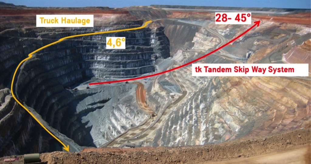
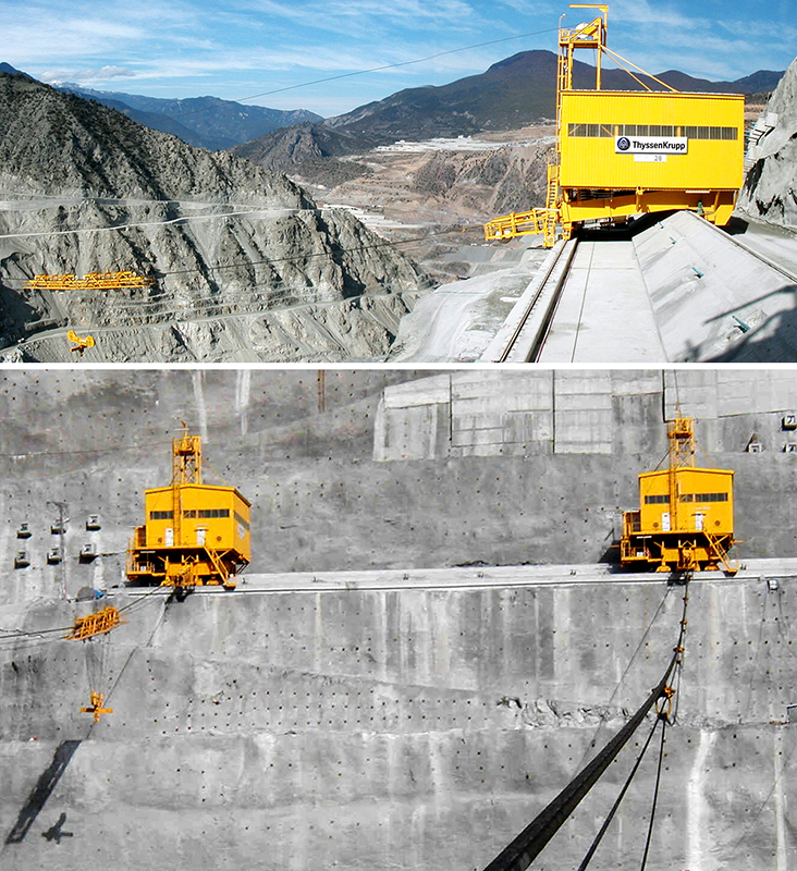
The system and process, for which patents have been filed, are based on well-known and proven cable crane technology from thyssenkrupp and reduce the use and number of heavy load trucks in an open-pit mine. With the thyssenkrupp system, the trucks travel only relatively short distances – and without major gradients – between the truck shovel loading station and the unloading point at the steep conveying system. For a given handling capacity the number of trucks in a mine can be reduced, with an associated reduction in capital, operating and manpower costs.Even if diesel costs are relatively low at present, it has to be assumed in light of rising energy requirements and increasing fuel scarcity that world market prices will rise again soon. In addition, standards on environmental protection and resource conservation are being raised worldwide. Both aspects will also impact on the sustainability and profitability of existing open-pit mines.The skip way system is based on the technology of cable crane systems (Fig. 2), which are used in the construction of large dams and are also part of the wide product range offered by thyssenkrupp.
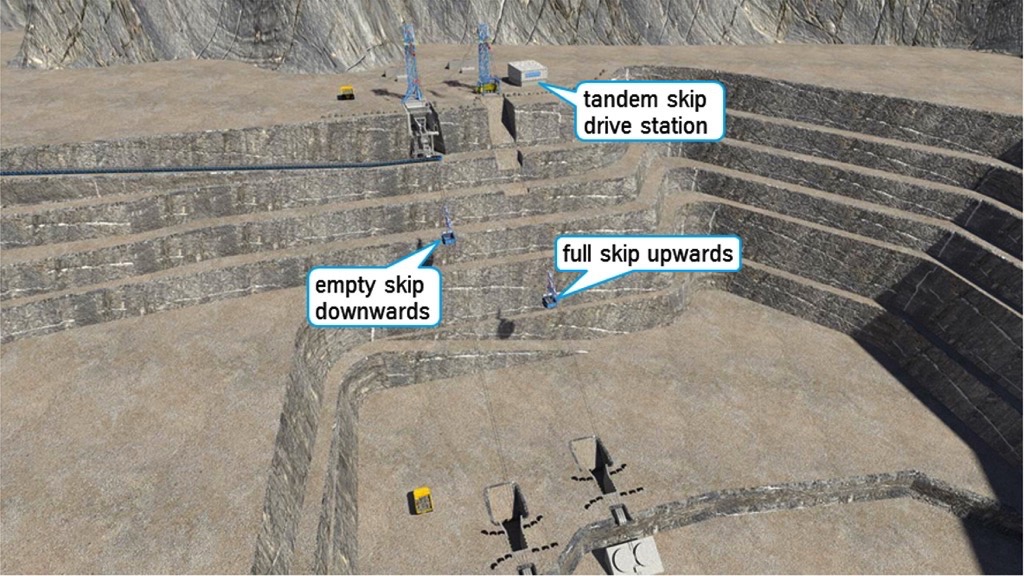
At two truck unloading stations at the bottom of the mine (Figs. 3 and 4) skips running in opposite directions are charged with uncrushed material by dump trucks.
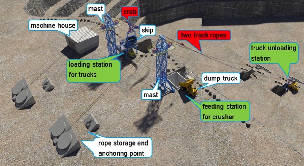
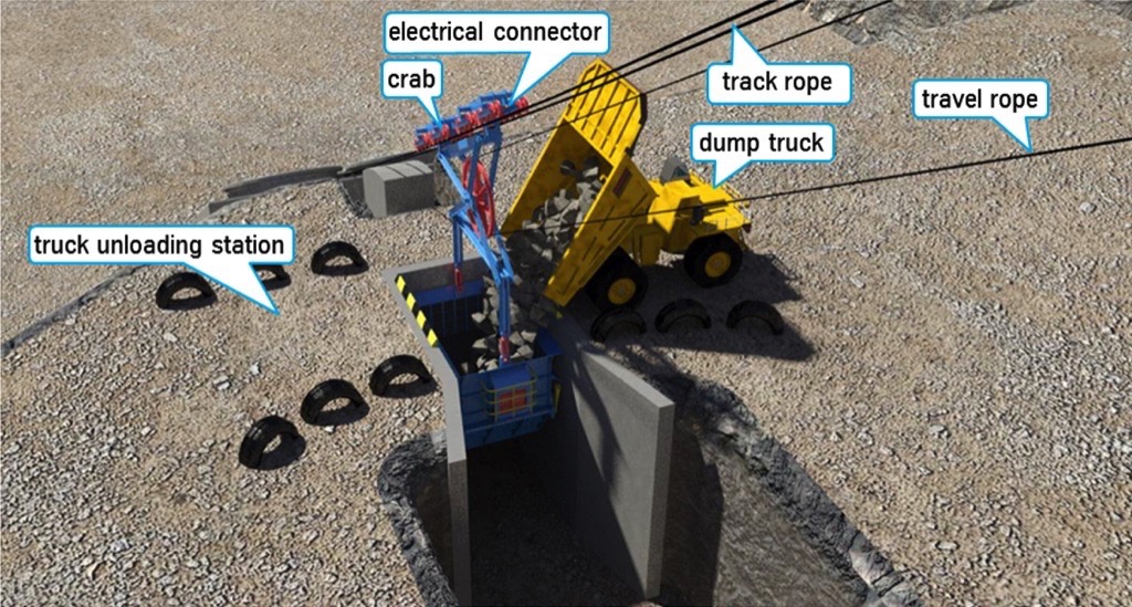
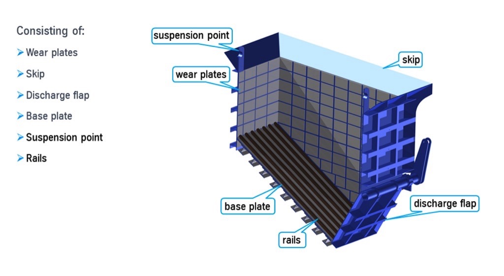
The skips are fitted with wear plates and slide rails and are suspended in a vibration-damping support frame and carriage assemblies from two parallel track ropes in each direction (Fig. 5 and Fig. 6).
The full locked ropes are anchored in the ground near the bottom station and span the entire slope of the mine up to the skip unloading station at the top without any intermediate supports. At the top of the mine the ropes are led over a mast and anchored either in the ground or in a counterslope. The run of the ropes from the bottom station to the top station is determined by the position of the unloading station near the edge of the mine, the deadweights of the ropes, the rope tension and resultant sag, and additionally by the upward or downward running skips (Fig. 7 and Fig. 8). Rope tension is set so that both laden and empty skips maintain a safe distance from the mine slope and any roads leading into or out of the mine.
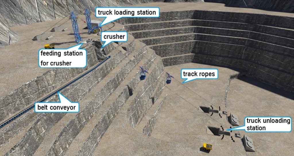
The two parallel rope anchor stations at the rear of the skip unloading stations serve as tensioning and storage systems for additional rope lengths should the bottom station be relocated as mining progresses.The use of two parallel track ropes in each direction allows the use of standardized – still common – full locked ropes. Two track ropes result in a shorter skip carriage as the number of running wheels needed to distribute loads is divided over two ropes. Polyamide running wheels, already proven in cable cranes, are used to reduce wheel-rope contact pressure and maximize rope life.The skip way system offers several options for skip unloading at the top station. As shown in Fig. 9, valuable ore or minerals can be transported on one rope system so that automated skip discharge takes place in this part of the conveying system above a crusher. Once the locking mech-anism opens, the entire skip load of uncrushed ore or mineral slides into the crusher bin. After crushing and possibly screening the raw material is transported out of the mine area via a conventional belt system for further processing or for example to a cement plant.
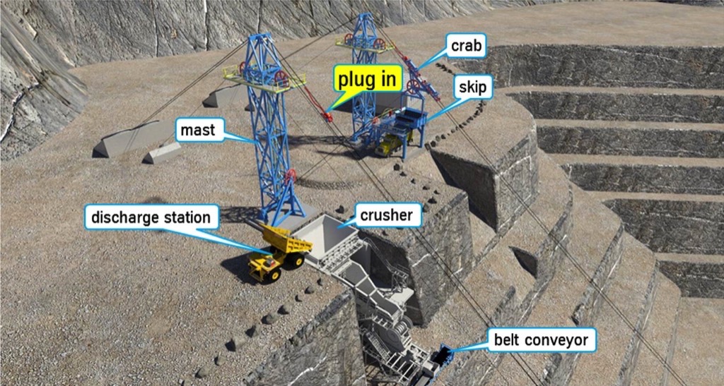
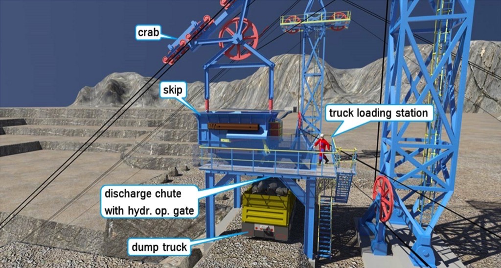
The second rope track of the Skip way system can be used for example to transport uncrushed overburden, which is loaded from the skip back onto mine trucks at the top station (Figs. 9 and 10). The trucks can then transport their load to the overburden dump on virtually flat roads. As most mines and quarries already have nearby screening and crushing stations, both skip unloading stations at the top of the mine could also be used for truck loading and onward transportation.
The skips are connected by a common travel rope and transport valuable raw material or over-burden out of the mine within preselected travel cycles. As one skip is being loaded by a dump truck at the bottom station, the second skip is located at the top station above the crusher or the truck loading point. Fig. 11 illustrates the run of the travel rope of the upward travelling skip and the run of the rope over a deflector sheave in the first support mast of the first unloading station up to the separate drive station at the side.
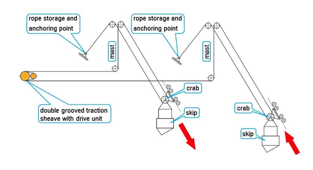
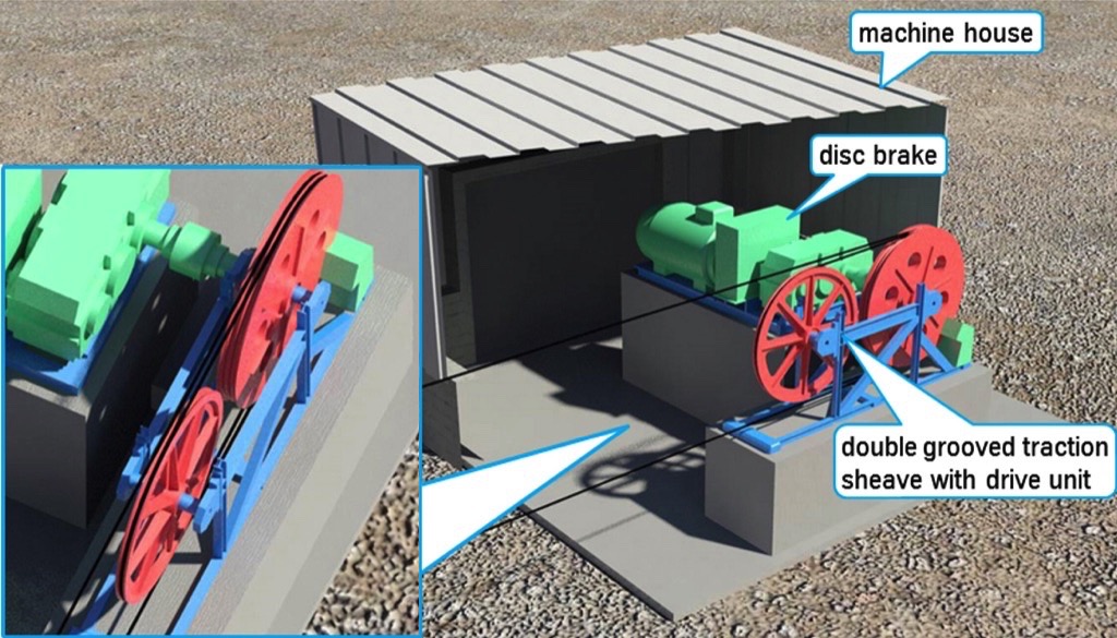
Inside the drive station (Fig. 12) the travel rope is passed over a double grooved traction sheave with countersheave and is driven by friction through a wrap angle of 2 x 180 degrees. The travel rope drive unit is a conventional wrap drive of the type used in rope or cable cranes. Its main components are a variable-frequency induction motor with spur gear unit and service brake, and a double grooved traction sheave with emergency brake. The entire drive station sits on a concrete foundation close to the ground and is easily accessible for inspection and maintenance. The switchgear and controls for the skip way system are located in the machine house.
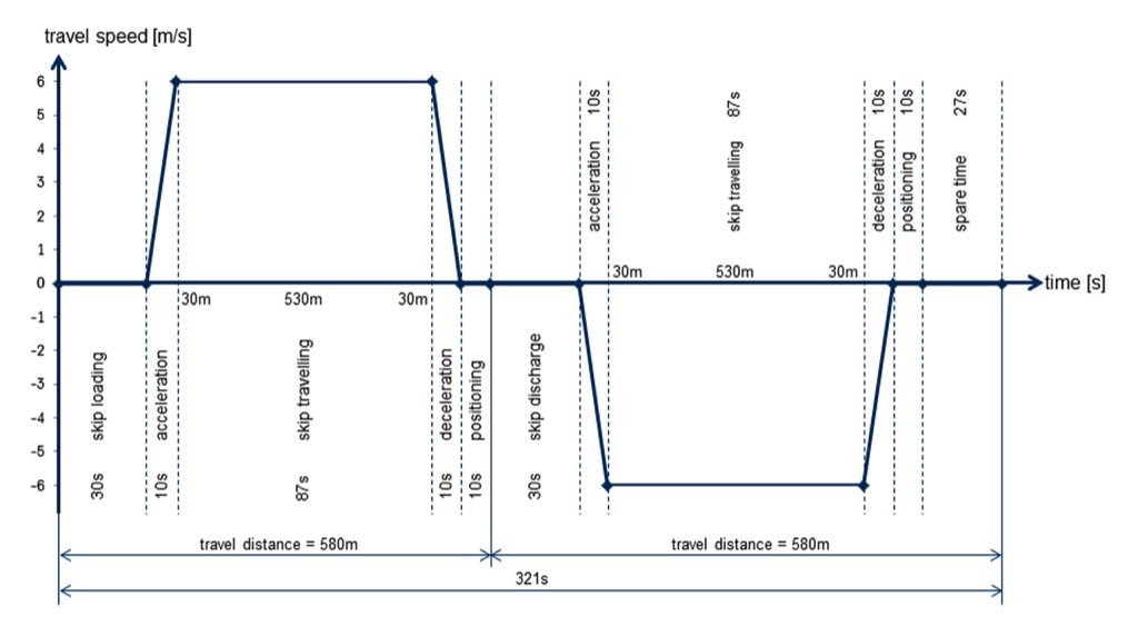
From the drive station the travel rope passes over a deflector sheave in the second mast station to the downward travelling counter skip. Both ends of the travel ropes, like the track ropes, are anchored in the ground or the mine slope at the rear of the unloading stations. If the truck unloading station at the bottom of the mine is moved, the necessary additional rope length can be drawn from this rope storage point.A typical travel cycle for this steep conveying system with 1000 t/h handling capacity, a vertical lift of 410 m and a roughly 45° slope is shown in Fig. 13. 30 seconds are allowed for skip loading at the bottom of the mine, 10 s for skip acceleration and roughly 87 s for the actual travel distance of 530 m. 40 seconds are planned for simultaneous skip deceleration and positioning in the loading and unloading stations. With a calculated cycle time of 321 s the system would still have a time reserve per cycle of 27 s. This spare time is available as additional skip waiting time for truck positioning in the dumping station.
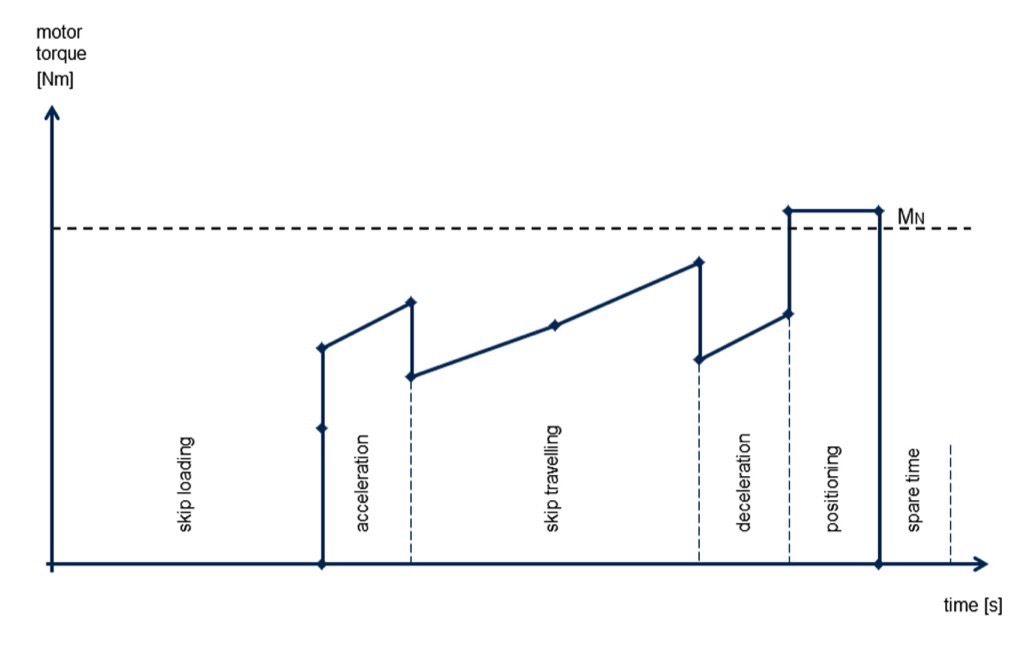
As an example Fig. 14 shows the torque curve of the drive motor for a skip upward trip, taking into account deadweight compensation by the second, empty skip travelling downwards at the same time. The motor’s rated torque is reached/exceeded only very briefly when the laden skip is positioned slowly in the top station. Due to the different angles of the track ropes in the stopping stations, torque equalization by the dead loads of the skips is no longer fully possible.
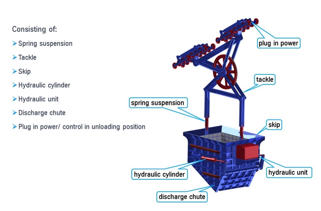
The bottoms of the skips are protected against wear and impact deformation by clamped-on railway rails (Fig. 5). The honeycomb-shaped skip sidewalls are lined with replaceable wear plates, so the robust basic structure of the skip can be maintained over many years of operation through replacement of worn plates and rails. Impacts from individual boulders measuring up to 1 m diagonally and weighing up to around 1 ton are absorbed by the steel structure without permanent deformation. This has been demonstrated by FEM analyses and is to be verified in practical tests on a 3 x 4.2 m skip baseplate subjected to a load of one ton dropped from a height of 4.5 m. In addition, the initial impact of an ore or stone boulder on the baseplate is cushioned by the formation of a bed of fines between the wear rails, supported by the spring-loaded suspension of the skip in the support frame and subsequently also by the yielding of the track rope line (Fig. 6).After the skip is positioned in the top station the discharge flap of the skip is opened by two side-mounted hydraulic cylinders with slowly increasing extension speed. Finer material empties through the initial opening. As the opening becomes larger coarser material and individual boulders slide out of the skip into the crusher station bin or onto a waiting truck. The hydraulic closing and opening mechanism is mounted on the skip and is activated in discharge position by a plug in power/control contact (Fig. 6). Opening and closing of the discharge flap takes place fully automatically above a crusher station, whereas operator control is envisaged for truck re-loading.Characteristic design data for a skip way system in a kimberlite mine are shown in the example in Fig. 15.
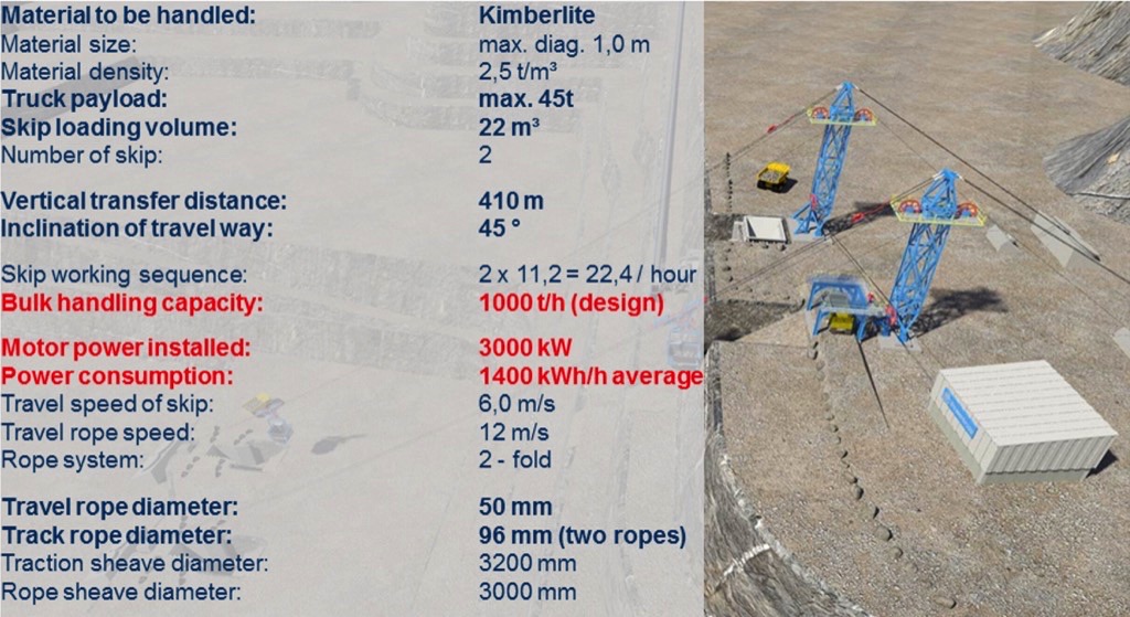
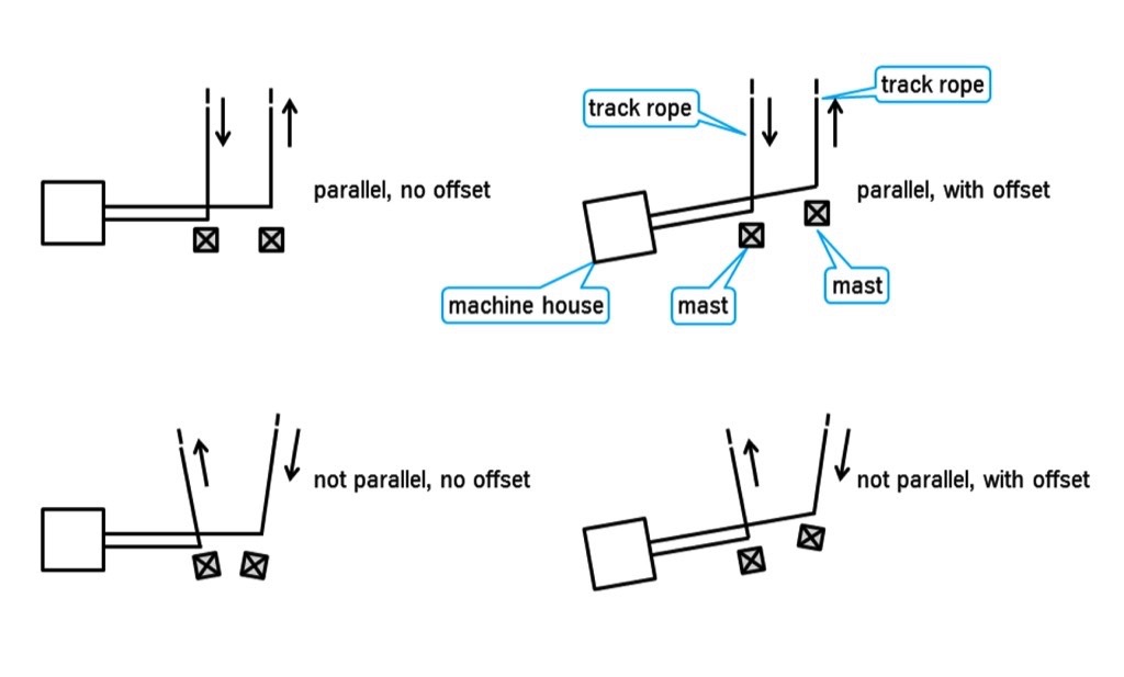
In the example presented, uncrushed kimberlite with a density of 2.5 t/m³ is transported by a tandem skip way system a vertical distance of 410 m over a slope with an average incline of 45°. The mine trucks have a maximum payload capacity of 42 t, so the skips were designed for a capacity of 22 m³ or 45 t max. With a conveying distance of 580 m and a chosen travel rope speed of 12 m/s, this results in 11.2 travel cycles per hour and rope system for a handling capacity of 1000 t/h.Due to the heavy masses to be accelerated and positioned the drive motor is designed for a power output of 3000 kW. During the steady-state phase, i.e. during constant skip travel, skip deadweight compensation comes fully into play, so the average power requirement – over the full travel cycle – will be only 1400 kW. The deadweight of a skip including deflector sheave and tandem carriage for a maximum payload of 45 t is 37 t; of this, as much as 22 t is accounted for by the skip and hydraulic unit. This relatively high deadweight is necessary to absorb the heavy impacts of individual boulders during loading, but it also serves to tension the travel rope in the wrap drive (Fig. 12). The dead loads of the two skips do not need to be considered, as the masses cancel each other out exactly in operation. The travel rope connecting the skips runs over the traction sheave with a speed of 12 m/s and moves the skips after single deflection by a sheave in the skip carriage with a maximum speed of 6 m/s.The travel rope is 50 mm in diameter and the two full-locked track ropes in each strand are 96 mm in diameter. In accordance with the relevant design standards the design of the rope and the rope diameter require a traction sheave diameter of 3200 mm and deflector sheaves with 3000 mm diameter.Depending on vertical lift and travel distance a skip way system can handle up to 2000 t/h. The actual handling capacity and hence the maximum truck payload is limited to 60 t per skip and is determined by the rope construction, rope breaking strength, rope diameter and the allowable wheel pressure on the track rope.Thyssenkrupp’s skip way system is highly adaptable to the topography of the mine. Depending on the location of haul roads, the configuration of the edge of the mine, the slope and space conditions at the bottom and exit of the mine, the drive station can be arranged in different ways relative to the unloading stations in the mine. The spacing and orientation of the two masts and thus of the truck loading and crushing stations can also be varied to suit local conditions. Examples of possible layouts at the rim of the mine are shown in Fig. 16. The spacing of the truck unloading stations at the bottom of the mine and the angle of the rising track ropes can naturally also be varied.
The skip way system has been designed for efficient use as a steep-angle conveying system in quarries and smaller but deep open-pit mines. The system ideally complements the “Integrated Crushing and Skip Conveying System” [1] with handling rates of up to 5000 t/h for uncrushed ore or overburden (Fig. 17) previously presented by Thyssenkrupp. In this system skips run in opposite directions on a steel track over a steep slope and can either empty their pay-loads of up to 250 t into the feed bin of a semi-mobile crusher or re-load ore or overburden onto correspondingly large mine trucks via a special bin station with apron conveyor discharge.
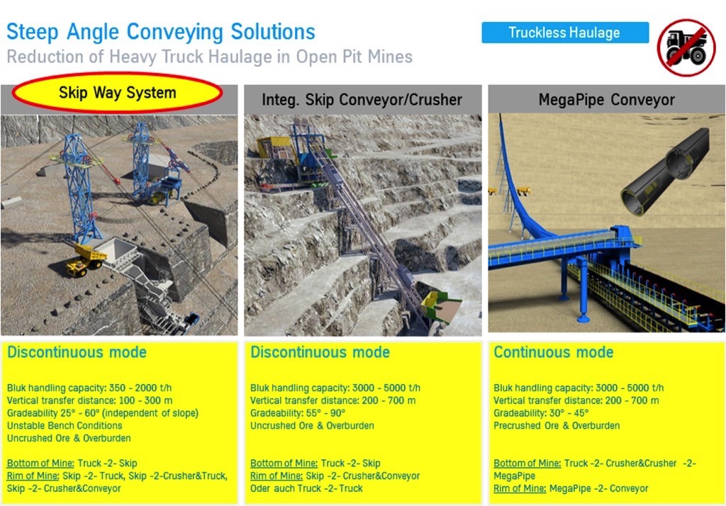
This conveying system requires stable ground and there should be no danger of earthquakes and landslides. If there is already a semi-mobile crusher station at the pit bottom or on an intermediate level, a third steep-angle conveying option could be advantageous. Together with the German companies Continental and Siemens, Thyssenkrupp is currently developing a continuous steep-angle conveyor, based on pipe conveyor technology, that can transport pre-crushed ore or minerals from depths of 200 to 700 m up a 30-45° slope at rates of up to 5000 t/h. The s–shaped track is located in the slope by means of a steel structure.The pipe belt conveyor has an inside diameter of 900 mm. The center of the belt has a chevron pattern that prevents bulk material and individual lumps up to roughly 350 mm edge length from sliding back at such a steep conveying angle. After material transfer at the pit rim, onward transportation is by means of conventional overland conveyors with troughed belts. Details of the design of this conveyor system are provided in this issue on page 30 [2].Fig. 17 summarizes the main data and possible uses of the three conveyor systems.Returing to the Thyssenkrupp skip way system, the advantages of the system for handling rates up to 2000 t/h and maximum truck payloads of 60 t can be summarized as follows:
- Reduction of haulage costs in quarries and in smaller but deep open-pit mines
- Reduced operating and manpower costs
- Reduction of capital and operating costs over mine life (capex, opex)
- Reduced expense for building and maintaining roads in and out of the mine
- Single-lane roads – instead of two-lane roads to allow two-way traffic – are sufficient and permit steeper slopes and therefore either higher recovery of valuable minerals or less removal of overburden
- The skip way system can also be used in very rough weather conditions when truck haulage might have to be suspended (fog, snow, ice and rain)
- Use of the system provides a significant reduction in noise, dust and CO2 compared with truck haulage and could help in retaining mine operating licenses
- The system lends itself very well to partial or full automation
- In contrast to the alternative systems presented in Fig. 17 the thyssenkrupp Skip way system can also be employed in earthquake-prone regions or mines with unstable slopes, as the rope support masts are located off the mine slope and are anchored flexibly in ground foundations using pins. From the mine bottom to the unloading station at the top no further support structures for the track and travel ropes are required
- Existing pit slopes do not generally need to be adapted for subsequent installation of the system, nor is it necessary to relocate existing access roads into the mine
- The system allows the re-loading of trucks in the case of overburden (truck to truck operation) or the parallel charging of a crusher and processing station in the case of valuable minerals (truck to crusher operation)
- As mining progresses the bottom station can also be relocated to greater depths as the necessary additional rope lengths are stored at the anchorage points when the system is first installed
- The entire system including loading, unloading and drive stations can also be relocated as soon as new anchorage points have been concreted in the mine
- If the system is used to feed a crusher station at the mine rim, mine trucks from other mines or higher mining areas in the same mine can also use the crusher’s bin feed system (Fig. 9). This provides further redundancy during inspection and maintenance of the skip system.
The Thyssenkrupp skip way system is a cost-effective and eco-friendly steep-angle conveying technology that can be integrated easily into existing steep open-pit mines or quarries. Many mine operators using truck haulage will face increasing production costs as their mines get deeper. The new steep-angle conveying system now offers an ingenious, cost-effective alternative to truck haulage. Obviously such a steep-angle conveying system will need to be adapted to the conditions of an existing mine and the technical/financial aspects (capex/opex) will need to be clarified in advance – jointly with the mine operator.
References:
- Wolpers, F.: Skip-Conveying in Opencast Mines - TKF’s Technology Approach to optimize the Cost and Energy Efficiency in Hard Rock Mines; Conference BulkSolids Europe 2012, Berlin, Germany
- Minkin, A., Börsting, P., Becker, N.: Pipe Conveying the next Stage - A new technology for steep incline high capacity open pit conveying; bulk solids handling 2/3 2016, pp. 16-23
| About the Authors | |
| Dr.-Ing. F.-M. WolpersHead of Materials Handling GermanyThyssenkrupp Industrial Solutions - Materials Handling, Germany |
■

