
(From the archive of ”bulk solids handling", article published in Vol. 36 (2016) No. 2/3 , ©2016 bulk-online.com)
A research and development consortium founded by Contitech, Siemens, and Thyssenkrupp will be marketing the jointly develop Chevron-Megapipe conveyor. The high-strength ribbed steel cable conveyor with its nominal strength of up to 9500 N/mm and an outer diameter of up to 900 mm facilitates the cost-effective conveyance of ore and overburden with lump sizes up to 350 mm over mine slopes with angles of inclination of 30° to approx. 45°.
Steep-angle Conveyors – Overview and Comparison
Open pit mines worldwide are frequently operated in shovel/truck mode at present, i.e. the material recovered by the hydraulic excavator is loaded onto heavy-duty trucks, and transported by these out of the open pit mine across unpaved roads winding up along the pit slope with maximum inclinations of up to 9%. As an open pit mine’s size, depth, and production capacity grow, so too does the truck fleet required for material transportation. Despite truck sizes of 106 to 260 t dead weight and transport capacities with payloads of 240 to 400 t, a truck fleet in larger mines can be made up of 100 single vehicles or more.The operating cost of truck transport accumulate from tire wear and tear, diesel consumption (keeping in mind that a trucks dead weight always has to be transported additionally to the payload), personnel cost for truck drivers, maintenance, road refurbishment, etc. Furthermore, operating a larger truck fleet safely requires a high level of coordination effort to control its immanent safety risks.In flat open pit mines with overall slope angles of less than 30°, truck traffic can be reduced or replaced through the use of commercially-available, troughed conveyor belts or even smooth closed-trough belts, e.g. pipe belts (Fig.2, l.).
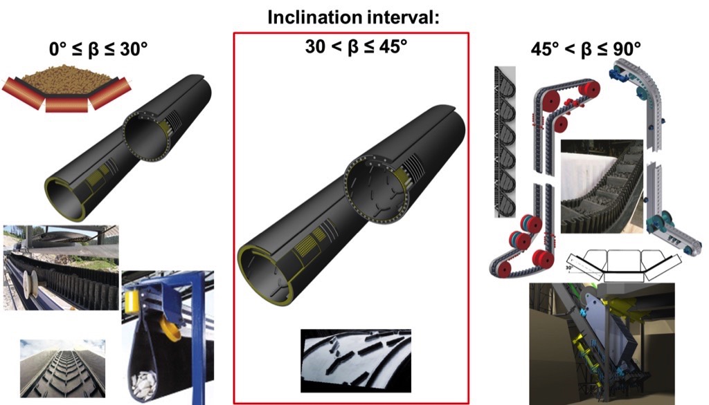
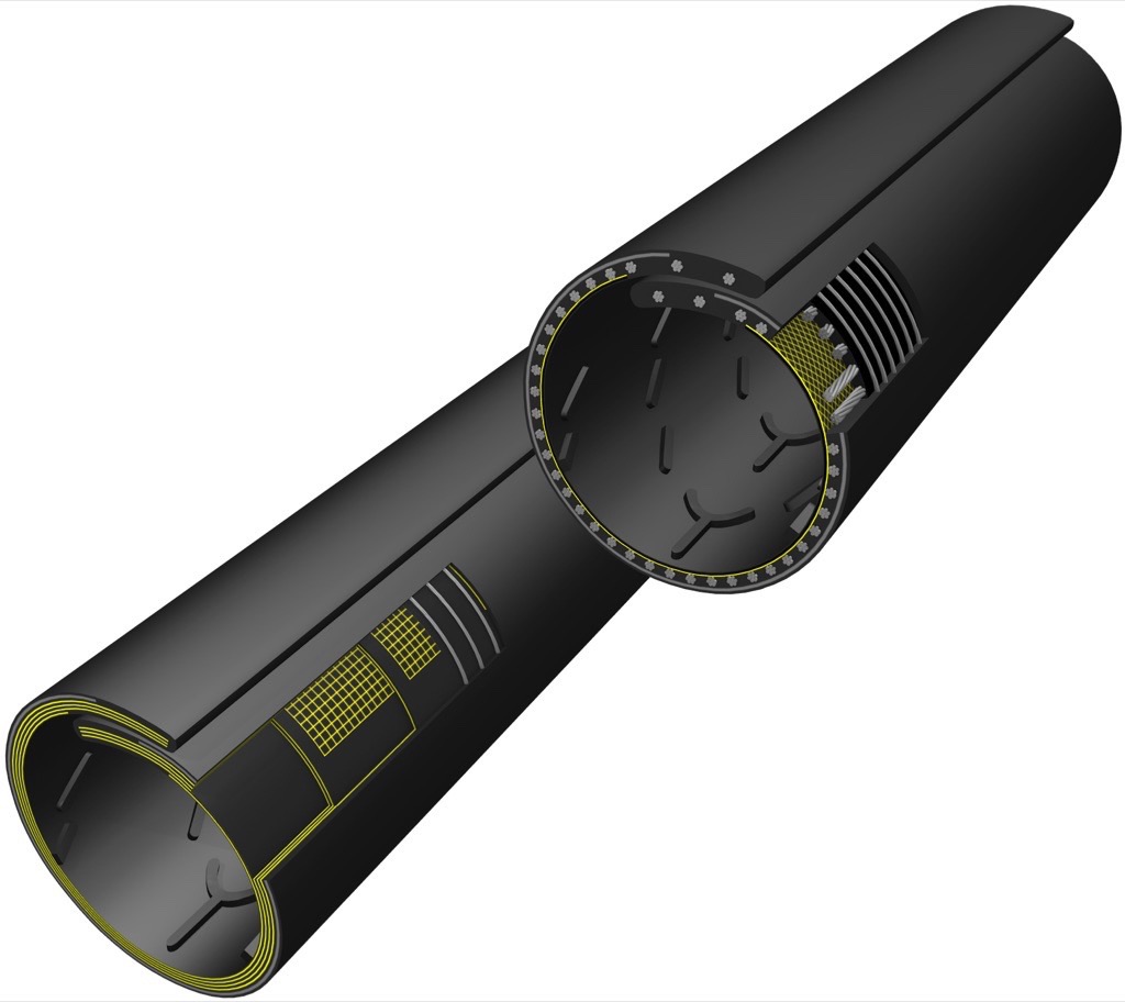
Although troughed belt systems can also be used in hard rock open pit mines with steeper overall slope angles >30°, they require relatively long conveying routes out of the open pit mine.The ever decreasing ore content in many of the world’s deposits means that more and more overburden has to be carried away in order to recover a certain quantity of minerals. The Thyssenkrupp integrated skip conveying and crushing system allows uncrushed run-of-mine to be lifted along the shortest route out of the pit with overall slope angles of 45° to 90° [1] (Fig. 2, bottom right). If the material has been crushed in advance, the Flexowell or Pocketlift systems from Contitech are also suitable here (Fig. 2,top right).The Chevron-Megapipe conveyor is now a pipe belt conveyor with performance data that has never been achieved before for gradability and conveying capacity. It is fed by a primary crushing stage located in the area around the feeding station, and is equipped with a pipe belt with an outer diameter of (DA = 780…900 mm) with a ribbed carrying side cover. In the area around the belt width where the Chevron ribbing has been applied, chevron cleats continuously cover the belt’s entire area lengthwise (except the overlapping area and the areas adjacent to the overlapping area, as shown in Fig. 1).The ribbing of the carrying side cover can feature both a different pattern (fishbone, chevron cleat, etc.) as well as different cleat heights and thicknesses. In general, the cleat height has an interval of 10 to 50 mm, but can also be larger if necessary. The chevron cleats are arranged continuously lengthwise, and this ensures a better grip between the conveyor belt and the material.When the Megapipe is rolled up out of the troughed state and into the tube state in the material feeding area, the material in the enclosed belt is compacted. This causes the material’s internal friction to rise. In turn, the increased internal friction and the high wall friction coefficient of the bulk material in a Chevron-Megapipe positively interact with each other and, consequently, the friction-locked material transportation with a significantly higher inclination comparing to standard belts takes place.When the belt was being developed, the advantages of Megapipe technology were combined with those of ribbed belts (chevron cleat belts) and of high-strength belts (St10000 technology). High-strength ribbed pipe belts with an outer diameter of up to 900 mm and nominal strengths of up to 9500 N/mm facilitate the totally enclosed, curve-friendly transportation of large mass flows of up to 9500 m3/h and grain sizes of up to 350 mm across overall slope angles of 30° to 45° and open pit mine depths of several hundred meters after primary crushing.The Chevron-Megapipe conveyor occupies a niche position between flat or slightly inclined conveyance methods with angles of inclination of 0° to 30° and steep-angle conveyance methods for transporting material at angles of inclination of 45° to 90°. Due to its compact design, environmental friendliness, and high industrial safety thanks to the totally enclosed material conveyance in the pipe belt, a Chevron-Megapipe conveyor can be used both for open pit mining (Fig 3, l.) as well as for underground operations.
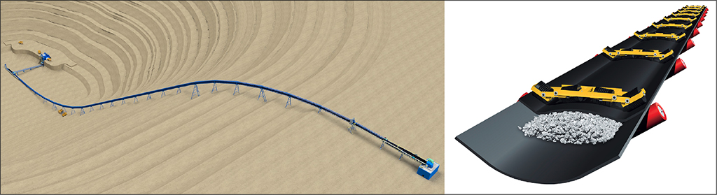
A further alternative conveyance method, that is also suitable for the angle of inclination of 30° to 45°, is a sandwich belt conveyor [2,3]. In this, the conveyor cross-section is formed by two conveyor belts lying on top of each other (Fig. 3, r.). However, when used for deep mines and rough-grained material, this conveyance method has the following decisive cost and system disadvantages compared to a Chevron-Megapipe conveyor:
- The conveyor system consists of two fully-fledged belt conveyors with belts lying on top of one another with all the usual components; the cover belt must be motor-driven in addition to the bottom belt in the case of deeper mines.
- The structure of a pressing roller station of sandwich conveyors is often very complex. A small distance between the pressing roller stations is generally selected in order to achieve an even pressing effect onto the material conveyed with sandwich belts.
- Using sandwich belt conveyors for coarse mining bulk solids is problematic. The material conveyed must in this case be crushed in advance in two crushing stages in open pit mining. By contrast, when a Chevron-Megapipe conveyor is used, one single upstream primary crushing stage is necessary.
| A Note from the Editor | |
| In the above evaluation, the authors of the article refer more or less directly to the third party solution. We therefore consider it appropriate to refer at this point to the article "High Angle Conveying: The Vital (missing) Link to IPCC Systems - 2017", in which the author Joseph A. Dos Santos, developer of the DSI Snake Sandwich Conveyor, also discusses the points raised here from his point of view. | |
Chevron-Megapipe Conveyor
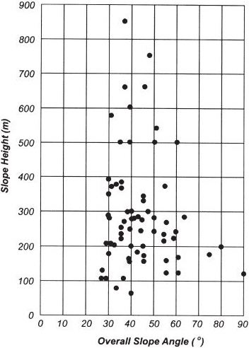
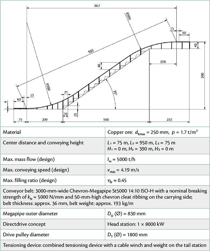
Fig. 4 provides an overview of the ratio of depths and overall slope angles for typical open pit mines based on practical experience, dated August 2003 [4]. Nowadays, modern mines exceed the depth limit of 1000 m, and achieve slope angles of up to 75°. This means that the conveyor belts must have high nominal breaking strengths when belt conveyor systems are used. The diagram shows that most of the world’s mines have embankments with angles between 30° and 50° and are between 100 m and 400 m in depth.For a feasibility study, the following parameters (typical in open pit mining) were therefore selected for the steep-angle conveying of ore or overburden (Table 1):
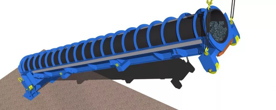
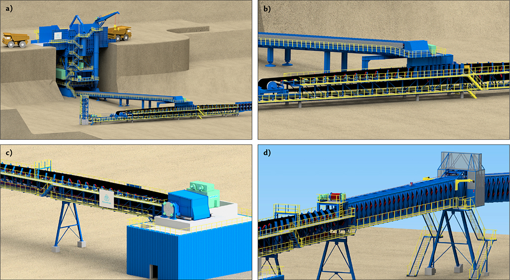
The Chevron-Megapipe conveyor follows the embankment in the form of a vertical S-curve along the shortest route out of the open pit mine. In the bottom excavation area, trucks shuttle the material from the recovery point to a gyratory crusher (Fig. 5a). The primary crushed material is transported from the gyratory crusher to the Chevron-Megapipe conveyor by a short discharge belt, and transferred onto the Megapipe conveyor via a specially designed chute (Fig. 5b). The conveyor belt is driven by Directdrives (Fig. 5c) at the head station that is located at the pit rim. Finally, the material is transferred from the Chevron-Megapipe conveyor to a troughed belt system for further transport (overburden and ore can be handled selectively, if necessary). Necessary maintenance work along the conveyor route can be performed by a service cab that can be moved along the conveyor route by means of a winch drive. (Fig. 5d).
DirectDrive System with Single-Pulley Drive
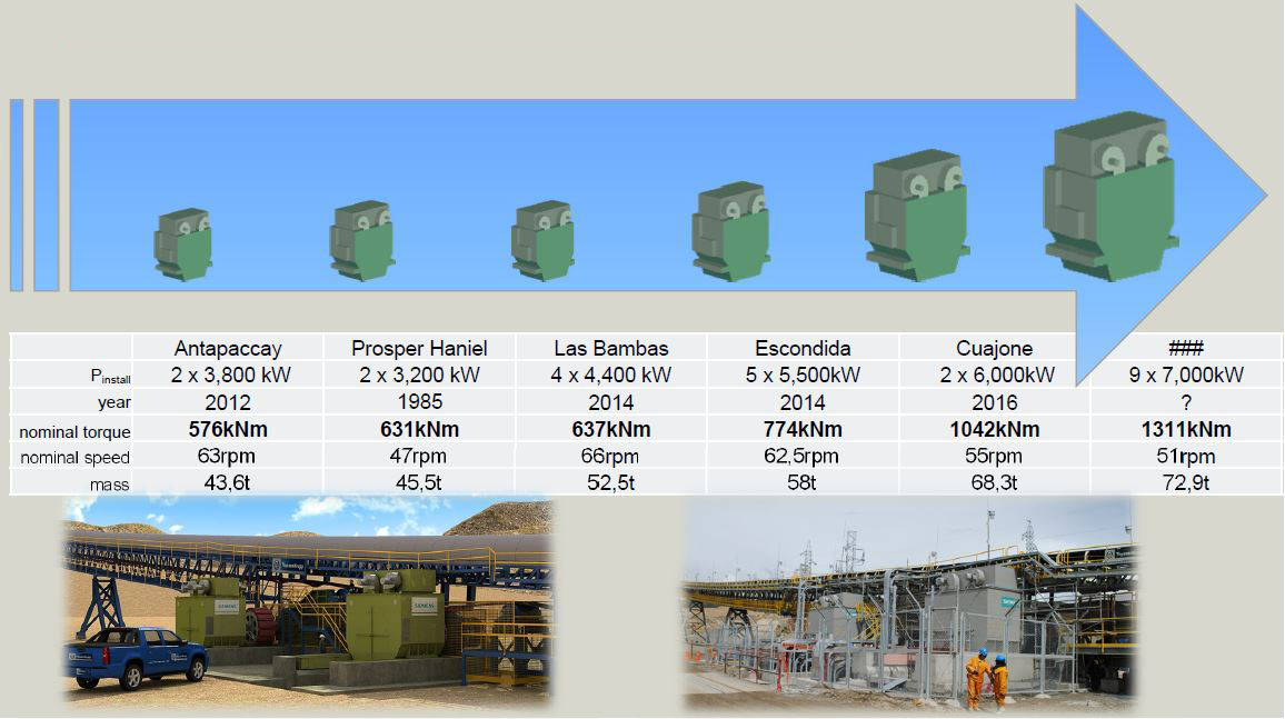
As the name Directdrive implies, the drive power required for this application is transmitted to the drive pulley directly without a gearbox instead of using a multiple gearbox / drive system configuration. The main components in this drive configuration are a multi-pole, slow-running synchronous motor which is powered by a cyclo converter or a voltage source converter.This technology is the first step in meeting the requirements of the global mining industry with regard to higher transport performance without increasing the complexity of the conveyor drive technology. A Directdrive can replace 2, 3, or 4 conventional drives, as required. The use of Directdrives in the raw material industry is nothing new. This technology has been used for decades in hoisting plants (e.g. mine winders) where a high degree of safety is a must for people and the material conveyed. Further applications include Directdrives for bucket-chain excavators, draglines, mills, and pumps.Around five years ago, Siemens and Thyssenkrupp recognized this trend, and together developed a Directdrive for high-performance, conventional belt conveyors on the basis of the “Bandberg Prosper” downhill belt conveyor, which they had built together already in 1985. This conveyor is an underground conveyor that is 3.8 km in length and rises around 800 meters, used at RAG Prosper-Haniel.Thanks to the simple and robust mechanical structure, and the integration of the drive pulley and motor to the Directdrive in combination with state of the art converter technology and with the well proven control unit, a drive solution was created that facilitates cost-effective operation of large belt conveyors. It fulfils the demand of the mining industry to realize large conveyor capacities as center distances and angles of inclination become larger and larger. The reference list in Fig. 6 underlines this trend very clearly.
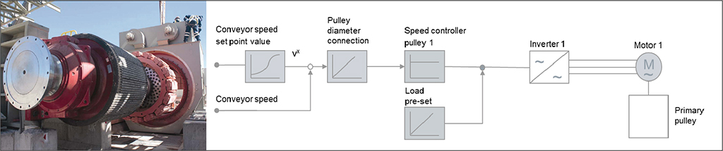
The Directdrive is also the ideal drive for the Chevron-Megapipe belt conveyor, the of which is intended for angles of inclination of 30° to 45°. Only one drive pulley can be used because of the ribbed conveyor belt. For this reason, the drive must provide the entire drive power – consisting of an acceleration component, the steady-state component, which is made up of the load, friction, and, in this case, a considerable elevating component – on just one driven pulley.In the family of three phase induction motors, and particularly in slow-running and bearingless applications, the synchronous motor has established itself as a robust and reliable element. This is thanks to the simple and robust stator structure, comparable to the asynchronous motor. Unlike the asynchronous motor, which requires an air gap as small as possible, the synchronous motor is able to operate with a much larger air gap with no deterioration in the power factor or efficiency. With the asynchronous motor, the excitation power required in the rotor is induced by the stator winding via the air gap in the rotor; the level of excitation power required is among other also a function of the air gap. By contrast, in the synchronous motor, the excitation current is supplied directly in the rotor by means of slip rings; this current is equal to only a few percent of the stator current compared to asynchronous motors. In addition, the synchronous motor’s larger air gap reduces the stiffness requirements to be met by the mechanical components, in particular the pulley shaft.The complete drive train (Fig. 7, l.), consists of the flange for the disk brake, the first bearing, the pulley, the second bearing, the rotor flange equipped with the rotor, and the stator. The “Belt Conveyor Technology Controller” control system developed specially for belt conveyors (Fig. 7, r.) facilitates jerk-free starting.
Determining the Maximum Possible Inclination Angle using DEM-FEM-Analysis
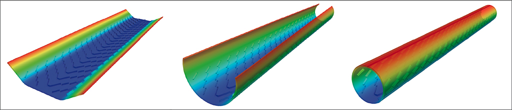
The maximum possible angle of incline is the angle at which a relative movement against the direction of conveyance starts for large, irregularly-shaped grains of material. The theoretical examination was performed taking two different heights of chevron cleat ribbings into consideration: 15 mm and 50 mm. To analyze the material behavior, the parameters of the feasibility study in Chapter 2 were taken and two different degrees of material filling used as the basis, i.e. in the normal operating state (belt is continuously loaded along its entire length) and during discharging so that behavior during deactivation and empty running could also be recorded. The maximum angle of incline of a conveyor belt depends on the interaction between the wall friction coefficient of the rubber cover / bulk material, inner friction angle or angle of repose of the bulk material, the stress condition in the bulk material (compression / loosening), and the grain size distribution (inner particle wedging in the bulk material body).For the analysis, it was necessary to take the behavior of the coarse material in the flat-to-trough section into consideration in order to facilitate a realistic tension distribution in the bulk material. To examine the material’s behavior during a specified deformation of the conveyor belt, it was necessary to conduct a coupled FEM-DEM simulation. The FEM simulations were important in order to map the deformation of a belt section during the flat-to-trough procedure from flat, via a 35° trough, to the ideal circular shape (Fig. 8). With the DEM, the interaction between the bulk material behavior and the conveyor belt was simulated.
The bulk material feed (particle generation) took place with a belt trough of 35°. The bulk material particles are shown in the form of clumps or multispheres, i.e. conglomerates consisting of ball-shaped particles (Fig. 9, l. and ctr.) thus allowing to take a realistic irregular grain size into consideration in the DEM simulation.
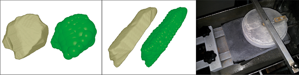
The bulk material properties were identified on the basis of a material sample, and verified with the DEM model of the material.The wall friction coefficients between a copper ore sample (dK < 2.5 mm) and a natural rubber cover (rubber grade “ISO-H”) were calculated at +20°C and -30°C (after 24 hours in a cooling chamber) with the Jenike shear cell (Fig. 9, r.), and showed that the wall friction coefficient is almost independent of the temperature:
- μW = 0.57 or φW = 29.7° at a temperature of +20°C
- μW = 0.61 or φW = 31.4° at a temperature of -30°C
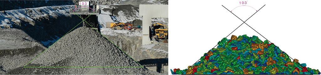
The selection of Coulomb friction μP = 0.8 and rotation friction μR = 0.5 for the particles in the DEM model of the copper ore resulted in the angle of surcharge of φb,stat = 38.5°, which matched the real-life situation very well (Fig. 10).
With the subsequent flat-to-trough transition (for the troughed belt) and with the rolling in (for Megapipe), the stress condition in the bulk material will change. Once the flat-to-trough transition and roll-in procedure had been completed, the angle of incline was adjusted across the global gravitation vector until a large part of the enclosed bulk material slid down.In a second step, the simulation was repeated, but now when only half the belt length was loaded. The goal of these simulations was to analyze the residual emptying in the inclined part of a system. With a lower degree of fill, the belt loses its clamping action on the bulk material in some extent, and the material is more likely to slide. The simulation runs clarified that the ribbing of a Megapipe prevents the material from sliding back, and the value of the critical angle of incline for a complete, automatic residual emptying (running the conveyor empty) was calculated.Fig. 11 shows the residual emptying behavior of a conventional 35°-troughed belt with and without 50-mm-high chevron cleat ribbing in the DEM-FEM model.
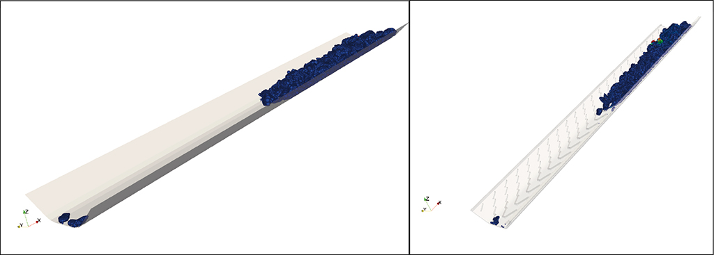
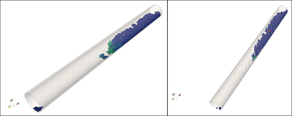
In the case of a smooth troughed belt with a 35°-troughing angle (Fig. 11, l.), the material starts to slide back at the angle of inclination of 22°. If the same belt has a 50-mm-high chevron cleat, the critical angle of incline is 37° (Fig. 11, r). Similar behavior was observed in DEM-FEM simulations of Megapipe with and without chevron cleat ribbing (height of 50 mm). The critical angle of incline was 29° (Fig. 12, l.) for a smooth Megapipe and 46° for a Chevron-Megapipe with a 50-mm-high chevron cleat (Fig. 12, r.).
A summary of the results of the DEM-FEM simulations is given in Fig. 13. This shows that the belt shape (troughed belt or pipe belt) and the height of the ribbing (0 mm, 15 mm, and 50 mm) have a decisive influence on a system’s conveyance capacity and max. angle of incline.
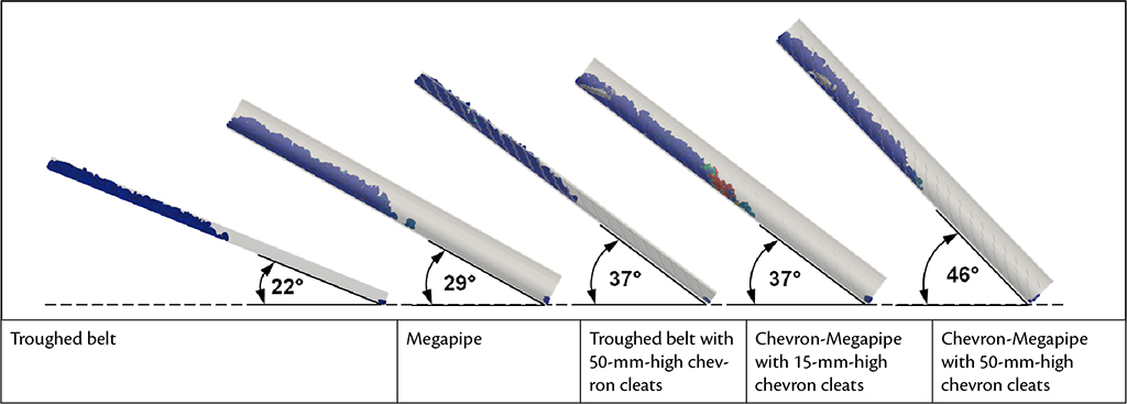
If we compare the results of the DEM-FEM simulations for troughed belts with and without ribbing as well as for smooth pipe belts with ContiTech findings from practice [5], it becomes clear that the max. angle of incline calculated with DEM-FEM simulations is realistic for the above-mentioned belts.With the goal of checking all results from DEM-FEM simulations against reality, the development team is currently setting up a test rig (Fig. 14). In particular, this includes the impact of dynamic effects caused by the belt running across the idler stations as well as the effects of different chevron ribbings, conveying materials and properties (moist / dry), granulations, etc. The time at which sliding starts from a relevant inclination for the coarse bulk material compared to fine-grained materials in commercially-available pipe belt conveyors is of particular interest here.
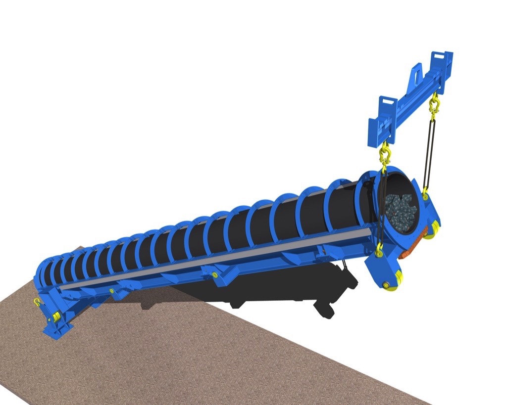
In the test rig, a Megapipe belt piece 10 m in length in the original diameter with and without chevron is placed into a supporting frame, filled with bulk material conveyed, and closed to form a pipe belt. A crane then lifts the supporting frame on one side until the material starts sliding. Vibrations are imposed to the material bed via pneumatic shakers in order to emulate the dynamic stimuli that idler stations produce on a running belt. Since the test rig pipe belt is not scaled down in diameter, a scaling down of the material sample conveyed can also be avoided. Thus, tests with real material samples from open pit mines can be conducted in the Megapipe test rig.
Tests on the Chevron-Megapipe Belt Sample
The goal of the tests was to clarify whether the chevron ribbing influences the transverse stiffness and roll-in behavior of the Megapipe. To this end, an existing sample with a 50-mm-high and 32-mm-wide (H50 x B32) chevron cleats was used to evaluate the form forces and pipe shape on the hexagonal test rig (Fig. 15, upper) in the Contitech technical center. The sample’s form forces (Fn,1…Fn,6) measured after 23h were then compared with the form forces of an identical unribbed Megapipe sample.
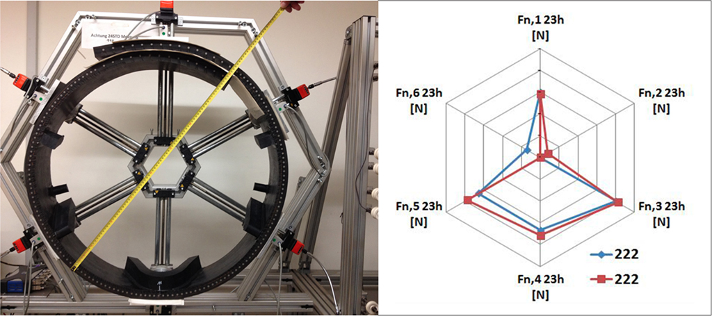
Fig. 15 (upper) shows impeccable roll-in behavior and safe closing of the overlapping area in the Chevron-Megapipe. If we use the spider diagram (Fig. 15, lower) to compare the form forces (Fn,1…Fn,6) of an identical MegaPipe with and without chevron cleat ribbing as measured in the hexagonal test rig, it becomes clear that the chevron cleat ribbing does not have a major influence on the transverse stiffness.
Summary
In the present article, the innovative technology of the Chevron-Megapipe as well as the initial findings from theoretical examinations of the conveyance behavior of steep-angle conveyor belting have been described in discharging and nominal load mode.Some of the findings of the DEM-FEM simulations for a troughed belt and a Megapipe with and without a chevron cleat-ribbed carrying side cover were verified. To further safeguard the theoretical findings from DEM-FEM simulations, a Megapipe test rig is being built as the research project progresses. The roll-in behavior as well as the transverse stiffness of a Chevron-Megapipe were examined on the hexagonal test rig.Initial project-related calculations comparing capital expenditure and operating costs of the new system with conventional transport technology (CAPEX/OPEX analyses) in ore extraction countries were executed. The findings clearly show that the use of the Chevron-Megapipe technology in combination with a pre-crushing stage compared to conventional heavy-duty transport or even normal troughed belt conveyors at angles of incline between 30° and 45° is profitable.
References:
- Wolpers, F.: Skip-Conveying in Opencast Mines - TKF’s Technology Approach to Optimize the Cost and Energy Efficiency in Hard Rock Mines; Conference BulkSolids Europe 2012; Berlin; Germany.
- Dilefeld, M.: “Berechnung und Auslegung von Deckbandförderern” [Calculating and Designing Sandwich Belt Conveyors]; Fachtagung Schüttgutfördertechnik 1996 [Expert Conference on Bulk Materials Conveyor Technology], Otto-von-Guericke University of Magdeburg.
- Stanisic Z., Dos Santos J.A.: In&Pit Crushing and High Angle Conveying at Copper Mine Majdanpek; bulk solids handling Vol. 17 (1997) No. 1, pp. 85-89
- Stacey T.R., Y. Xianbin, R. Armstrong, and G.J. Keyter: New slope stability considerations for deep open pit mines; The Journal of The South African Institute of Mining and Metallurgy, JULY/AUGUST 2003
- ContiTech brochure “Conveyor Belts – System Design Calculations”
| About the Authors | |
| Dr.-Ing. Andrey MinkinContiTech CBG, Germany | |
| Dr. Peter Börstingthyssenkrupp Industrial Solutions, Germany | |
| Dipl.-Ing. Norbert BeckerProcess Industries & Drives Division,Siemens AG, Germany |
■

