
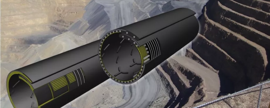
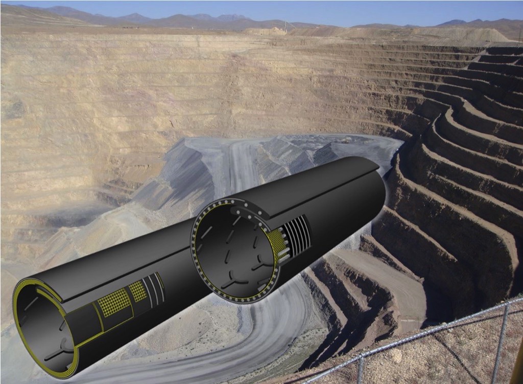
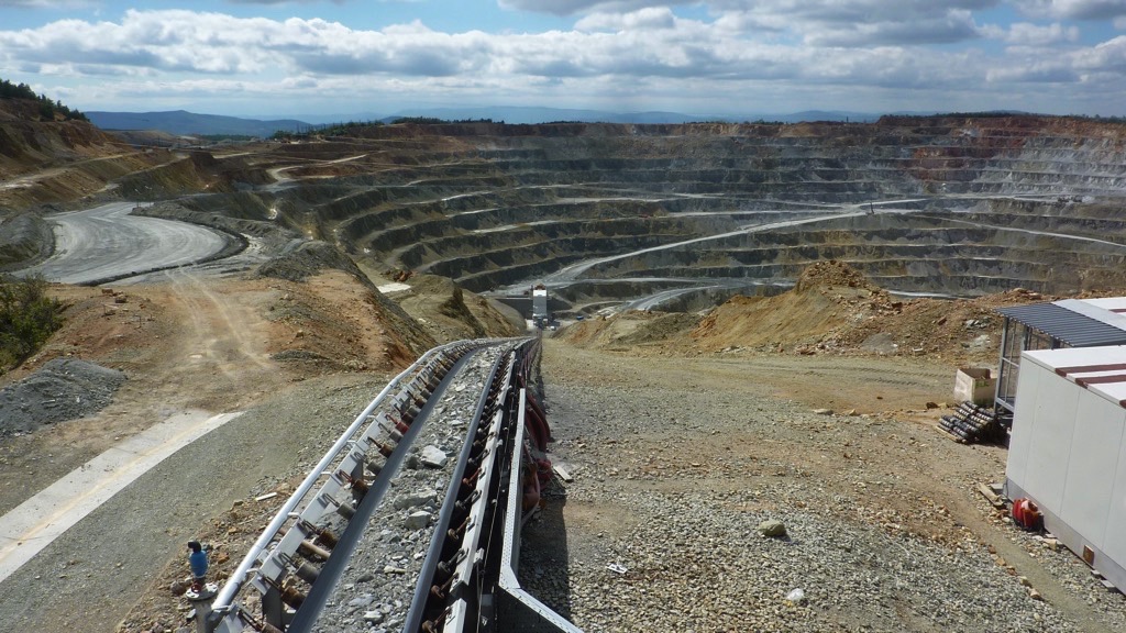
(From the archive of "bulk solids handling", article published in Vol. 37 (2017) No. 2, © 2017 bulk-online.com)In 2013, Thyssenkrupp, Siemens and Contitech established a consortium for developing and marketing an innovative steep conveying concept for opencast mining operations. In the conveying concept, a high-performance conveyor belt takes primary crushed ore or rock overburden from an upstream primary crusher at the base of the opencast mine and conveys the material up the steep embankment of the opencast mine and directly out of the mine.
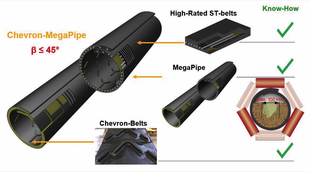
The “MegaPipe” has been subjected to interim testing at the Thyssenkrupp Industrial Solutions research center in Germany with respect to critical conveying angles and wear resistance when coarse and sharp-edged conveying material is used. The Megapipe is fitted with wear-resistant and impact-resistant chevron profiles to enable the efficient conveying of ores and rock overburden over embankments with angles of elevation of up to around 45°. Commercially available deep trough belts with appropriate profiles are also suitable for angles of elevation of up to 30°. The two new system designs can help to significantly reduce conventional heavy-duty motor traffic (trucks or rail) and the resulting high operating costs in surface mines.
1. Profiled Belts for steep Conveying
The Chevron-Megapipe conveyor is a continuously conveying pipe belt conveyor equipped with a pipe belt with the ribbed carrying side (top) cover for an outer diameter of Do = 780 to 900 mm.The pipe belt [1] combines the three most important technical innovations in conveyor belt technology from the last five years: high-strength steel cord belts with a very high dynamic splice efficiency based on the ST 10 000 technology, the corresponding transverse rigidity to hold the Megapipe in a pipe shape, and the solid impact- and wear-resistant chevron cleat-ribbed tread profiles for steep conveying in opencast mines (Fig. 2).
The conveyor only requires a pre-crushing stage in a primary crusher to prepare the ore or rock overburden and it enables enclosed transportation, with vertical and horizontal curves, of large mass flows of up to 6000 m3/h at a maximum conveying speed of approx. 4 m/s (787 ft/min), and a maximum grain size of up to 350 mm, over embankments with angles of elevation of up to 45° and opencast mine depths of up to 700 m. At a realistic annual plant operational availability of 8322 hours, this results in an annual conveying capacity of approximately 50 million m3.The conveying and functional principle of the chevron-pipe conveyor and the initial findings of a feasibility study for a 350 m deep surface mine with a conveying capacity of 5000 metric t/h were described previously in detail in [2].For angles of elevation of up to 30° and non-cohesive/coarse bulk material, a profiled deep-trough belt can also be used as a steep conveyor. The conveyor system is then fitted with a deep trough belt with solid impact- and wear-resistant chevron cleat ribs. The conveyor belt combines the benefits of high-strength steel cord belts, transverse reinforcement based on Barrier technology, and the solid chevron cleat ribs (Fig. 3).
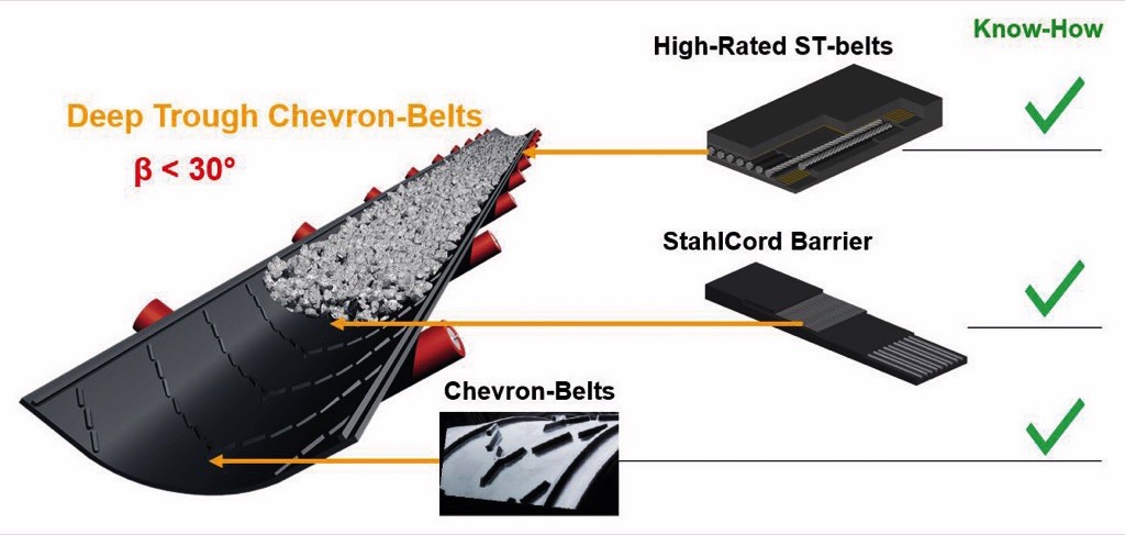
The Barrier steel transverse reinforcement is in the carrying-side cover plate of the belt, and ensures up to three times the impact strength compared to a conventional conveyor belt [3]. The deep trough belt can be produced in widths up to 3200 mm and a maximum nominal strength of 10 000 N/mm. At a slope angle of 30° and a maximum conveying speed of approx. 2.1 m/s (413 ft/min), this belt system can achieve volume flows of up to 12 000 m3/h or an annual conveying capacity of about 100 million m3 per year (based on 8322 working-hours/year).
2. Experimental Determination of the Elevation Angle
The aim of the investigation was to determine in experiments the maximum slope angle for conveyor belts with and without 50-mm-high chevron cleat ribs, and to verify these results against theoretical findings determined previously from coupled DEM-FEM simulations [2]. The maximum feasible angle of elevation for this kind of belt system is the angle at which a relative movement against the direction of conveyance starts for large, irregularly-shaped chunks of material.For this purpose, Thyssenkrupp set up a new test rig with control and measuring technology in its research center in Beckum, Germany (Figs. 5a and b). The bulk material used in the trials was primary crushed diabase (uniform grain size distribution with dGmax ≤ 250 mm).
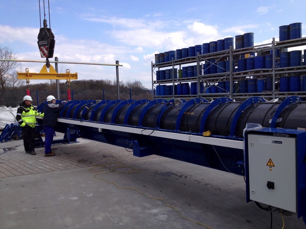 Fig. 5a: Trials on the test rig at the Thyssenkrupp research center.
|
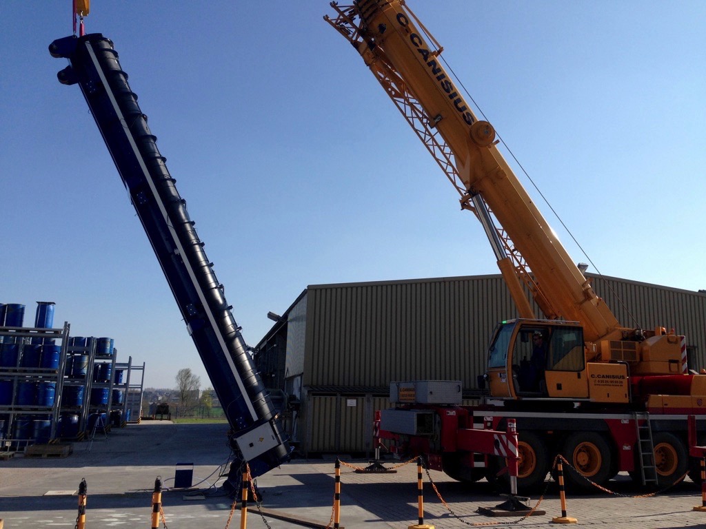 Fig. 5b: Trials on the test rig at the Thyssenkrupp research center.
|
The approximately 10 m long test rig is used to determine the critical slope angle for smooth and profiled, large diameter pipe belts or for deep trough belts, as well as to investigate the behavior of bulk material inside these conveyor belt designs.The tests involved two Contitech pipe belts with diameters of 800 mm, with and without 50-mm-high chevron cleat-ribbed profiling, inserted in a steel carrier pipe with clamping brackets. In order to recreate the dynamic tumbling effects that occur in real pipe belt conveyors when the belt pipe passes through the hexagonal conveyor idler stations, the test rig was fitted with eight pneumatic impact vibrators distributed along the length and circumference of the belt that applied pulsing vibrations to the belt and material bed. A truck-mounted crane slowly and smoothly raised the test rig at one end in order to simulate the slope or the slip angle, resp. In the area of the normal belt overlap in the pipe belt, video cameras with illumination were installed in the longitudinal direction in order to electronically record the start of the bulk material movements depending on the angle of elevation.Fig. 6 shows views from the inside of the approx. 50% filled Chevron-Megapipe with four high-resolution video cameras and with the test rig at the angle of 45.6°: the pipe belt is vibrated by defined impacts at corresponding time intervals, and the first material particles begin to move (camera 4 shows the first four stones at the bottom of the test rig).
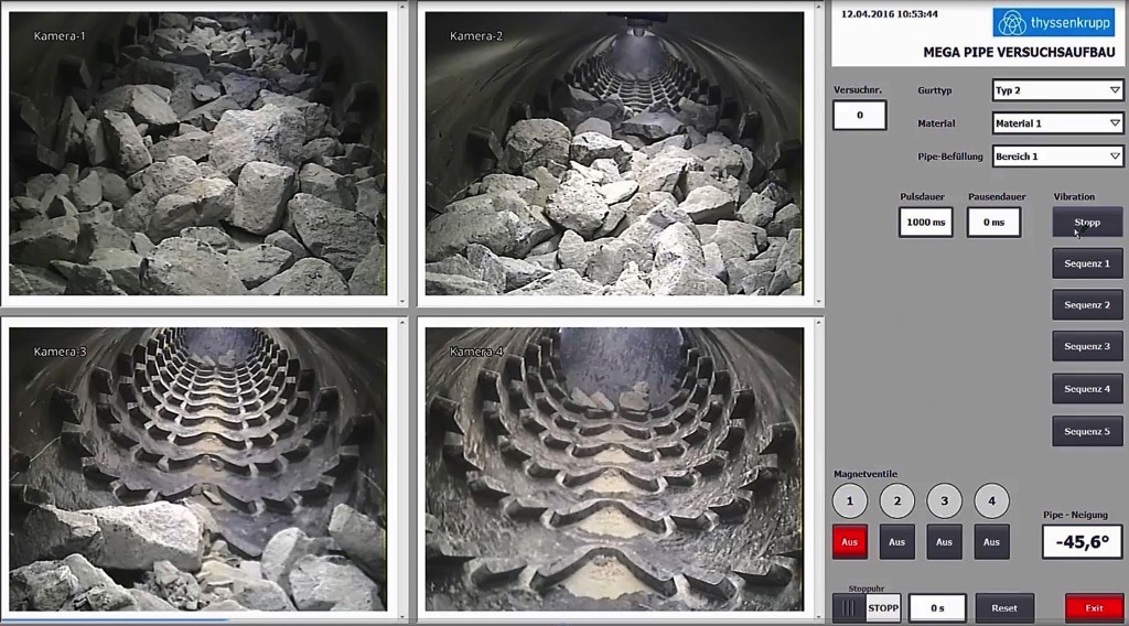
Fig. 7 summarizes the results of the investigation for coarse bulk material in the pipe conveyors, with and without the mentioned chevron cleat ribs for the “critical” case (complete emptying of pipe). Half the test rig was filled for this reason with material to a fill factor of 50% of the cross section. This means that, as in real conveyor operation, there are no supporting and subsequent layers of material present when a pipe conveyor is emptied.
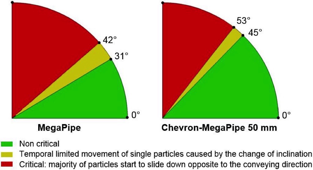
The maximum possible slope angle for a belt system without backward slipping of the material bed depends both on the system parameters (e. g. belt geometry, conveyor speed etc. ) and on the properties of the bulk material. The angle is the result of the interaction between the wall friction coefficient (rubber cover plate/bulk material), inner friction angle of the bulk material (the angle of repose, to simplify), the stress condition in the bulk material (compression/loosening), and finally the grain size distribution (inner particle wedging in the bulk material body). As the bulk material properties of the primary crushed diabase are very similar to the properties of similar coarse-grained bulk material such as ore or rock overburden, the findings of the investigation can also be applied to other, similar primary crushed bulk materials in hard stone opencast mining.If we now compare the results from the current experiments against previously published results from DEM-FEM simulations [2], we can see that the theoretically determined slope angles are almost identical to the values determined in experiments. This close consistency of findings when determining the maximum slope angle confirms that purely theoretical investigations of the slip characteristics should suffice in the future for similar bulk materials and system parameters.
3. Investigating Impactand Cleat Ribs’ Wear-Resistance
Experimental investigations of the impact-strength, bond-strength and wear-resistance of the new chevron cleat ribs on the Contitech impact test rig (Fig. 8a) and in a belt system transfer station in the Oetelshofen limestone opencast mine in Germany (Fig. 8b) were used to determine the expected lifetime of chevron cleat ribs referring to a wear and a profile bond-strength to the belt surface under the extreme opencast mining conditions.
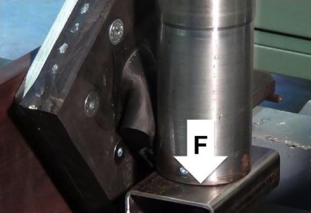 Fig. 8a: Experimental investigations of the impact-strength, bond-strength and wear-resistance of the new chevron cleat ribs on the Contitech impact test rig.
|
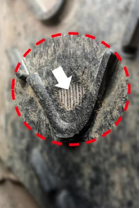 Fig. 8b: Experimental investigations of the impact-strength, bond-strength and wear-resistance of the new chevron cleat ribs in a belt system transfer station in the Oetelshofen limestone opencast mine.
|
The aim was to develop innovative chevron cleat ribs with an optimum profile geometry and to develop a rubber compound that will exhibit especially strong durability under the most severe impact and wear conditions. The bond strength and impact strength of the chevron profiles were investigated under practical and laboratory conditions at the Contitech test facility, by means of impact tests. The required wear-resistance for these profiles was verified using sample belt sections as an impact plate in a material transfer station within the conveying flow of a limestone quarry (Figs. 8a and b).Fig. 8b shows that the newly developed chevron cleat rib exhibits longer durability than the 14-mm-thick upper rubber cover plate of the basic belt 2000 St3150 14:7 DIN-X. The 1026-m-long steep conveyor, the system parameters from [2] and the 14-mm-thick rubber cover plate were used to calculate the durability of the chevron profiles. Taking into account the measured hours of use until the profiles wear in the material transfer station, the theoretical durability of the chevron profiles was calculated as approximately five years or more.
4. DEM-FEM Analysis for a Chevron-Megapipe Loading Point
Due to the fact that, after primary crushing of the raw material, so-called fish-lumps (meaning particles with a length to width ration >3) with edge lengths of up to 400 mm can occur in open cast mining operations and these lumps have to be securely redirected in the loading station (which is generally right-angled) from the crusher outlet belt and onto the pipe conveyor and then embedded into the material flow of the pipe, special structural requirements apply to this task area. Among other tasks, it must be ensured that fish-lumps do not land on the open belt at right angles to the direction of flow so that they do not jam between the conveyor idler stations when the troughed belt is forming into a closed pipe belt (by specially configured finger rollers) and damage the idler stations (Fig. 9).
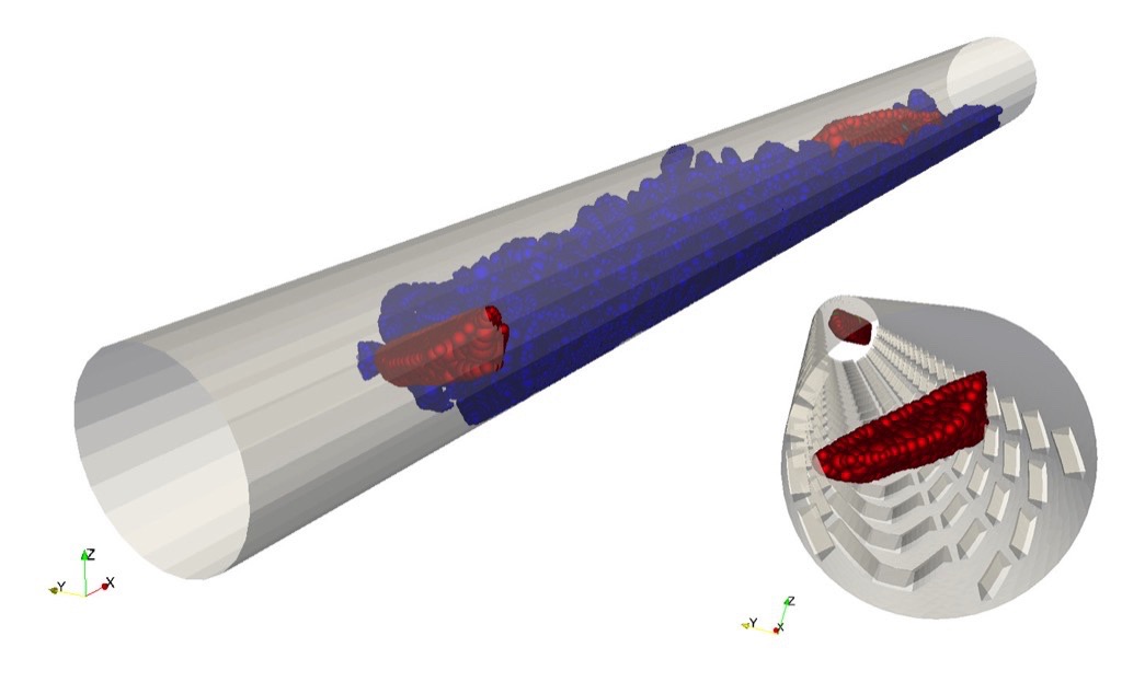
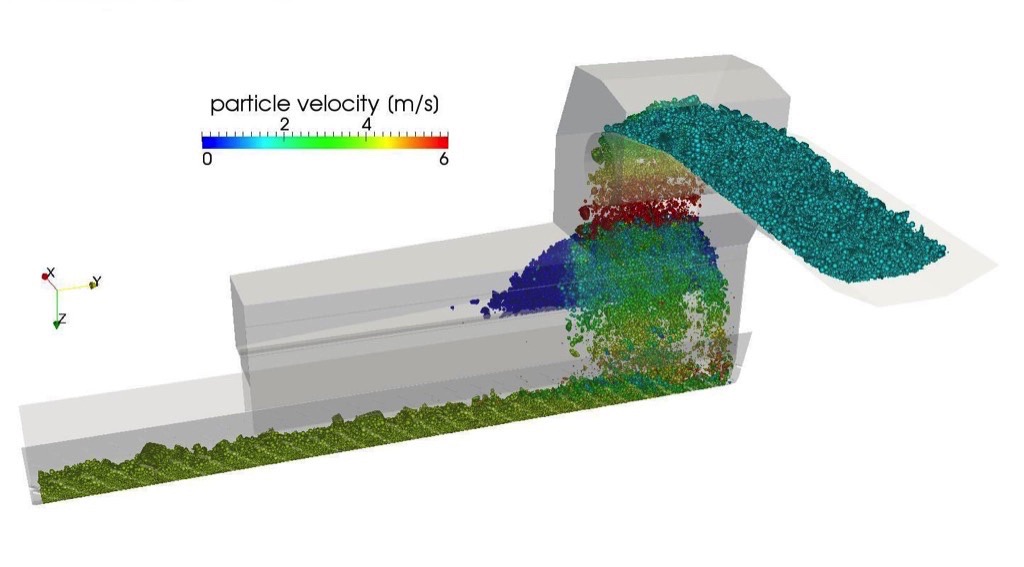
Multiple calculation runs of a coupled DEM-FEM bulk material simulation finally resulted in the optimum design for a loading station.The crushed material from the crusher is transferred via what is known as a rock box to the conveyor belt, which is still U-shaped at this point (Figs. 10 and 11).
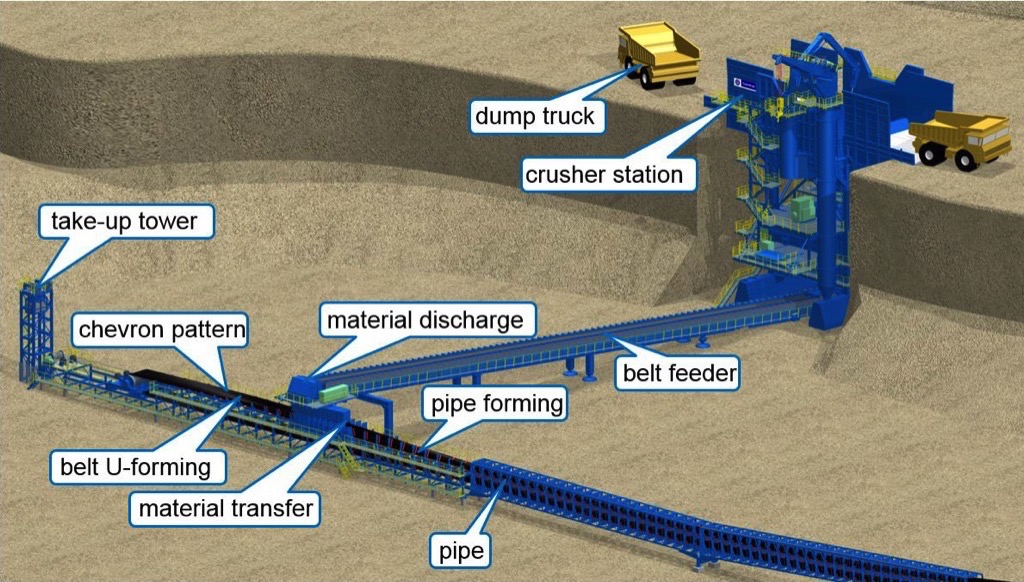
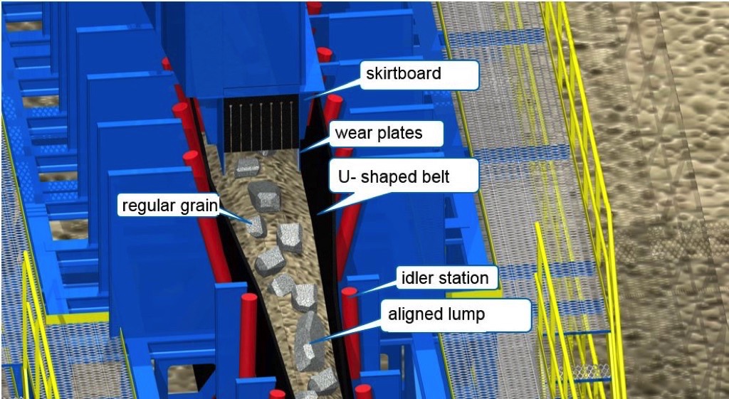
The transfer chute to the Megapipe [4] must be designed so that the material rebounds off a rock box and then falls directly into the U-shaped pipe belt. The width of the U-shaped transfer area already corresponds to the pipe diameter that is to be formed; this ensures there is no further constriction of the clear belt width when the pipe is then formed. The U-shaped loading area is approximately 8 m in length. In this section, the material should settle and the conveying speed should simultaneously increase. Unlike in conventional pipe conveyors with classic trough loading stations, there is hardly any material shifting within the U when the belt is reshaped into its circular cross-section as it passes along the conveying direction.As the results of the DEM-FEM simulations (Fig. 12) show, the length is sufficient to align the lumps in the conveying direction. The material guidance itself is designed to open up in the conveying direction. The clear width of the material guidance is approximately 700 mm at this point, which is sufficient, given the wide flow of the material feed, to allow a material flow of 5000 metric t/h of copper ore (particle size distribution 600...20 mm) without overfilling or blockages.
5. Direct Drive Solutions for the new Transport System
Due to the boundary conditions that must be met for a Chevron-Megapipe conveyor, the right drive solution for this new transport technology is a direct drive. The high conveying capacities and the lifting heights involved require multiple megawatt drive outputs. In addition, the entire drive output has to be transferred to the belt via a single drive pulley because the chevron profiling means that no additional belt redirection using further pulleys is possible..
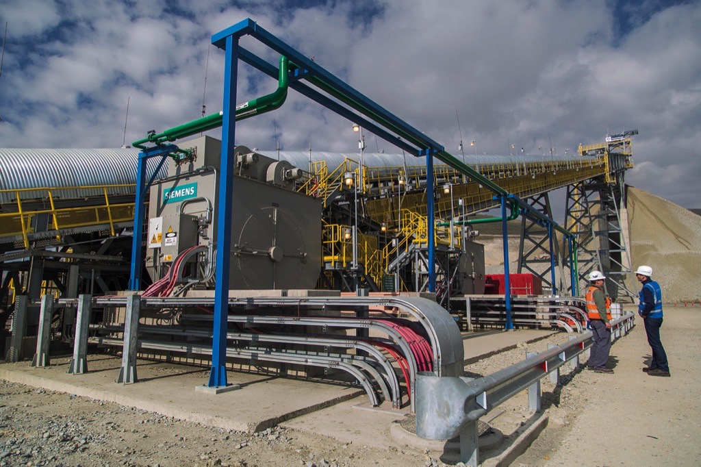
The drive solution developed jointly by Siemens and Thyssenkrupp [5] does not require elastic coupling between the motor and drive pulley and it does not require more than two roller bearings for the entire drive train. This means that very few mechanical components are involved, which increases the efficiency and availability of the drive. This drive solution is already successfully used in many belt conveyor systems with motor outputs of six megawatts.In normal operation, the drive is started up and stopped at defined ramps by means of a frequency converter. These ramps are determined and implemented during commissioning or in a simulation analysis carried out in advance. The drive train is completed by a mechanical brake that is designed as an emergency stop and/or holding brake, depending on the requirements.The direct drive, combined with tried-and-tested control algorithms for belt conveyor drives, enables reliable and lasting operation of the belt conveyor.
6. Cost Comparison Chevron-Megapipe vs. conventional HD-Trucking
The cost-effectiveness of continuous conveying technology in opencast mining is compared to discontinuous transport using heavy-duty traffic involving trucks and rail. Through a primary crusher at the base of the opencast mine, a Megapipe conveyor provides the steep transport at right angles to the opencast mine embankment. Comparison calculations here are based on conveying capacities using heavy-duty trucks and rail in a well-known iron ore surface mine in Eastern Europe.In this opencast mine with the dimensions L ≈ 5000 m × W ≈ 3000 m × H ≈ 480 m, approximately 50 million metric tons of material per year are transported out of the mine by 27 heavy-duty trucks (payload 120 metric tons) and 36 hopper trains (payload 1000 metric tons).Alternatively, using a single Chevron-Megapipe with a diameter of 900 mm and a conveying speed of 4 m/s and a fill factor of approx. 50%, the equivalent annual conveying capacity of 50 million metric tons could be transported with an operational availability of 8322 hours.Utilising an IPCC-system (here with Chevron Megapipe conveying out of the opencast mine) reduces operating, personnel and maintenance costs while simultaneously reducing the mines CO2 footprint.
Summary
This article describes the results of experimental investigations of the conveying characteristics of steep inclined conveying systems, as well as the results of the impact-resistance, bonding-strength and wear-resistance tests of the newly developed chevron cleat ribs.The published findings of the DEM-FEM simulations for a deep trough belt and a Megapipe belt with and without a chevron cleat-ribbed carrying side cover [2] were verified.The Chevron-Megapipe conveyor developed jointly by the consortium enables enclosed steep conveying or primary crushed ore or rock overburden at an angle of elevation of up to approx. 45°. The conveyor therefore enables an important contribution to reducing heavy-duty traffic, CO2 emissions and, as a result, operating costs in surface mining.An 830 mm diameter Chevron-Megapipe prototype was presented to the public for the first time at BAUMA 2016-fair in Munich.
Bibliography:
- Patent no. WO 2014180585 A1 and no. PCT/EP2014/054296: Tubular conveyor belt or pocket conveyor belt having a chevron profile arrangement on the carrying side thereof cross reference to related applications (ContiTech, A. Minkin, 2013)
- Minkin, A., Börsting, P., Becker, N.: Pipe Conveying the next Stage – A new Technology for Steep Incline High Capacity Open Pit Conveying. bulk solids handling Vol. 36 (2016) No. 2/3, pp. 16-23.
- Minkin, A.: Cost Reduction in Belt Conveying. bulk solids handling Vol. 35 (2015) No. 2, pp. 16-23.
- Patent application no. PCT/EP2017/ 053852: Förderanlage zum Fördern von Fördergut [Conveyor system for conveying material] (Thyssenkrupp Industrial Solutions AG, G. Michaeli and F. -M. Wolpers, 2017)
- Patent no. WO 2013/026672 A1: Belt-conveying installation, method for operating the same, and use thereof [Bandförderanlage, Verfahren zu deren Betrieb sowie deren Verwendung] (Siemens AG, 2013)
| About the Authors | |
| Dr.-Ing. Andrey MinkinApplication EngineerContiTech CBG, Germany | |
| Dr.-Ing. Torsten HellmuthProduct Manager Bulk Material HandlingSIEMENS AG, Germany | |
| Prof. Dr.-Ing. Franz-Maria WolpersHead of Mat. Handling Rohrbach and R&D Miningthyssenkrupp Industrial Solutions AG, Germany |
■

