
(From the archive of ”bulk solids handling", article published in Vol. 36 (2016) No. 5 , ©2016 bulk-online.com)The increased demand of transporting material over longer distances at higher capacities with reduced project timelines is pushing designers to think out of the box and apply new technologies. Conveyors are designed with many assumptions varying from friction factors, efficiencies, dynamic effects and the design engineers’ preferences, but seldom is the design verified with actual field results. It is critical that the designer gets performance feedback from the conveyor and field measurements that can be fed back into the original design to improve on the assumptions made.This paper describes an overland conveyor where specific challenges are highlighted during the design and installation of the conveyor. Field measurements were taken and a comparison made between the designed and actual results.
1. System Description
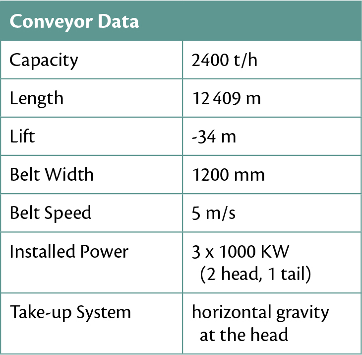
The conveyor is 12.4 km long with a 34 m elevation drop from the tail to head end transporting 2400 tonnes per hour of coal. The basic design summary is listed in Table 1.
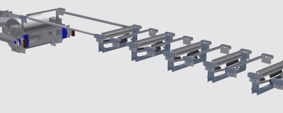
The conveyor is routed along a defined servitude and built on a prepared terrace. This servitude crosses under a national highway and over a rail service. In order to cross these services the conveyor has five horizontal curves with radii of 6000 m of which two are compounded with vertical curves to enable crossing over the rail service.The drive system consists of two drives at the head end and one at the tail end as shown in Fig. 1.

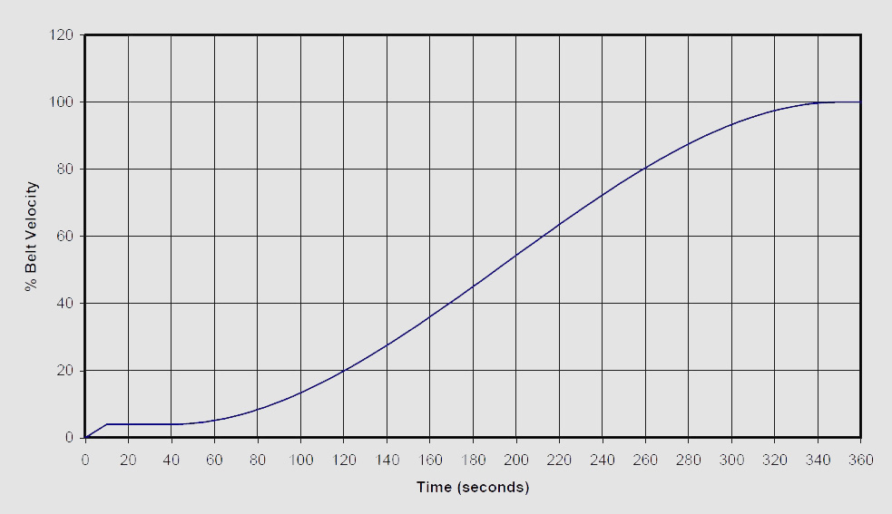
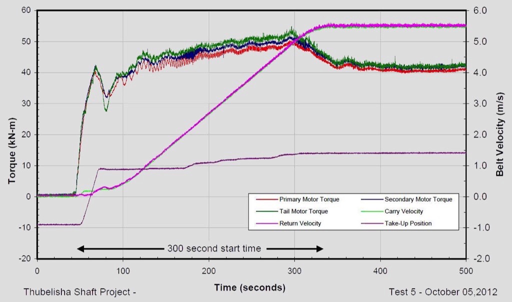
To ensure the dynamic stability of the conveyor under various loading, starting and stopping conditions, two 125 kg∙m2 flywheels are installed at the two head drive units. The start-up control is done by variable frequency drives, and a constant high speed brake installed at the tail drive prevents excessive sag and drift times during emergency stopping conditions. Additionally, the brake also reduces dynamic tension waves induced under emergency stop conditions. The start-up consists of a 10 second pre-tensioning step, where after a constant tension dwell period stabilises belt tensions for 30 seconds. After the 30-second dwell period, the belt is accelerated on a Hermite S-ramp to full speed. Total starting time was specified as 350 seconds (Fig. 2).
Many design iterations were done to optimise the idler configuration and idler spacing, which led to increased power efficiency and reduced costs on the capital investment as well as the operational cost of the conveyor.
2. Design Challenges
With challenging design boundaries, it was decided to highlight specific areas which were deemed important to include in the paper and for other designers to consider.
2.1 Turnovers
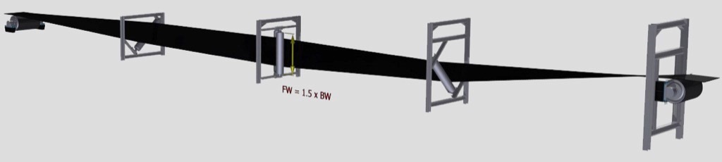
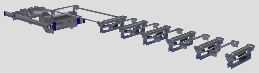
Belt turnovers where specified in the client’s design criteria and, in any event, it is good engineering practice to install them on overland conveyors. Turnovers minimise spillage from the return strand along the length of the conveyor when belt cleaning is not effective or functional. The ecology it is an important factor on a conveyor, as the spillage area is known and can be managed. However if not designed correctly, it could be detrimental to the belt and belt splice life.Various conveyor belt suppliers provide the calculation methodology for the minimum required length in a turnover system. For this conveyor the dynamic analysis was done by an external consultant who specified the turnover lengths at the head and tail at 35 metres and 40 metres [1] respectively.As this conveyor was one of three overland conveyors, with varying turnover lengths, it was decided to use a modular design which could be applied to all three conveyors by placing the support structures at the required spacing for each.The face width of the turnover pulleys was made 1.5 times the belt width which allowed sufficient clearance for the belt to sag at the midpoint during installation, maintenance and low tensions (Fig. 3).
Turnover pulleys were of the dead shaft design to prevent bearing failures on the bottom bearing due to dirt and water build-up as experienced with live shaft pulleys with plummer block arrangements.
2.2 Take-up Length
Due to the horizontal pulley centres being 12.4 km, the required take-up displacement was approximately 26 m which included for permanent elongation, two splice lengths and dynamic displacement. The selected take-up was a horizontal gravity system which meant that the take-up pulley would be able to freely move the total distance. However, the take-up mass was only required to move for the dynamic displacement distance plus the required clearances (Fig. 4).
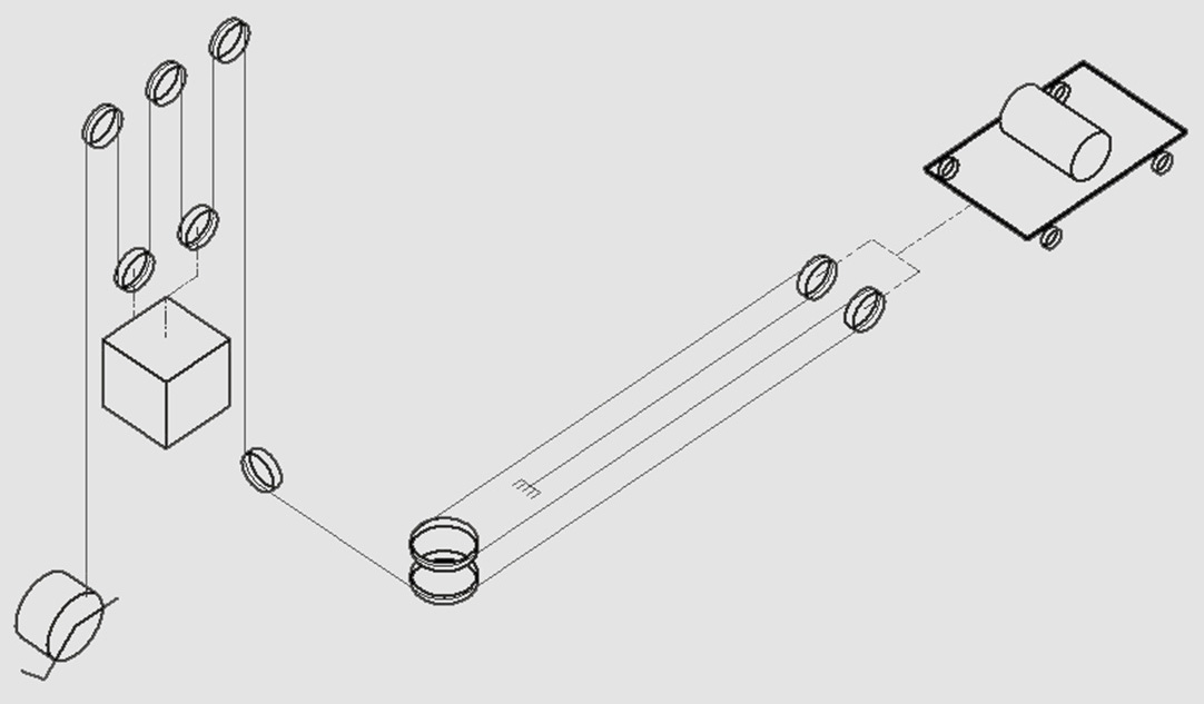
With the horizontal travel requirement of 26 m, belt sag becomes a major problem in the horizontal take-up, and the belt needs to be supported at intervals equating to the maximum allowable sag during dynamic conditions. To be able to support the belt at the required intervals, retractable idlers were installed on trolleys which move with the take-up trolley (Fig. 5).
2.3 Take-up Mass
The T2 belt line tension was 165 kN and a 4:4 reeving ratio was selected, which enabled the use of standard take-up equipment readily available on the market. With a take-up mass of approximately 34 tonnes, the use of steel punchings proved to be uneconomical due to their relative low bulk density and therefore steel plates were utilised, reducing the volumetric requirement of the take-up mass.
2.4 Tail Drive
Designing and installing a tail drive was nothing new, but with the two drive stations being 12.4 km apart it was critical that reliable communication between the drives was guaranteed, as load sharing and control need to match with the design philosophy. This was achieved by successfully installing a dedicated fibre optic communication line between the control units.
2.5 Idler Selection
A vital part of conveyor design is selection of the idlers. This selection becomes more important on overland conveyors where not only the functional selection, but the economic impact of the selection is of significance. For this conveyor, oversized Ø 178 mm series 40 centre roll and Ø 152 mm series 30 wing rolls were selected. This selection was based on the carrying capacity of the belt, idler spacing and installation cost. The oversized centre roll also contributed to less rolling resistance as the belt selected had normal good rubber covers and was not designed for low rolling resistance covers.
3. Execution Challenges
With any design, most parameters are defined or calculated, but can change in an instant during construction. It is important that the construction team communicate any change in the design to the design team as certain changes could negatively affect the design intention and consequently the performance of the system. Some challenges during the project execution which had a significant impact on the design intention are described below.
3.1 Design Terrace
Part of the design scope of work was to determine the conveyor terrace level which was to be constructed by others. The main elements in determining the terrace level were the conveyor centreline, which had to conform to the conveyor’s designed horizontal and vertical curve requirements. The terrace layout with the above requirements was then issued.Due to the length of the conveyor, the terrace was handed over in sections as the construction was completed. Upon receiving the platform for construction of the conveyor, major discrepancies in some areas were identified. Taking the project timeline into consideration, some out of specification areas had to be reworked and others accepted on the basis that they did not impact on the designed vertical curves.
3.2 Installation Tolerances
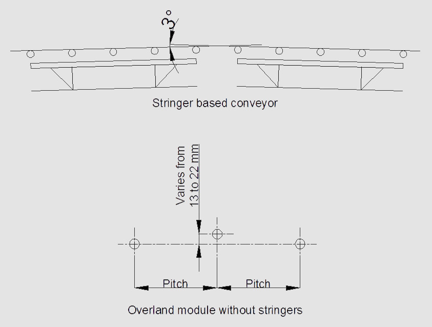
One of the most important aspects impacting on the success of any conveyor is the accuracy of the installation. Adhering to the specified tolerances, accurate alignment of the idlers to the conveyor centreline and assurance that the pulleys are squared to the centreline result in a straight running conveyor belt.What was discovered during the installation of this particular conveyor was that with the increased idler spacing, the normal installation tolerances applicable to stringer based conveyors were too onerous in some instances and too relaxed in other. These were reviewed and adjusted taking into consideration the vertical curve requirements for both concave and convex curves (Fig. 6).
3.3 Drive Problems
During commissioning some issues with vibrations on the drive arrangements were experienced. These vibrations were predominantly present in the flywheel area. After realigning and rebalancing the flywheels and drive arrangement, the problem still persisted.Further investigation and vibration analysis pointed to the origin of the vibration being the couplings which were installed between the motor – flywheel and flywheel – gearbox. High speed gear couplings were originally selected and installed by the gearbox supplier. The mechanical interaction between the gear teeth in the couplings excited unacceptable vibration levels to the extent that the condition monitoring system tripped the system on overall vibration levels above 12 mm/s2. These couplings were replaced by rubber buffer couplings which solved the problem.
4. Field Measurements
Field measurements are an essential part of the commissioning procedure of any long overland conveyor for two principal reasons:
- In order for the designers to verify and optimise theoretical design models specifically relating to frictional values on belting covers such as low rolling resistance (LRR) belting, and also different idler roller configurations and the associated rolling resistances.
- For the end client in terms of verifying specified design parameters.
4.1 Methodology & Test Equipment
Shaft Torque
Shaft torque is perhaps the most important measurement when verifying the design of the conveyor and ensuring that the system is behaving as per the design specifications.The actual torque was measured on the output shaft of the gear reducer of each of the three 1000 kW drives. The shaft torque measurements show the precise input torque during starting and stopping. Thus, any torque spikes, fluctuations, load sharing problems, as well as other anomalies are immediately visible [2].
Belt Velocity
Accurate belt speed measurements are essential in verifying dynamic performance and ensuring the PLC starting and stopping control is functioning properly. Belt speed sensors were installed on the carry strand at the head and tail ends of the conveyor [2].
Take-up Displacement
Take-up position was also measured. The position encoder was placed on a wheel of the moving carriage which is attached to the take-up pulley [2].
Belt Capacity
Material capacity was recorded by two separate 0.5% accuracy weight scales on a preceding conveyor [2].The conveyor was tested under the following loading conditions:
- Empty start and steady state running and stopping
- 1075 t/h – start, running and stopping
- 2340 t/h – start, running and stopping
Empty Start and Stop
The first empty start test revealed that the PLC start time was set to 270 s and not 350 s as specified. The conveyor was, however, dynamically stable during starting and stopping conditions. The measured belt speed was also 5.5 m/s and not 5 m/s as per the orginal design (due to a calibration error with the belt speed sensor (Fig 7)).
Conveyor Start at 1075 t/h
The next test logged was a start-up at 1075 t/h. The conveyor was dynamically stable during the start period with very good load sharing between the tail and two head drives (Fig. 8).
Conveyor Stop and Start at 2340 t/h
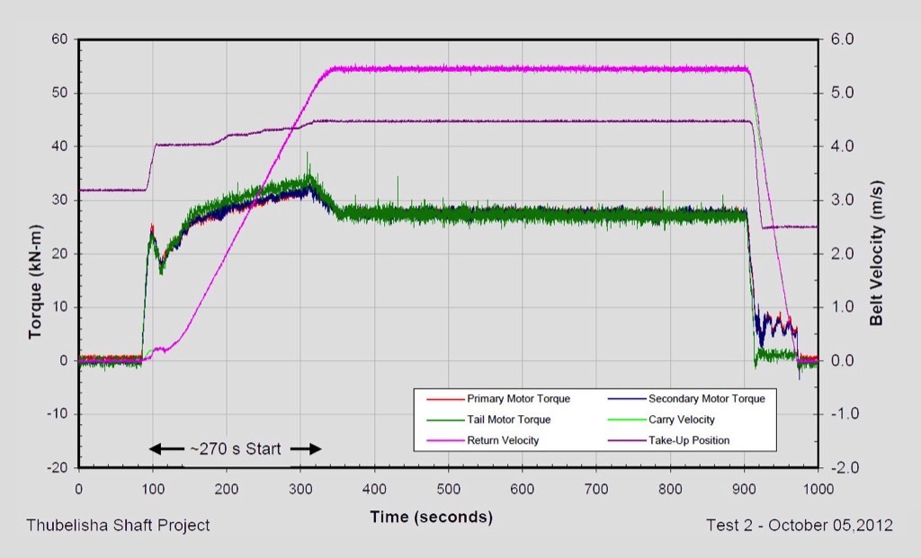
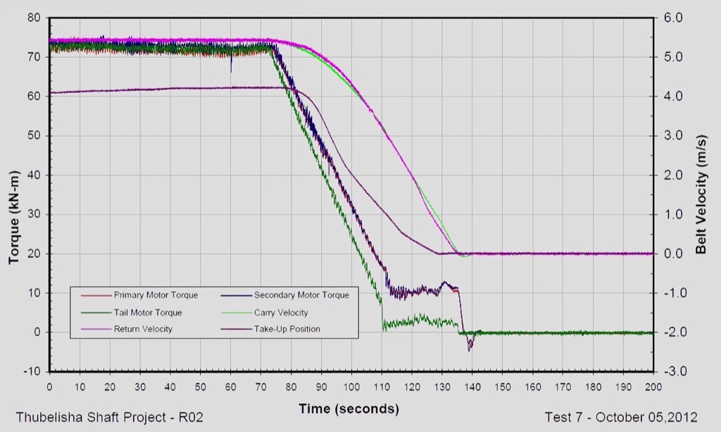
During the next set of tests the start time was increased to the required 350 second duration and the capacity was ramped up close to design capacity. Unfortunately, the downstream conveyors could not handle the design capacity of 2400 t/h and the capacity was ramped up to 2340 t/h for a short duration and stopped. As depicted in Fig. 9, the conveyor was started again at 2340 t/h for a short duration and then stopped, with the latter being presented in Fig. 10 as well.
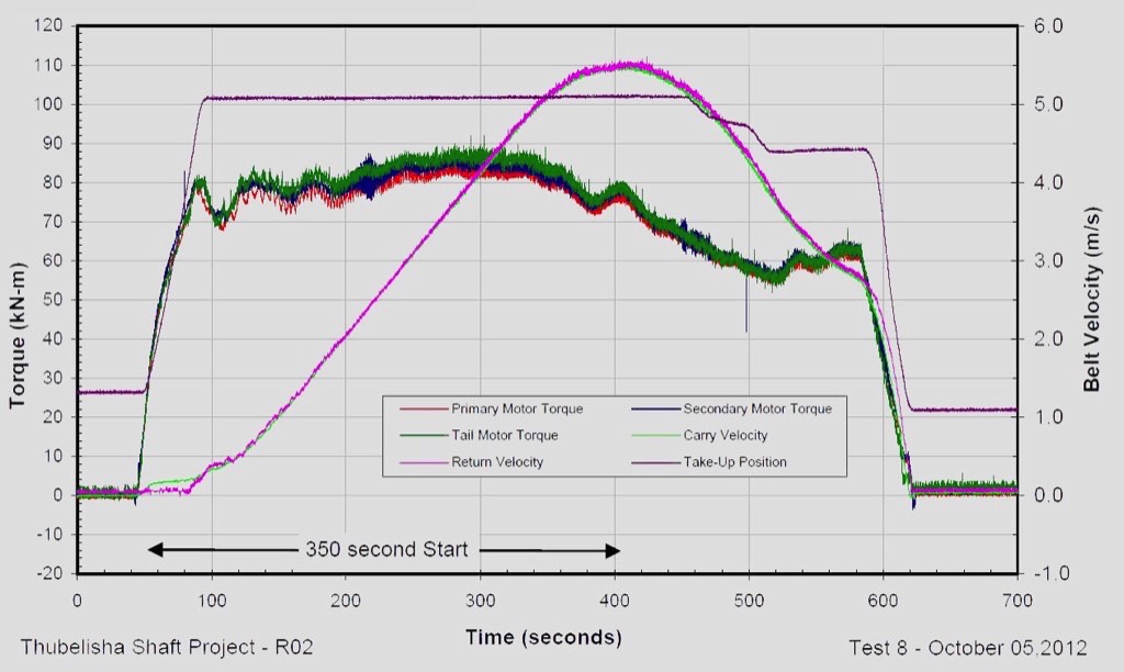
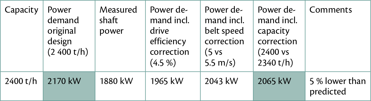
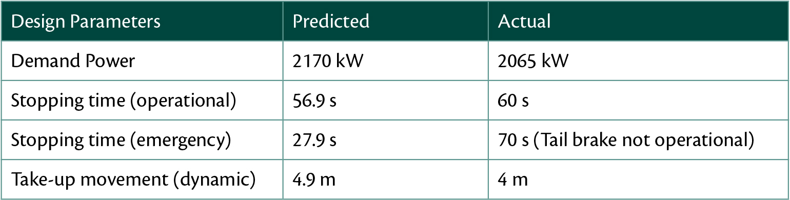
At near full design capacity the overland conveyor showed no indications of any adverse dynamic behaviour during the stop and start conditions.The actual measured shaft power was 1880 kW, which when adjusted for belt speed and capacity, equated to an actual power demand to 2065 kW, 5 % lower than predicted during the original design (Table 2).
A comparison of design data and field measurement results is presented in Table 3.
5. Conclusion
In addition to the many design challenges associated with long overland conveyors such as dynamic behaviour, there are also several site installation challenges which must be adequately addressed to ensure acceptable levels of performance.Field measurements and performance tests are essential to check, verify and improve design models which ultimately leads to improved design predictions and ensures continued development of conveyor systems and in particular, overland conveyors.
Acknowledgement:
This article is based on a presentation of the authors during Belton 18, 5./6. August 2015 in Johannesburg, South Africa.
References:
- Kruse, D., and R. Lemmon: Conveyor Design Report, (2010).
- Kruse, D., and R. Lemmon: Data Acquisition & Field Measurements on CV-OLC-R02, (2012).
| About the Authors | |
| Willem NiemandtEngineering Manager,Sandvik Mining Systems, Rep. of South Africa | |
| Henk BrinkMaterials Handling ConsultantCedotech, Reo. of South Africa |
■

