
The rationalization of sandwich belt high angle conveyor technology is fundamental to the long term technological and economic success of high volume steep and vertical conveying. The introduction of this article retraces briefly the development of sandwich belt high angle and vertical conveyors and cites the common denominators for success. The main focus however is in developing and comparing the economics of four alternate conveying paths to silos, a conventional conveyor at 15 degrees slope and three variations of the Dos Santos International Snake Sandwich Belt High Angle Conveyor at 45, 60 and 90 degrees (vertical). The economic comparison is made at silos of increasing height from 17.8 to 73 meters. Besides the hardware costs a strong case is made for the importance of land area and spatial volume costs and environmental impact.
Background
The subject of this article was first published in 1998 with the emphasis on the hardware cost comparison. Other costs such as the required land area and spatial volume were mentioned but not emphasized as these were not deemed as important for new projects where the space was appropriated as required. Over the last decade these other costs have proven to be more than equal in importance. These costs are emphasized in this writing through specific accounts of actual high angle conveyor installations that demonstrate the importance and the high angle advantage. This article also provides an update on the progress in sandwich belt high angle conveyor technology.
Origin and Progress in Sandwich Belt Conveyors
Large volume high angle conveying by “conveyors with cover belt,” dates back to the early 1950s when in the German lignite mines, such systems were employed at the bucket wheel excavator boom conveyor to increase the depth of cut without increasing the boom length. Various systems were developed, patented and built. These systems were not a lasting success for various reasons which are noted by Rasper [1]. In his 1958 Review of Cover Belt Systems, Rasper summarizes the characteristics which are worth pursing and those that should be abandoned. The former are much akin to good conveyor engineering.
The Sandwich Belt Conveyor Model
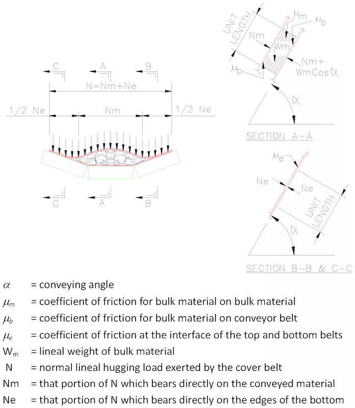
In its most rudimentary form the sandwich belt conveyor model was developed during the early 1950s. This allowed calculation of the required hugging pressure to develop the bulk material’s internal friction and preclude material slide-back. A modern, accurate version of the sandwich belt conveyor model is presented in Fig. 1. This model depicts accurately a de-rating of the material cross-section allowing an ample belt edge distance that can tolerate normal belt misalignment without material spillage. The calculations must thus recognize that only part of the hugging pressure is imparted onto the material with the remainder transferred belt edge to belt edge affecting a material seal. For mathematical development of the sandwich belt model, the reader is referred to Dos Santos and Frizzell [2].
The Loop Belt
The first lasting success and arguably the most important technological development in sandwich belt high angle conveying came in the early 1970s in the Loop Belt Elevator. The Loop belt, a continuous elevator of C-shaped profile, consists of an inner belt, which is supported on troughing idlers along a convex curve and an outer belt that imparts radial pressure, due to belt tension on the conveyed material onto the idler supported inner belt.
Interestingly the loop belt was first conceived as a high speed centrifugal belt, requiring neither inner belt nor sandwiching. Centrifugal acceleration of the material held it positively against a continuously curving outer belt until flung into free trajectory at the discharge. It was the practical consideration of an emergency stop under load that resulted in the design as we know it today.
Limited to approximately semi-circular conveying paths, the Loop Belt could not solve the problems of high volume conveying along a most direct path from loading point A to discharge point B. Nevertheless, this system gained great success in self unloading bulk carrying ships where the semicircular path is ideal. This system is the first to utilize all conventional conveyor componentry and smooth surfaced belts to achieve unlimited conveying rates of widely varying materials.
The Expanded Conveyor Technology
In 1979, a “High Angle Conveyor Study” was funded by the U. S. Department of the Interior, Bureau of Mines and executed by Dravo Corporation. The target applications in open pit mining, required high volume conveying rates of the coarsest materials along the most direct steeply inclined paths (along the pit wall. ) This precluded the C-Shaped Loop Belt profile but not the principles of operation. In depth research sought to unify the sandwich belt technology with the conventional conveyor technology, thus expanding the conventional conveyor technology and ensuring that none of the equipment is subject to adverse loading conditions beyond its intended use.
A study of all methods of steep angle conveying found the sandwich belt approach to be the most promising but also the least understood technologically. Basic research of sandwich belt conveyors began with the study “Cover Belts of the 1950s” and continued with study of all developments and variations through the 1960s and 70s. Like the 1958 Rasper review it was sought for characteristics and features that produced success in order to create a basis, complying to the findings, that would ensure success.
That rationalization is revealed in detail in the 1982 article “Evolution of Sandwich belt High Angle Conveyors” by Dos Santos and Frizzell [2]. The basis to ensure success is complete adherence to the rules of conventional conveyor technology while ensuring complete continuity of hugging on the material regardless of the conveying rate (from empty, through overload, with continuous and discontinuous material flow) and material size distribution. The former will ensure long life of the belting, components and the equipment while the latter ensures frictional development of the material within the sandwich and precludes any material slide-back.
Though the Loop Belt displayed the key characteristics, it failed to offer the desired profile and did not adhere to all design rules of conventional conveyors. Rather, it featured exceptions of convenience. The latter are to the detriment of the system.
“Evolution of Sandwich Belt High Angle Conveyors” has expanded the conventional conveyor technology into sandwich belt conveyors ensuring that such systems will have all of the operating and maintenance characteristics of conventional conveyors and will be as widely applicable. With emphasis on the technology rather than particular manifestation that writing [2] goes on to propose some five different sandwich belt conveying methods that when executed according to the guidelines established will result in success. Since the 1980s, there have been numerous successful commercial installations.
The Snake Sandwich Belt High Angle Conveyor
The DSI Snake Sandwich Belt High Angle Conveyor, evolved from the Snake Sandwich Conveyor, which was first introduced to the industry in 1982. The Snake system uses all (and only) conventional conveyor components and equipment and smooth surfaced belts (that are continuously cleaned by scraping. ) Hugging pressure on the conveyed material is imparted by a radial pressure which is induced by the inherent belt tension on an engineered curving profile. This is the most positive and gentle form of hugging pressure.
Possible Snake configurations are illustrated in Figs. 2 and 3. The most basic configurations are of simple C-shape and S-shape as shown in Fig. 2. Many such systems have been built and are in successful operation. Extended C and S-shaped profiles (Fig. 3) are facilitated by a multitude of profile curves with inflection zones between adjacent curves. Based on this writer’s experience, to meet the industry requirements, about half of the Snake units will be of simple profile as shown in Fig. 2.
The principles of sandwich belt high angle conveying are not new and reached technological maturity in the period 1979-1982. These principles have been demonstrated successfully in nearly 200 installations worldwide. Many of these installations, which are of Loop Belt systems, preceded 1979. Many more sandwich belt systems have been built for the low tonnage and duties of municipal waste and chemical sludge handling and other industries. Though these smaller systems are admirable, they are not suitable for the high volume requirements of open pit mining, transfer yard and dock and power plant applications.
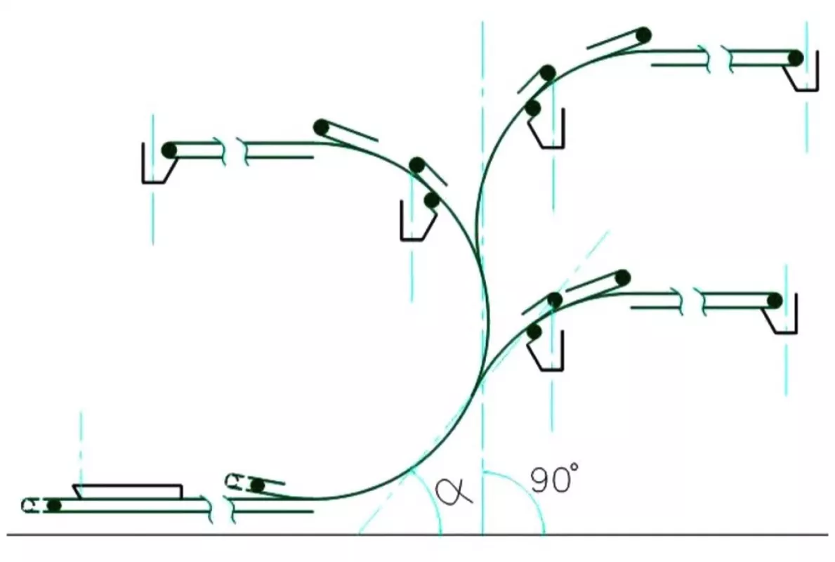
Fig. 2: Basic DSI Snake profiles.
|
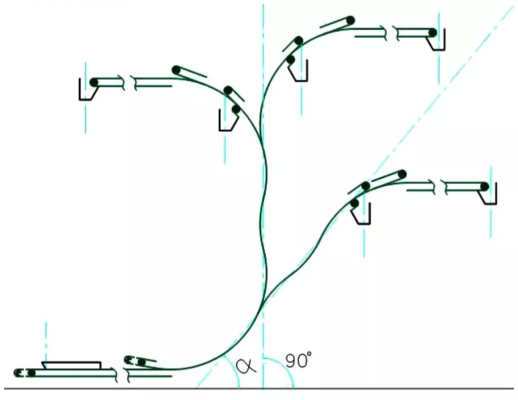
Fig. 3: Extended DSI Snake profiles.
|
Despite the numerous successes, sandwich belt conveyor systems have not been generally embraced as main stream conveyor technology rather these have been viewed as a specialized technology. The DSI Snake represents an expansion of the mainstream conventional conveyor technology, subject to all pre-established rules of good conveyor design. This will ensure long life of the equipment and belts, and low operating and maintenance costs. Applicability is as wide ranging as for conventional conveyors. Mainstreaming of the sandwich belt high angle conveyor technology is long overdue and this will come with wider and routine use.
The Cost/Value of High Angle Conveyors
The favorable economics of materials haulage by belt conveyors has long been acknowledged. The economics become even more favorable with increased volumetric rates and lifts. The superior reliability and availability of belt conveyors along with lower operating and maintenance costs are factors generally acknowledged. These favorable characteristics have also been demonstrated at numerous installations of sandwich belt high angle conveyors. Indeed, such systems, in compliance with the expanded conveyor technology, have equalled or outperformed the conventional conveyors at the same job site subject to the same or similar duty.
This article will not compare the economics of belt conveying against other haulage methods (such comparisons can be found in various references [3-7]). We will not compare the operational and maintenance characteristics and costs of conventional and sandwich belt conveyors. These are demonstrated to be equal in numerous applications. Instead, a comparison of the investment costs (engineering and supply) of four conveying paths to silos of various heights will be given.
The four conveying paths, shown in Fig. 4 are by a conventional conveyor and three variations of the Snake sandwich belt conveyors as follows:
- Conventional conveyor at 15° slope.
- Snake at 45° slope.
- Snake at 60° slope.
- Snake at 90° vertical.
The silo heights vary from 17.8 to 73 meters with the system lifts being an additional 3 meters. Besides total investment costs we will look at cost breakdown. Such breakdowns reveal economic sensitivity and imply operating and maintenance characteristics. Some important non-cost factors will also be analyzed.
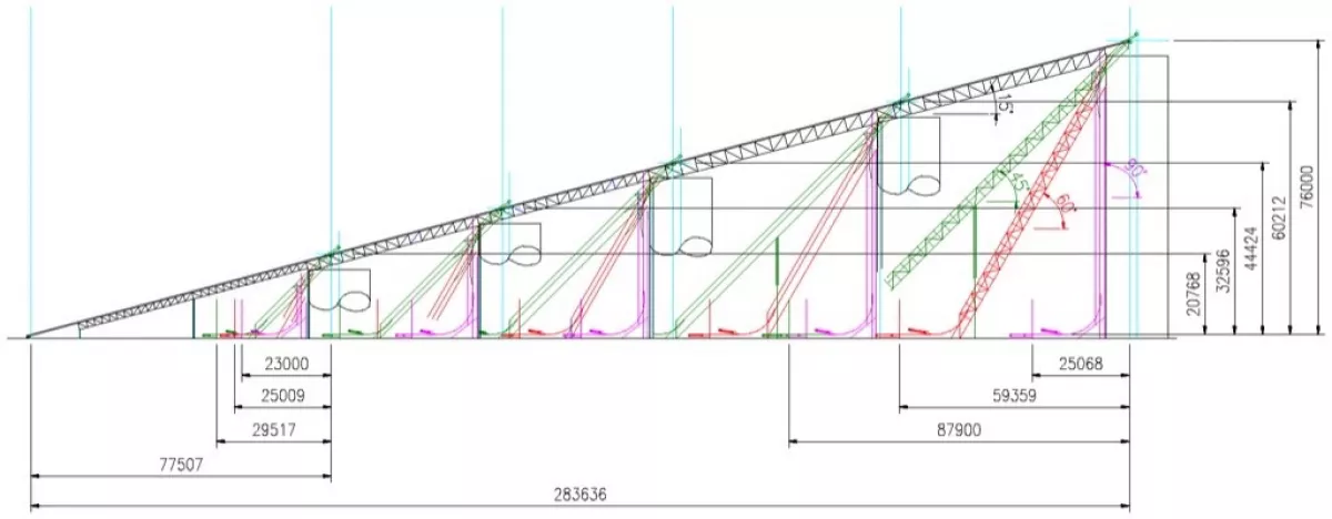
Fig. 4 shows the configurations of the conventional and high angle conveyor elevating options to silos of increasing height. Overall dimensions at the illustrate the significant differences in the foot print required for the alternate profiles. Table 1 summarizes the technical basis for the design and estimating of the various elevating options.
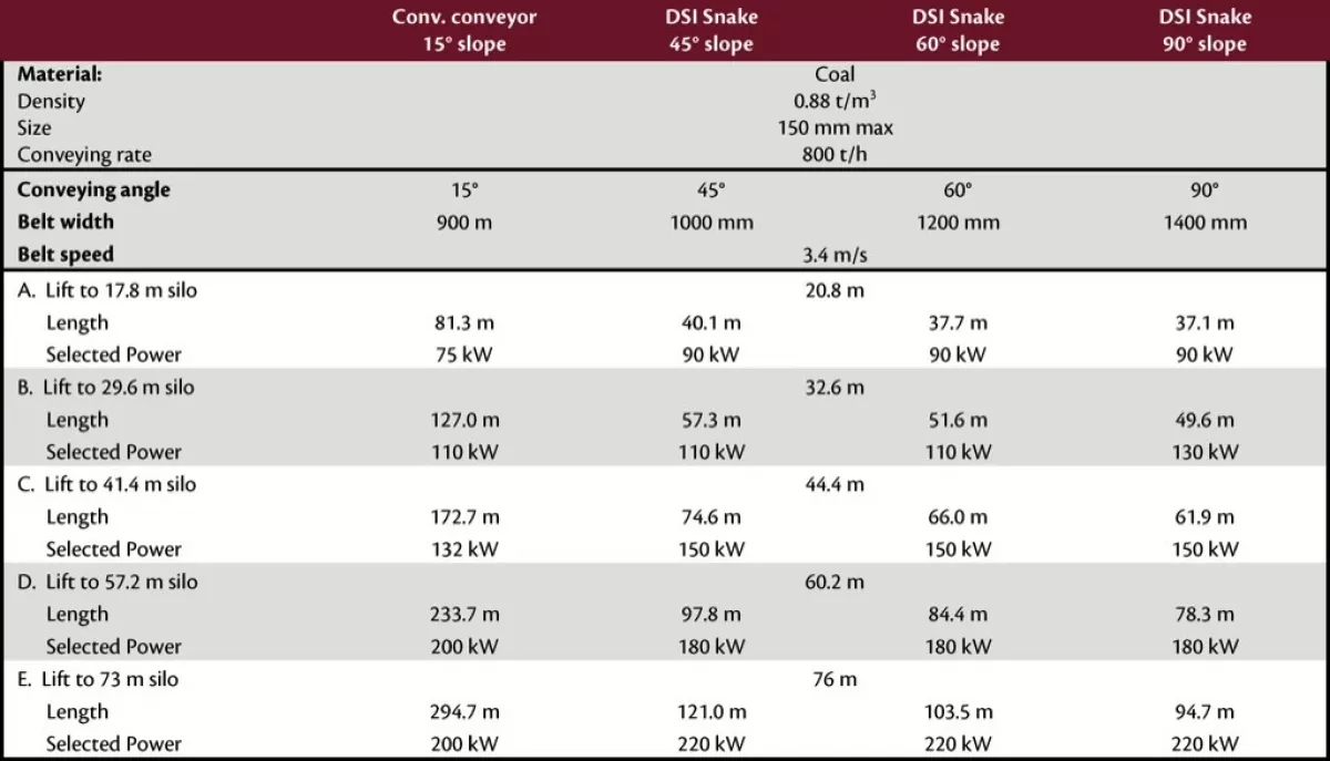
Belt Widths
It is important to note that increasing belt width is required with increasing angle. Compared to the conventional troughed belt conveyor a sandwich belt high angle conveyor carries a lesser material cross-section for a given belt width, having a larger material-free edge distance and ample margin against overload. Furthermore, the material cross section at a sandwich conveyor is de-rated with increasing high angle. Accordingly, the vertical sandwich belt conveyor requires the widest belts (1400 millimeters), components and structure for the same coal throughput rate and belt speed. The cost consequence is seen at the conveyor equipment and components summary. On the other hand, it does result in heavier, possibly more durable equipment.
Drive Power
The drive power chosen differs from the calculated required as we selected the next commonly available motor size and drive components. This is further aggravated by our choosing equal drive units at the top and bottom belts of the DSI Snakes. The results in investment costs appear as less than smooth curves (see Fig. 5) at the conveyor equipment and components summary.
Conveying Angle and Safety against Material Slide-back
Safety against material slide-back is a very important factor in any materials elevating system. Such a consideration might lead the conservative to erroneously choose the conventional conveyor as the safe solution. In fact, there are many documented cases of conventional slope conveyors at inclines of 15, 16 and 17 degrees that experience frequent material slide-back, especially when excessive moisture or frost are involved. This writer knows of no material slide-back at any of the more than 100 sandwich belt conveyor designed in compliance with the “expanded conveyor technology.” The safety factor against slide-back is well known at a sandwich belt conveyor system because it is chosen when choosing the induced hugging pressure. Indeed such a selection does not exist for conventional slope conveyors and an equivalent safety factor against material slide-back would limit conventional conveying angles to less than 12 degrees even with coal and crushed rock.
As a consequence of experiencing material slide-back with 16 and 17 degree conveyors, a study at a major coal company objectively determined and resolved that their conventional conveyor slopes should never exceed 12 degrees. Their next elevating conveyor project was designed and built in compliance with new criteria. The cost impact on this project was so high as to immediately cause reconsideration of the conservative criteria. It was then resolved that their conventional conveyor slopes should never exceed 14 degrees. Such cost driven compromises are unnecessary with the sandwich belt conveyors that are pursuant to the described development.
Structural Optimization
For the sake of a fair comparison it was important to structurally optimize the alternate elevating systems, especially the conventional 15 degree slope conveyor. It is well known that structural bents and towers become very massive and expensive with height. In order to minimize the mass and cost of structural steel, we must increase the structural spans with height so that we can minimize the number of very high and massive bents. In this case we have chosen truss spans, beginning from grade, of 30.5, 45.7 and 61 meters for the first, second and third pairs of trusses. Having established approximate structural optimization for the conventional 15° conveyor, we have chosen silo wall locations at the bents.
Basis for and Presentation of Costs and Pricing
A fair costing comparison must be in compliance with a single and uniform design and pricing philosophy. Every buyer and every seller knows that the same inquiry and specification will result in, at times, widely varying price offers by various manufacturers. Even the same manufacturer’s offer will vary depending on the competitive situation and his desire for the work (i. e. having a high or low current work load. ) Though our estimates here are in compliance with the uniform design and pricing philosophy of Dos Santos International, we present all pricing of comparison in the form of an index. Any reader can then normalize this cost comparison according to their own buying and/or selling experiences and policies.
Cost Comparison
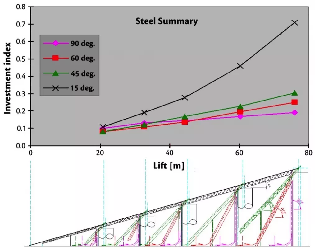
Fig. 5 graphs the investment cost (engineering and supply) for the four elevating systems as a function of increasing silo height. This does not include civil, foundations or installation. It is not surprising that the conventional 15 degree slope conveyor proves least costly when elevating to the lowest silo of 17.8 meters height. However, the cost of the conventional conveyor system increases exponentially with height. Beyond approx. 33 meters of lift it becomes the most expensive solution. At 76 meters of lift its cost exceeds the sandwich belt solutions by a range of 60 to 88 percent.
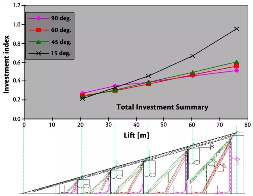
On the other hand the variation in investment cost for the sandwich belt solutions is approximately linear with silo height and quite modest with regard to each other. At the lowest silo height, a sandwich belt system of 45 degree slope has a 0.23 investment index compared to 0.24 (4 percent higher) for a 60 degree slope and 0.27 (17 percent higher) for the vertical unit. At the highest silo, the vertical sandwich belt system has the lowest investment index at 0.51 compared to 0.56 (10 percent higher) for the 60 degree slope and 0.60 (18 percent higher) for the 45 degree slope.
Figs. 6 and 7 show the relative make-up of the investment costs. Fig. 6 graphs the investment in conveyor equipment and components. This includes belting, idlers, pulleys, drives, switches etc. It can be seen that the investments increase linearly with height.
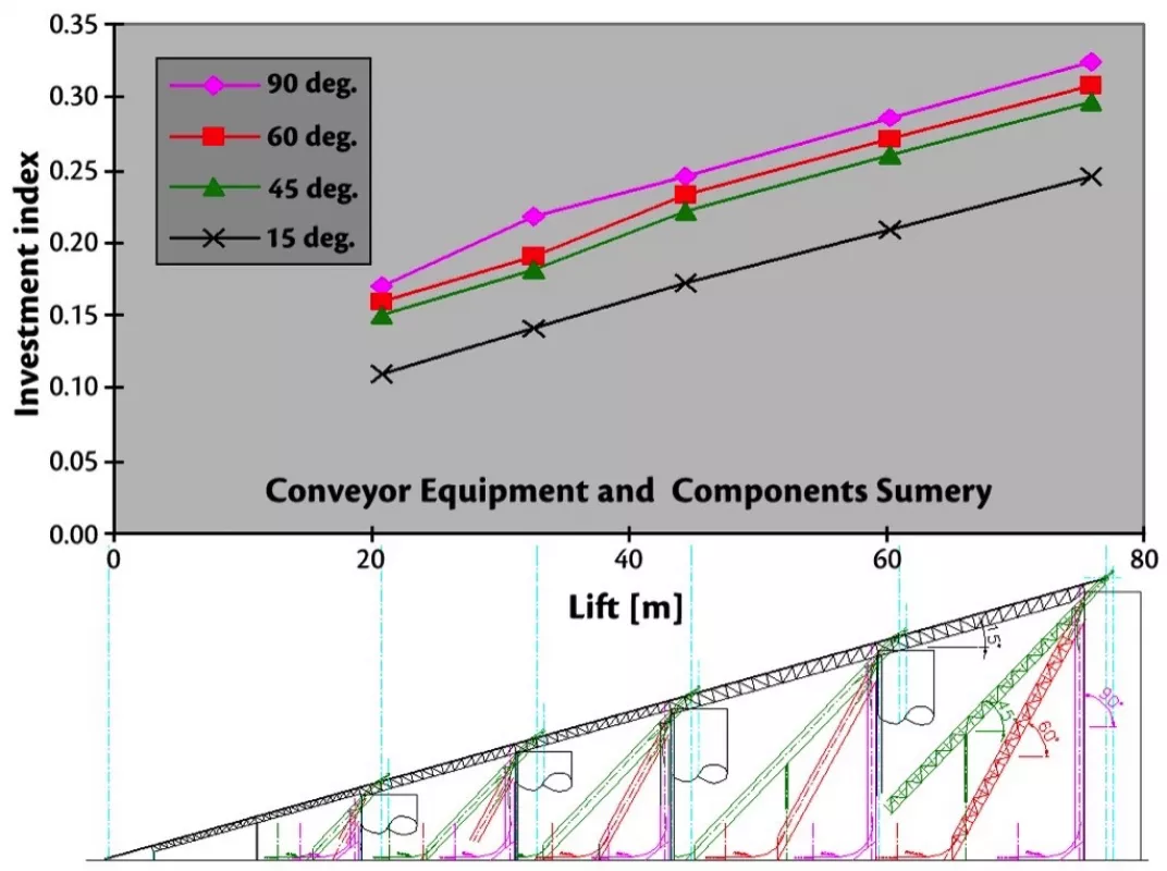
Furthermore, the conventional 15° conveyor has always the lowest investment in conveyor equipment and components while the vertical sandwich belt conveyor is always the highest. This is due to the required wider belts and corresponding equipment. The great cost differentials between the conventional 15? slope conveyor and the sandwich belt conveyors are owing to the great difference in structural steel requirements, as illustrated in Fig. 7. The steel in this case includes all truss spans, bents, terminal framing, covers, access walkways and stairways, chutes, skirts etc.
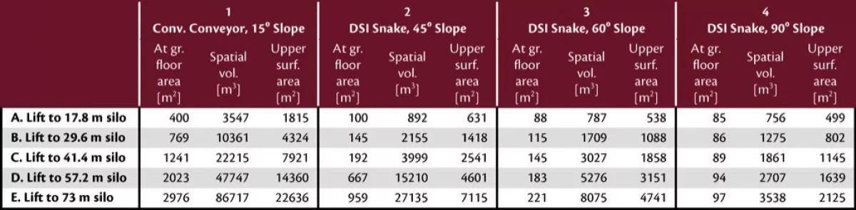
Some Important Indirect Cost Factors
It is worth noting some important indirect cost factors for comparison. Table 2 shows a comparison of displaced projected (ground) areas, spatial volumes and perimeter area, above grade, for the different elevating systems. Significant indirect costs can be associated with each of these quantities. For the displaced ground area there is a real estate cost. For the spatial volume and perimeter area above grade there is a very real cost when the conveying system is part of a housed or covered facility. The cost of the building or covering is directly related to the displaced spatial volume and exposed surface area. In the case of heated facilities, required in frigid climates, heat is lost through the exposed surface area in direct proportion to that area. Also important is the minimal environmental footprint of the high angle conveyor solutions.
Latest Sandwich Belt High Angle Conveyors, Examples of Indirect Cost
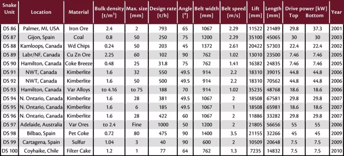
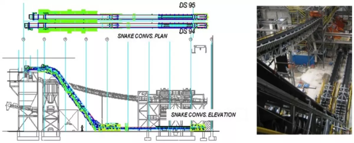
Table 3 summarizes some of the latest sandwich belt high-angle conveyor systems. Each has its unique project account and reason why it was the best solution. We will high light three projects which are examples of the significant indirect costs.
Snap Lake and Victor Project
The indirect costs are real and significant. Such costs motivated DeBeers Canada, more than twenty years ago, to incorporate sandwich belt high angle conveyors into the planning of the recovery facilities of their two premier diamond mines, at Snap Lake, Northwest Territories, and at Victor Project, Northern Ontario, Canada.
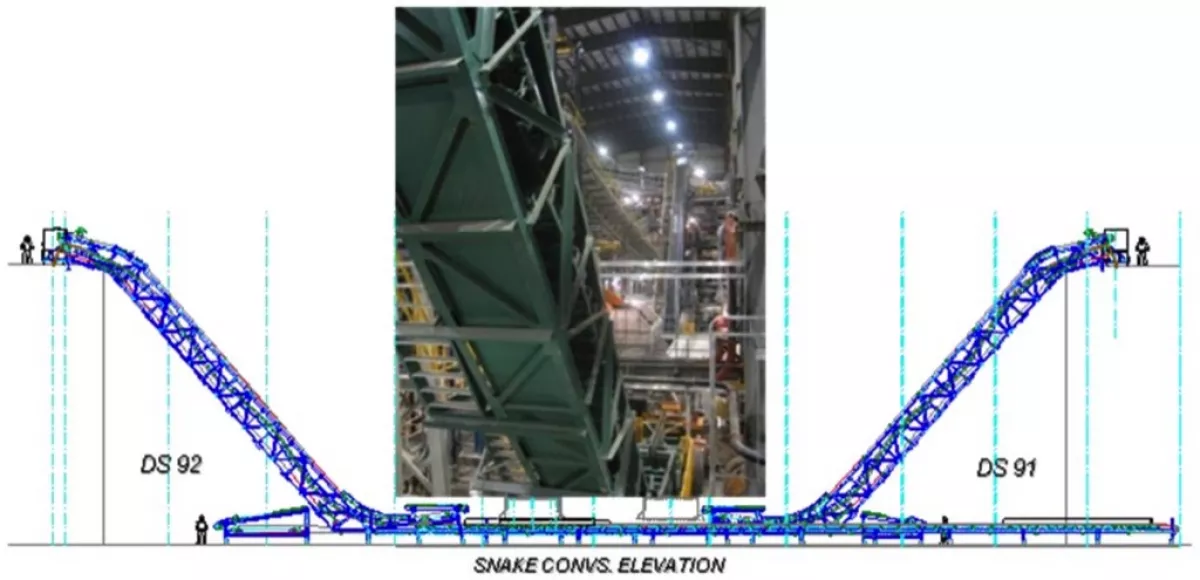
Fig. 8 illustrates how the two Snake conveyors define the size of the recovery facilities, each conveying to the opposite side of the building. Conversely one can extrapolate how much larger the building would be if conventional conveying angles were use to achieve the required material lifts to the various crushing and screening stages of the recovery functions. Located in Canada’s Northwest Territories, near Yellow knife the facilities are routinely subjected, in winter, to frigid temperatures below minus 40 °C. This requires heating the large facilities throughout the winter at a great expense in natural gas. That expense is minimized as is the environmental footprint because of the shorter elevating distances possible with high angle conveyors that are suitable for the handling requirements.
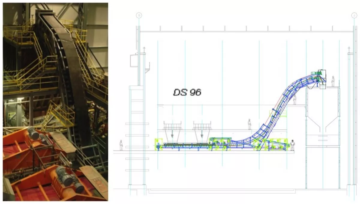
The story at the DeBeers Victor Project is similar and represents a continuation of confidence in the sandwich belt high angle conveying systems. The Victor project is located in Northern Ontario, west of James Bay in the region of Attawapiskat. Like Snap Lake the climate is frigid in the winter and the facilities must be continuously heated. The arrangement at Victor is somewhat different than Snap Lake with twin Snake Conveyors (one for coarse pebble ore and the other for granular ore) traveling in the same direction from the secondary screen, at one end of the building, to the next screening and crushing stages at the other end (Fig. 9). A third Snake unit (Fig. 10), running in the perpendicular direction, transfers coarse pebble ore back to a crusher feeding conveyor. This unit in affect defines the width of the building.
The building is shorter and narrower because of the high angle conveyors, minimizing the environmental foot print, the building costs and the fuel costs to heat the facilities in winter.
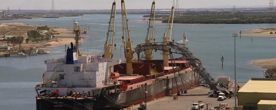
Snake Ship Loader at the Port of Adelaide, Australia
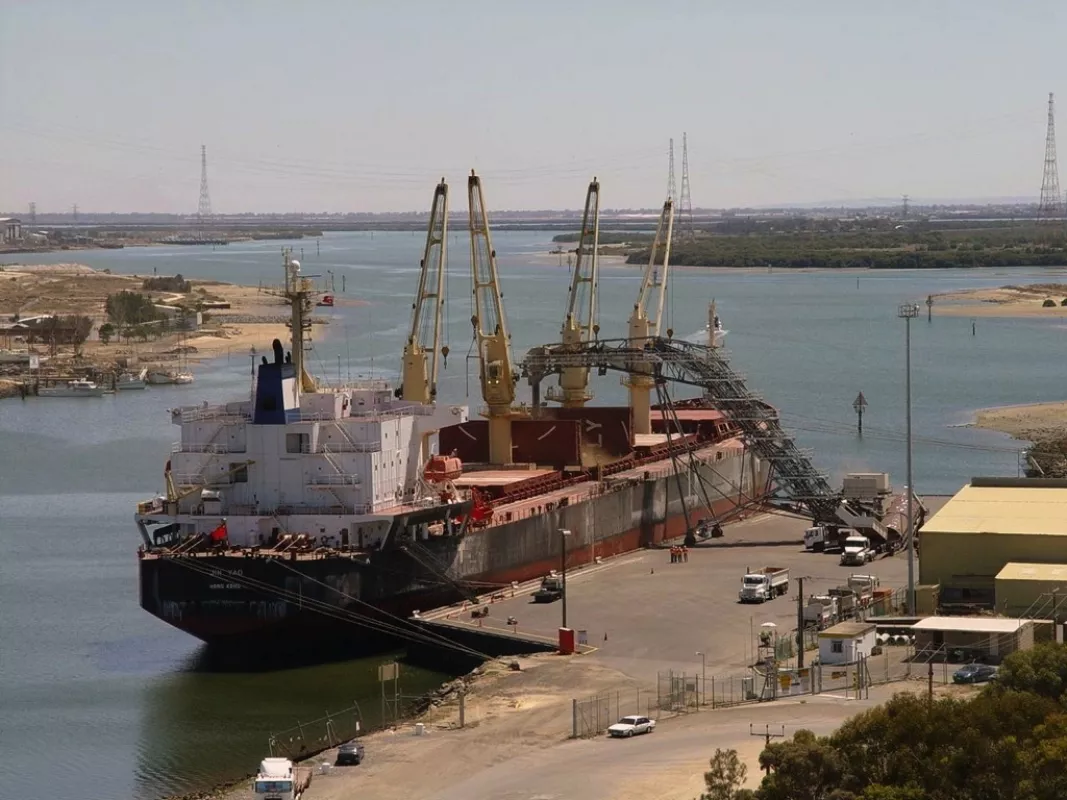
The indirect costs are also real and significant at the Port of Adelaide, NSW, Australia. There the savings are in dock costs. Fig. 11 shows the Snake Ship Loader maneuvering easily within a narrow dock space. The height required to load the Panamax class ships could not be accomplished with the low angle of the conventional ship loaders. Extensive additional dock construction would be required with the conventional systems.
What is the Best Angle?
The best elevating profile depends largely on site and functional requirements. In general, the best solution is the most direct path from loading point A to discharge point B. The present study however reveals economic comparisons that would prompt a combination conventional conveyor along the ground to an elevating sandwich belt conveyor, even when ample space exists for a conventional conveyor solution. This can be a sandwich belt conveyor with a long approaching bottom belt. In general, loading point A and discharge point B will be located for the best use of space. The total investment comparison reveals large differences, at the very high lifts, between the conventional and the sandwich belt conveyors but not among the sandwich belt systems. At the highest lift, a 60 degree DSI Snake profile has approximately 10 percent higher investment than the 90 degree (vertical) DSI Snake. A 45 degree profile has approximately 18 percent higher investment.
Operational considerations might warrant the higher investment in a 60 degree system, or even a 45 degree system. Such considerations are (1) System clean-up and (2) System access.
Sandwich belt systems at any angle can be designed spillage free. Minor material carry back can occur due to none perfect belt scraping and even the occasional leakage, due to poor belt alignment and other aggravations. The magnitude of the accumulation is far less important than its nature and consequence. At a vertical system such carry back does not have a clear path away from the equipment and tends to accumulate progressively on the rolling equipment. Periodic cleanup is required, typically by high pressure wash-down. Wash-down water at the outer parts of the wing rolls has contaminated the bearings and caused frequent premature bearing failures requiring high rates of roll replacement. No such phenomenon has occurred at sandwich belt conveyors of any incline less than vertical. Any carry back tends to fall away clear of the rolling equipment and build up is not progressive towards the bottom.
Access to the equipment is important in any case. Many specifications require access by stairway (vertical ladders are not allowed). The maximum stairway slope, according to architectural standards, is 50 degrees. At higher angles step ladders (51 to 70 degrees) or ladders (71 to 90 degrees) must be used, with safety lines or safety cages and landings. The cost of stair towers can sometimes approach the cost of the sandwich conveyor systems.
In view of the modest premium shown in Fig. 5 and consideration 1 (material carry back), it is this writer’s opinion that the 60 degree DSI Snake solution with access by ladders and landings will prove very economical and most reliable. Furthermore, if a stairway is required then the additional premium show in Fig. 5 may be warranted making the preferred conveying angle less than 50 degrees.
Many cases of limited space will warrant vertical systems. It is not our intent to discourage these as the cited problems can be resolved by conscientious design and clean-up procedure.
Concluding Remarks
Complete rationalization of the sandwich belt conveyor technology in the conventional conveyor technology was achieved in the period 1979 to 1982. Many successful sandwich belt steep and vertical conveyors have been built in compliance with that rationalization and have demonstrated the performance characteristics of conventional conveyors. The DSI Snake is the only high volume sandwich belt system to utilize all and only conventional conveyor equipment and componentry. Material hugging pressure is induced by exploiting the inherent belt tensions on an engineered alternately curving (snaking) profile. An investment comparison shows great savings when conveying to high silos with DSI Snake sandwich belt conveyors at various angles from 45° to 90° (vertical). To date, sandwich belt conveyors have not been widely recognized as mainstream technology despite the many successful systems and the demonstrated economies. There is no basis for reluctance in the wide use of sandwich belt conveyor systems. Such systems should be embraced as mainstream technology and exploited to lower the costs of silo loading and other applications.
This article has focused on the cost of elevating materials to silos. High angle conveying is equally advantageous in elevating to other covered storage systems such as storage barns and domes. Dome type structures for covered storage have gained prominence and use. The DSI Snake profile is ideal for continuously elevating materials to the top of such domes sharing a compatible curving geometry. Enroute to discharge, at the top of the Dome, a DSI Snake system will impart a gentle distribution of structural loads onto the Dome structure. The combination will be an aesthetically pleasing, uncluttered system.
■

