
The construction and the characteristics of the belt substantially influence the quantity of the indentation rolling resistance. Thus, the thickness of the bottom cover as well as the used cover plate material affects the running resistance. A reduction of the indentation rolling resistance leads to significantly lower power requirements without any changed boundary conditions and helps to improve the particular efficiency of belt conveyors further on.
Due to the specific stresses, the material properties determined in laboratory scale test procedures have a limited validity about the suitability of various rubber materials for bottom cover plates. At the Institute of Transport and Automation Technology (ITA), the indentation rolling resistance can be measured on a two drum revolution test rig. Corresponding to realistic conditions, the test parameters load, diameter of the idler, belt speed and ambient temperature can be adjusted. Hence, the test rig allows a comparison of different conveyor belts under realistic conditions.
To verify the transferability of the test results to the practice, the running resistance of a conveyor belt was determined in field measurements on a running system, using measuring idler garlands. Subsequently, the indentation rolling resistance related to belt width was determined for the same belts at ITA and calculated from these results for the array of the measuring idler garland. A very good correlation was proven between the results from the test rig and the results from the field measurements.
The experience and knowledge from the studies on the belt width related indentation rolling resistance of conveyor belts is currently subject of the creation of various DIN standards. These standards will include the test methods and the use of test results for the calculation of the belt width related indentation rolling resistance of belt conveyors.
1. Introduction
Belt conveyors are the adequate solution for the transport of large mass flows from a technological, an economical and an environmental point of view. From the industry, longer conveying distances and a higher mass flow are demanded. Consequently, a higher power requirement for operating such conveying systems is needed.
The most significant savings potential on the running resistance of a conveying system is mainly given by the indentation rolling resistance of the belt. This results from a lossy deformation of the belt during the movement over the idlers. For long distance conveying systems, these losses can be up to 60% of the total energy [1,2]. For this reason, at the Institute of Transport and Automation Technology many studies on the indentation rolling resistance and its influence parameters were performed on different two drum test rigs. It could be shown that the quantity of the indentation rolling resistance is largely determined by the construction and thereby the properties of the conveyor belt. A reduced thickness of the bottom cover plate influences this running resistance as positive as the use of a suitable cover plate material [1]. Investigations showed a lower energy consumption due to a lower amount of carbon black in the elastomer. Even the basis elastomer has a significant influence as natural rubber has up to 30% better energetic properties than synthetic rubber. Furthermore, the insertion of a polyamide transverse reinforcement also favourably effects the indentation rolling resistance.
Plant specific parameters can have a significant influence on the indentation rolling resistance as well. It increases progressively with increasing loads and minimally with increasing belt speed [3]. The measurements undertaken by Schwarz showed more dependencies concerning the behaviour between the belt and the idlers and the related energy loss. By an enlarged idler diameter the indentation rolling resistance can be reduced hyperbolically, whereas rubberised idlers led to an increase of this running resistance [4].
As a result of further investigations it was demonstrated that the indentation rolling resistance additionally increases due to applied unequally distributed loads. Also the belt tension has been subject of various experiments. Different measurements showed that an increasing belt tension leads to a weakly decreasing indentation rolling resistance. With a strong temperature dependence, another impact factor was demonstrated by an air conditioned enclosure of the constantly optimised test rig. At very low ambient temperatures, the indentation rolling resistance is up to 50% bigger than at temperatures of 20°C [1].
To verify of the applicability to the large-scale practice, Geesmann and Wennekamp undertook field measurements on large-scale belt conveyors [5,6]. Within these measurements and the usage of different measuring garlands, Geesmann found that for similar bottom side cover plates the indentation rolling resistance of new conveyor belts is much bigger compared to the indentation rolling resistance of conveyor belts after several years of storage or in appropriate use [5].
Wennekamp proved a good and reliable correlation between the results of measurements on the test rig for the determination of the indentation rolling resistance and the results of measuring garlands used at belt conveyors for field measurements [6]. For this reason, the measurement results of the test rig were converted due to the conventional troughed belt geometry and the related normal force distribution on the idlers and afterwards compared to each other.
Based on the reliable strong correlation to realistic large-scale conditions, the test procedure and conversion process developed at the Institute of Transport and Automation Technology has been published in the new version of DIN22101:2011 and the new DIN22123:2012 “Conveyor belts – Indentation rolling resistances of conveyor belts related to belt width – Requirements, testing” [7,8].
2. Indentation Rolling Resistance Test Rig
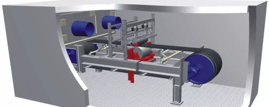
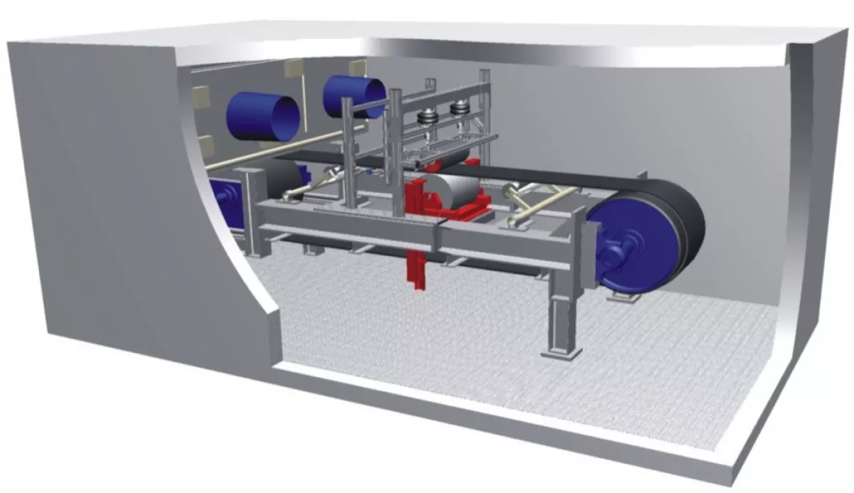
The measurement of the indentation rolling resistance at the ITA was carried out according to the established test method developed by ITA where the conveyor belt is applied to the test rig with the cover to be tested turned upside down according to Fig. 2.
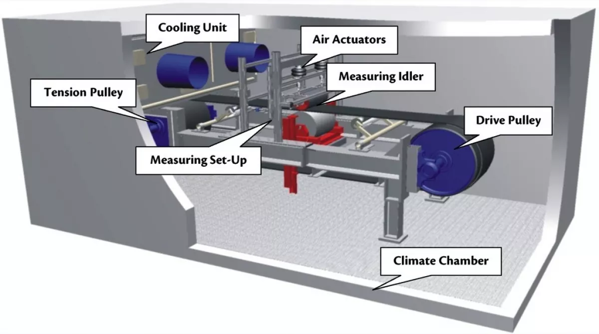
The shown test rig consists of a drive pulley and a tensioning pulley, both with a diameter of 800 mm. The distance between the two axes is approximately 4000 mm. The test rig is driven by a direct current motor with 36 kW power and the variable belt speed can be chosen up to a maximum of 8 m/s. In the middle of the test rig a special measuring device is installed which measures on the top-run of the belt.
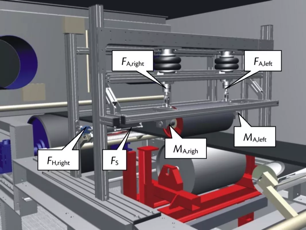
For the measurement a centrically positioned idler is installed in an adjustable frame. The idler is pressed by two pneumatic cylinders onto the belt with a defined force which is measured by two force transducers (FA, right; FA, left). The diameter and the length of the idler can be varied in a given range. For an opposing support a finely finished idler with a diameter of 400 mm is installed.
For determination of the indentation rolling resistance, the force acting in horizontal direction on the idler and therefore on the frame of the test rig is measured by means of three force transducers (FH, right; FH, left; FH, middle). To separate the actual indentation rolling resistance from the horizontal force measured, the part of the horizontal force caused by the idler running in a horizontal direction must be subtracted. For this reason, the idler is supported on both sides by torsion transducers that measures the idler running resistance (MT, right; MT, left). Another force transducer (FS) measures the force lateral to the running direction to avoid a possible tilting between the idler and the belt. The described measuring device is shown in the following Fig. 3.
The test rig is set up in a thermally insulated housing to enable adjustment of the ambient temperature in the range from -50°C to +60°C by means of a refrigerating set or heaters. Besides the measuring of the ambient temperature a second heat detector is installed. This detector is within a belt sample and detects the live time belt temperature. The belt temperature changes slower than the ambient temperature, due to the thermal characteristics of the elastomer of the belt. Therefore the measuring temperature is defined by the belt temperature to ensure that the test belt has a homogeneous temperature.
Beside the tested belt specimen, the adjustable basic parameters are the width related load, the temperature, the belt speed and the idler diameter as well as the idler length. For the indentation rolling resistance the influence of the load and the temperature are clearly larger than the influence of the belt speed or the geometry of the idler [3-5,9]. But for a practical study of certain conveyor systems these parameters with lower influence can be examined too.
Recent measurements at ITA show that the indentation rolling resistance can be reduced over 50 % by using different fillers for the elastomer of the belt. The following Fig. 4 shows the highest and lowest measured values for the indentation rolling resistance (IRR) for all analysed belts of the type ST 4500 16:8 at the ITA with a belt temperature of 20°C.
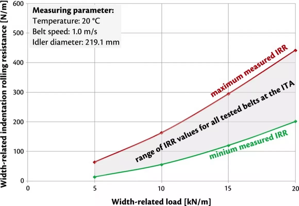
Fig. 4: Width related indentation rolling resistance at 20°C belt temperature over the width related load for belt type ST 4500 16:8.
|
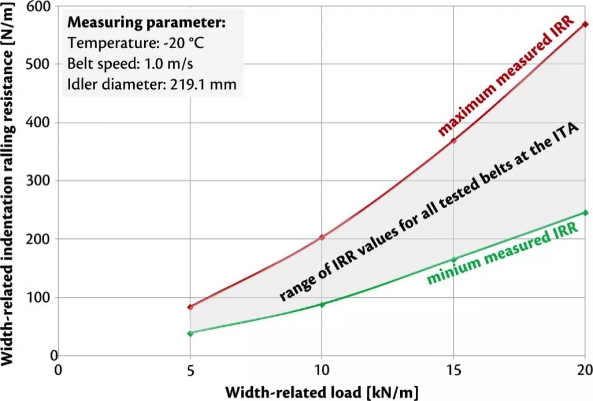
Fig. 5: Width related indentation rolling resistance at -20°C belt temperature over the width related load for belt type ST 4500 16:8.
|
These two figures show that the indentation rolling resistance due to targeted modification of the fillers of the elastomer can be reduced over 50% within the examined parameter range. Additionally the figures show that the indentation rolling resistance increases with decreasing temperature.
The comparison of the results from the test rig to the field measurements on a real conveyor system are possible due to the variation of the belt speed and the geometry of the measuring idler.
3. From Test Measurements to Practice
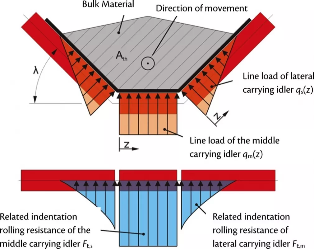
For the transmission of the measured values for the indentation rolling resistance under laboratory conditions into the practice for a conventionally troughed, horizontal and linear conveyor system, the following model by Grabner is used and shown in Fig. 6 [10,11]. The calculation considers an idealised normal force distribution. That means a constant force distribution for the middle carrying idler and a linear rising distribution for the lateral carrying idlers.
The following equation for the axial contact line length bR between idler and conveyor belt generally applies for the normal force FN which acts on each idler.
| (1) |
For a constant acting line load on the middle carrying idler in direction of the normal force the result of the integral is the next equation.
| (2) |
For rising respectively falling line loads acting on the lateral carrying idlers, the following relationship applies.
| (3) |
The relationship between the width related load and the width related indentation rolling resistance for the investigated conveyor belts can be described by the following approximate function.
| (4) |
The variables a and b are dependent on the measured profile of the width related indentation rolling resistance. The indentation rolling resistance along the idlers FE’’ results from the integration of the course on the particular axial contact line length bR.
| (5) |
The sum of the indentation rolling resistances acting on the lateral and middle carrying idlers is the result for the indentation rolling resistance for one garland of the conveyor system.
| (6) |
The total indentation rolling resistance acting on the garland of a conveyor system is calculated to Eq. (6) by solving and using of Eqs. (2) and (3) for Eq. (5).
| (7) |
The indentation rolling resistance of an idler garland of a conveyor belt system can be calculated by Eq. (7) according to Wennekamp [6]. By given knowledge of the details about the geometrical parameters, the acting forces and the distribution of the forces as well as the width related indentation rolling resistance from results of the test rig at the ITA, it is possible to calculate the indentation rolling resistance for an idler garland of a conveyor system.
4. Field Measurements
For the verification of the results determined on the indentation rolling resistance test rig of the Institute of Transport and Automation Technology, these results were compared to results from field measurements at RWE Power AG. These field measurements were taken at the belt conveyor F26 in the open pit mine Hambach with an axis-to-axis distance of 1140 m. For measuring the running resistance of the belt, a simplified version of the measuring system of Geesmann was used [4]. On an expanded frame, the attachment points of an idler garland were fixed to load cells in all spatial directions. The measuring array can be seen in Fig. 7.
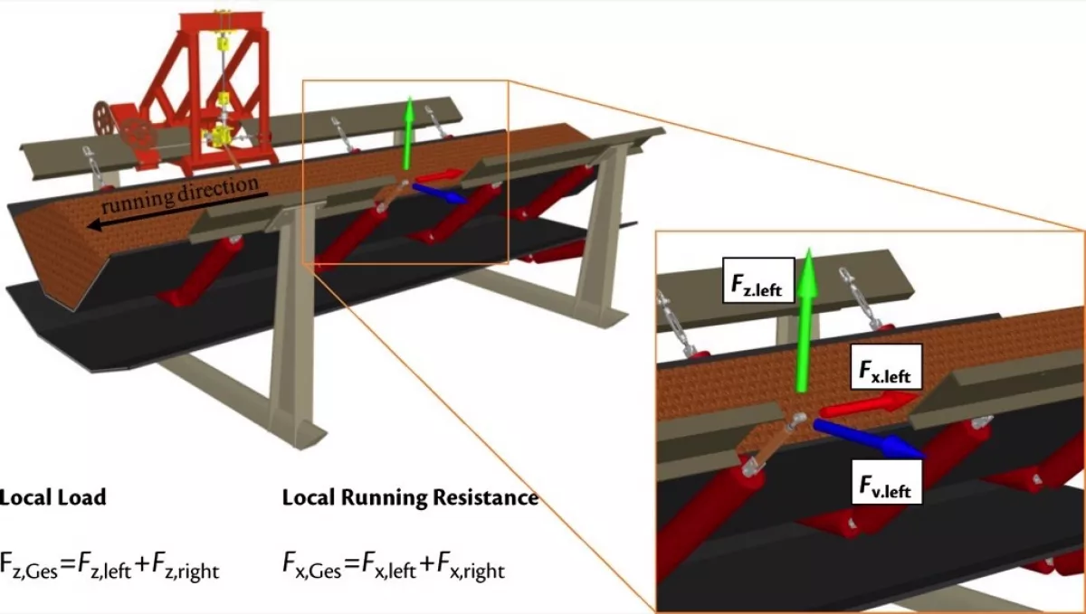
The sum of the measured forces Fx, Ges counteracts the running direction of the belt and equals the corresponding local running resistance of the belt. The local load due to the gravitational forces acting on an idler garland consisting of belt and conveyed weight is summarised in the force Fz, Ges. The forces in the lateral direction are recorded for monitoring purposes and are not taken into consideration during this evaluation.
The ST4500 16:8 conveyor belt consisted of 15 various belt sections, supplied by various manufacturers and primarily differs regarding the bottom side cover plate compounds. To assign the measurement data from the measuring idler garland to the respective belt sections, the belt segments were equipped with transponders. In order to determine the correlation between the results of the field measurements and the results from the test rig, specimens of the belt in the conveyor F26 were cut out and tested in the test rig of the ITA.
In order to verify the correlation between the field measurements and the measured indentation rolling resistance on the test rig, the force acting upon the idler garland in running direction of the belt in dependence of the vertical load respectively the mass flow was evaluated. To separate the indentation rolling resistance from these results, further components of the running resistance have to be considered. The flexure resistances of the bulk material and the belt were calculated using the approach of Limberg. The frictional resistance from idler self alignment was calculated using the approach of Grimmer. The idler running resistance of the idlers used in the garland was determined in the idler test rig of the ITA.
With the explained calculation method for the determination of the acting indentation rolling resistance on a troughed belt and the calculation of the other components of the running resistance, the calculated running resistance can be compared to the measured running resistance of the belt conveyor, see Fig. 8.
![Fig. 8: Calculated and measured values and amounts of the running resistance on an idler garland of the examined conveyor belt 5 at a mass flow of 30,000 t/h and a temperature of 20°C [5].](https://www.bulk-online.com/sites/default/files/public/styles/basic_max/public/2023-01/HoetteS_Hannover_ab08_img.jpg.webp)
At a mass flow of 30,000 t/h and an ambient temperature of 20°C, the indentation rolling resistance has a share of 62%, the largest amount of the running resistance of the described belt conveyor. The sum of the flexure resistances of bulk material and the belt is much lower at 19%. The frictional resistance caused by the idler self alignment has an amount of 15%, with 4% the idler running resistance has the lowest share of the running resistance. In total, this results in a running resistance of 392 N per idler garland for the tested belt. The measured and calculated value of the running resistance of the belt conveyor F26 at a mass flow of 30,000 t/h with the same belt corresponds to 390 N per garland [5].
The comparison between the measured running resistance of the belt conveyor F26 and the running resistance determined and calculated in test rig experiments shows a good and reliable correlation.
5. Summary and Conclusions
Within the research project undertaken by RWE Power AG, PHOENIX CBS GmbH and the Institute of Transport and Automation Technology (ITA) of the Leibniz Universität Hannover, a good and reliable correlation was confirmed between the quantity of the width related indentation rolling resistance measured on the test rig of the ITA and field measurements for the determination of the running resistance in dependence of the mass flow. During several years, the test rig for the determination of the width related indentation rolling resistance of the ITA has been constantly improved. Corresponding to realistic conditions, the test parameters load, diameter of the idler, belt speed and ambient temperature can be adjusted.
The test results are measured on a flat belt specimen, hence the indentation rolling resistance of conventionally troughed conveyor belts has to be calculated due to their specific stress distribution. The calculation basis evaluated within the research project led to the new DIN22123:2012 “Conveyor belts – Indentation rolling resistances of conveyor belts related to belt width – Requirements, testing”. Even in the new version of DIN22101:2011 “Continuous conveyors – Belt conveyors for loose bulk materials – Basis for calculation and dimensioning” the described calculation of the indentation rolling resistance is an important part in the dimensioning process of belt conveyors.
Taking these calculations into consideration, quantitative and system-specific statements about the local indentation rolling resistance and moreover the running resistance of the entire belt conveyor and its power consumption are possible.
■
