
2.3 Design Considerations
Based on the above equations, several observations can be made in relation to reducing rotating resistance. Figs. 5 and 6 summarise the relationship between idler roller rotating resistance and temperature, demonstrating the contribution from each component in Fig. 5 and, by way of example, measured data for different manufacturers in Fig. 6.
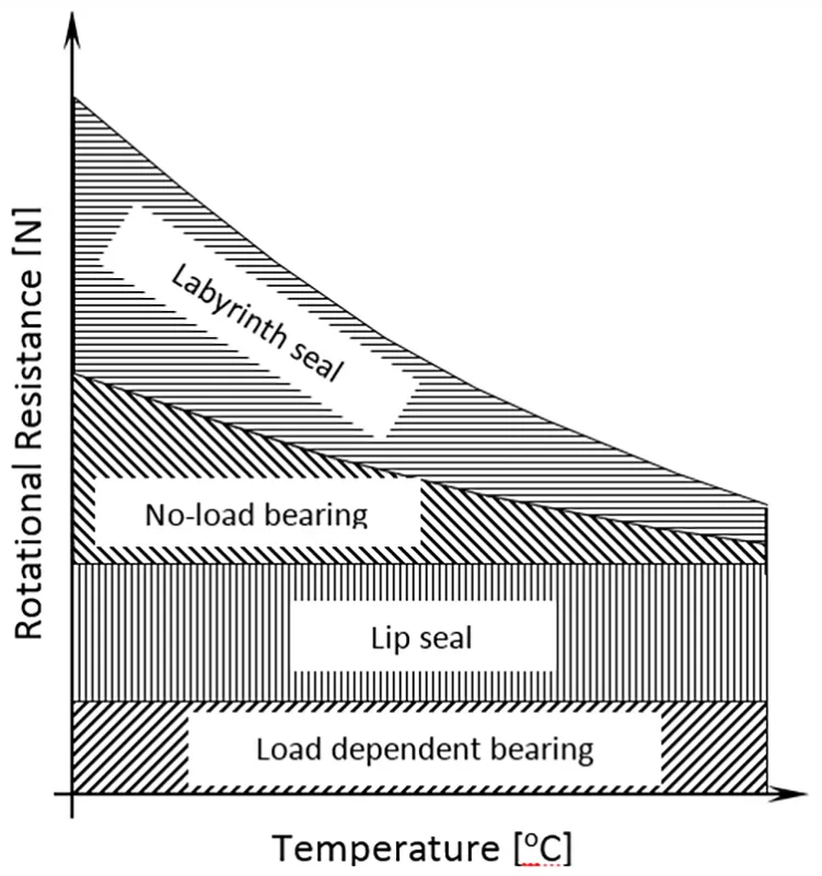
Fig. 5: Idler roller rotating resistance versus temperature
|
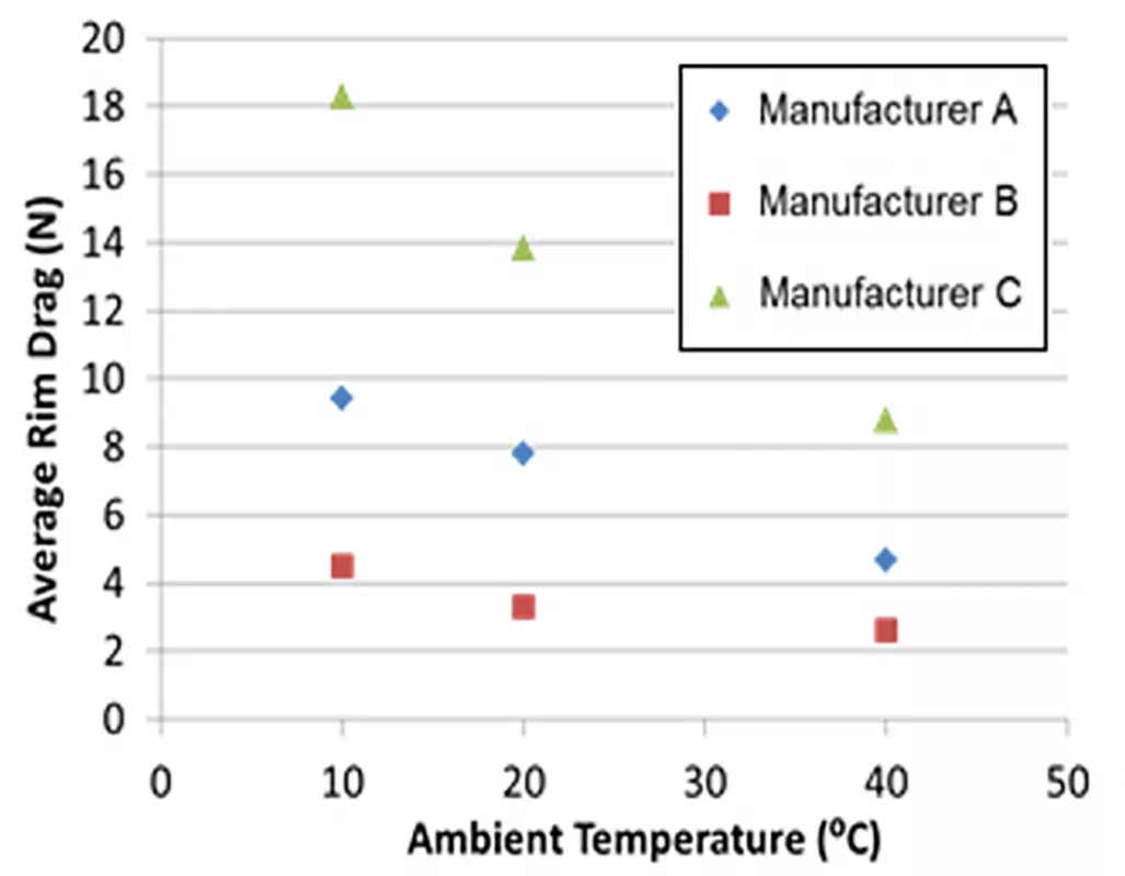
Fig. 6: Idler roller rotating resistance versus temperature – Measured data
|
Lip seal friction and load dependent bearing friction are both considered independent of temperature, while the labyrinth seal and no-load bearing friction are dependent on internal shearing of the grease, and therefore dependent on grease viscosity and thus temperature. Decreasing rotating resistance with increasing temperature is also seen in Figs. 2 and 3.
Figs. 7 and 8 show the relationship between idler roller rotating resistance, speed and load. Lip seal friction and load dependent bearing friction are both considered independent of rotational speed, while the labyrinth seal and no-load bearing friction are dependent on internal shearing of the grease, and therefore dependent on rotational speed. As the name implies, the load dependent bearing friction is the only friction component influenced by radial load, provided induced shaft deflections are not excessive.
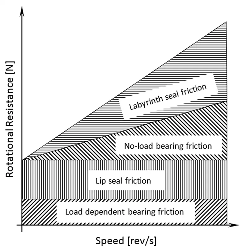
Fig. 7: Idler roller rotating resistance vs speed
|
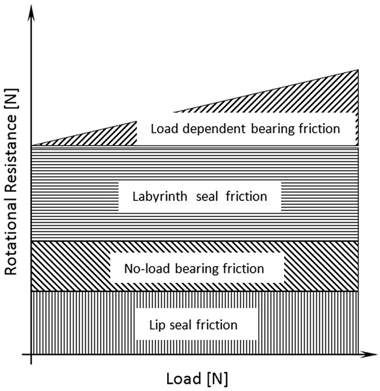
Fig. 8: Idler roller rotating resistance vs radial load
|
While standards provide a quality assurance measure and a means to compare one idler roller to another, acquired data is typically not directly applicable to conveyor design. It is evident from Figs. 5 to 8 that from a design perspective, idler rollers should be tested as a function of ambient temperature (ranging between winter and summer conditions) at the required belt speed and load. If data matching the design parameters are not available, a knowledge of the trends captured in Figs. 5 to 8 in conjunction with the preceding equations can provide an estimate. For example, if data for a single load (typically lower from SANS and DIN standard tests) are available, then the rotating resistance at higher loads can be extrapolated by calculating the additional load dependent bearing friction from Eq. (8). Predicting variations with speed and temperature are more complex, given that the baseline friction due to lip seal friction and no-load bearing friction are unknown. As a minimum, idler roller rotating resistance data should be provided at the rotational speed, and for lower and upper operating temperatures.
The theoretical approximations discussed provide the fundamental theory to not only calculate the rotating resistance, but also to minimise the rotating resistance of the idler rollers at the design stage. Design considerations should include appropriate grease selection for the loading conditions and the temperature range in which the conveyor will be operating, in addition to efficient labyrinth seal design. While the calculated viscous drag of the labyrinth seal is only approximate due to the complicated velocity fields, the theoretical analysis proves instructive for labyrinth seal design. For example, labyrinth seals may be designed efficiently in order to prevent contaminant ingress, but at the same time reduce viscous drag by ensuring small gaps between stationary and rotating surfaces are employed closer to the shaft to reduce torque. Furthermore, gains can also be made by using larger diameter idler rollers to reduce rotational speed and therefore rotating resistance, in addition to the added advantage of increasing the fatigue life of bearings.
While the foregoing analysis has emphasised the benefits of reduced rotating resistance, the reliability of the idler roller is equally important, and careful consideration should also be given to the sealing effectiveness to prevent contamination and premature bearing failure.
3. Conveyor Belt Indentation, Rolling Resistance and Flexure Resistance
Indentation rolling resistance occurs due to the deformation of the pulley side cover of the conveyor belt as it is squeezed between the carcass and successive idler rollers. Belt flexure resistance occurs due to the vertical and transverse displacement of the belt between idler sets. Both resistances to movement of the belt are a result of internal energy losses within the conveyor belt that are absorbed by the belt as heat.
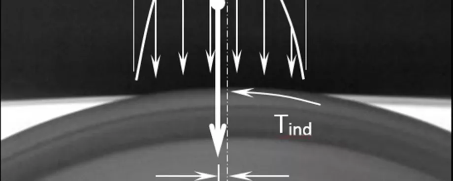
As the rubber belt travels over a conveyor idler roller, the pulley cover is indented by the weight of the belt and bulk material. The indentation cycle involves compression of the pulley cover as the belt drives into the roller, followed by recovery as the belt travels over the roller, as shown in Fig. 9. Since the belt cannot recover at the same rate as it is compressed due to the viscoelastic (time dependent) properties of the rubber, an asymmetric pressure distribution forms, resulting in indentation rolling resistance. Fig. 10 shows the resulting offset pressure distribution that leads to indentation rolling resistance.
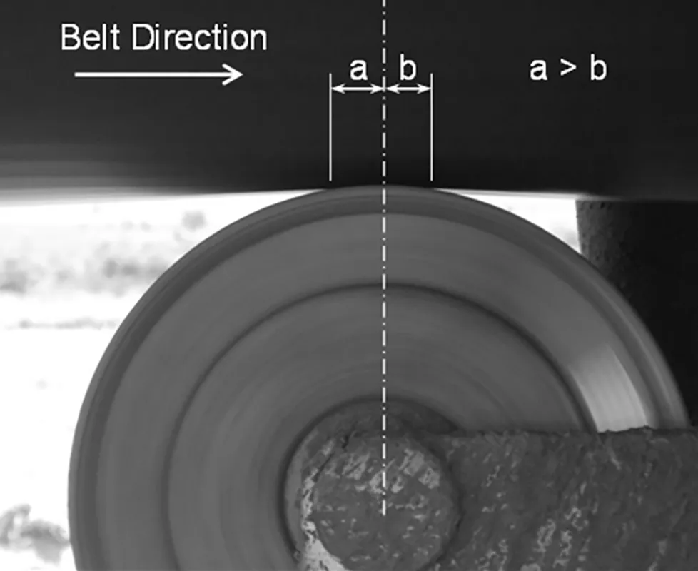
Fig. 9: Indentation rolling resistance – Winker foundation model
|
![Fig. 10: Indentation rolling resistance – finite element model [17]](https://www.bulk-online.com/sites/default/files/public/styles/basic_max/public/2023-12/wp_1255.jpg.webp)
Fig. 10: Indentation rolling resistance – finite element model [17]
|
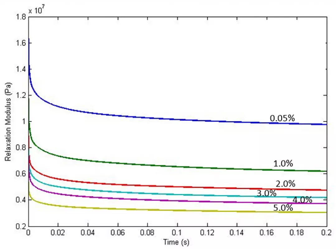
The recovery time of a rubber cover is dependent on the viscoelastic properties of the rubber, and is therefore temperature, belt speed and strain dependent. Fig. 11 shows typical relaxation modulus data for a pulley cover compound tested at varying strain levels.
Flexure resistance of the conveyor belt occurs as a result of the cyclic transverse and longitudinal deflection of the belt between successive idler sets. Longitudinal deflection occurs due to belt sag, while transverse displacement occurs due to the opening and closing of the belt between idler sets. The resulting hysteresis losses in the carcass and carry and pulley covers lead to flexure resistance along the length of the conveyor.
CEMA [12] specifies two general approaches for determining indentation rolling resistance, namely the small sample and large sample methods. In both cases indentation rolling resistance is expressed as a function of normal load for a specific pulley cover compound, idler roller diameter, pulley cover thickness, temperature and belt speed.
3.1 Small Sample Method
The small sample method uses a typical sample size of 3 mm · 12 mm · 30 mm from which the dynamic physical properties of the rubber are measured over a range of temperatures, strains and frequencies. These measurements utilise specialised Dynamic Mechanical Analysis (DMA) equipment and obtain the elastic storage modulus (E’) and loss modulus (E”) of the cover rubber sample. The measured dynamic properties are then used in a range of theoretical approaches to calculate the indentation rolling resistance as a function of normal load, and then based on an assumed loading distribution, used to calculate the indentation rolling resistance per idler set. Fig. 12 shows the basis of a one-dimensional Winkler foundation using a generalised three-parameter Maxwell viscoelastic model, while Fig. 13 shows a finite element approach. In the latter approach the forces acting on each element in the contact zone are calculated to determine the asymmetric pressure distribution acting on the idler roller via the belt.
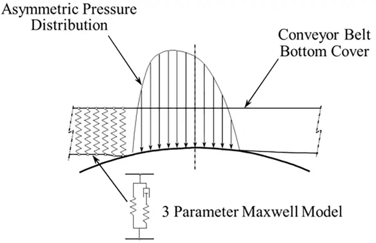
Fig. 12: Indentation rolling resistance – Winker foundation model
|
![Fig. 13: Indentation rolling resistance – finite element model [17]](https://www.bulk-online.com/sites/default/files/public/styles/basic_max/public/2023-12/wp_1252.jpg.webp)
Fig. 13: Indentation rolling resistance – finite element model [17]
|
3.2 Large Sample Method
The large sample method uses a full sample of belt, including the carcass and carry and pulley covers, with specified measurement facilities shown in Figs. 14 and 15. Belts are approximately 400 mm to 600 mm wide, and either 4 800 mm or 29 000 mm long (spliced endless length), depending on the machine. The facility shown in Fig. 15 provides the ability to measure both indentation rolling resistance and conveyor belt flexure resistance. Belt flexure is induced into the sample due to the deformation of the belt by the hold down rollers, with the position of the hold down determined by the belt sag ratio.
Typical data from the large sample test method detailed in Fig. 15 is illustrated in Fig. 16. Indentation rolling resistance versus normal load data is given for a particular pulley cover rubber, idler roller diameter, cover thickness, temperature and belt speed for a range of belt sag ratios.
![Fig. 15: CEMA’s indentation rolling resistance large sample methods – alternate large sample test method (Picture: © CEMA [12])](https://www.bulk-online.com/sites/default/files/public/styles/basic_max/public/2023-12/wp_1251.jpg.webp)
Fig. 15: CEMA’s indentation rolling resistance large sample methods – alternate large sample test method (Picture: © CEMA [12])
|
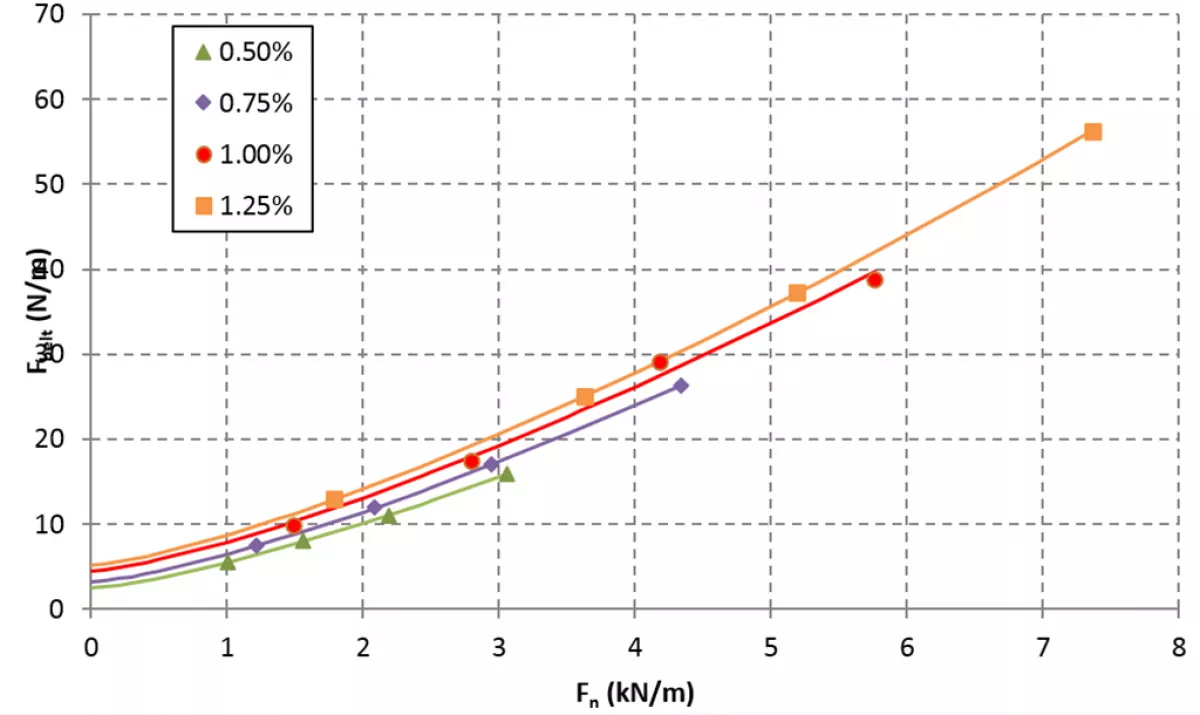
Fig. 16: Indentation rolling resistance and belt flexure resistance versus normal load for a range of belt sag ratios (idler roller dia. = 150 mm, temperature = 40 °C and beltspeed = 4 m/s)
|
In order to differentiate between the belt flexure and indentation rolling resistance components a least squares curve fit of Eq. (14) is performed

|
where I is the y-intercept, I is the multiplier, Fn is the normal force applied to the belt and c is the exponent, where typically c = 4/3.
If tests were conducted without flexing the belt over the measurement idler roller the drag would be purely due to indentation rolling resistance and the experimental data would pass through the origin. The y-intercept is therefore assumed to be attributed to belt flexure resistance resulting in the relationship

|
where

|
and

|
