
3.3 Normal Force Distribution
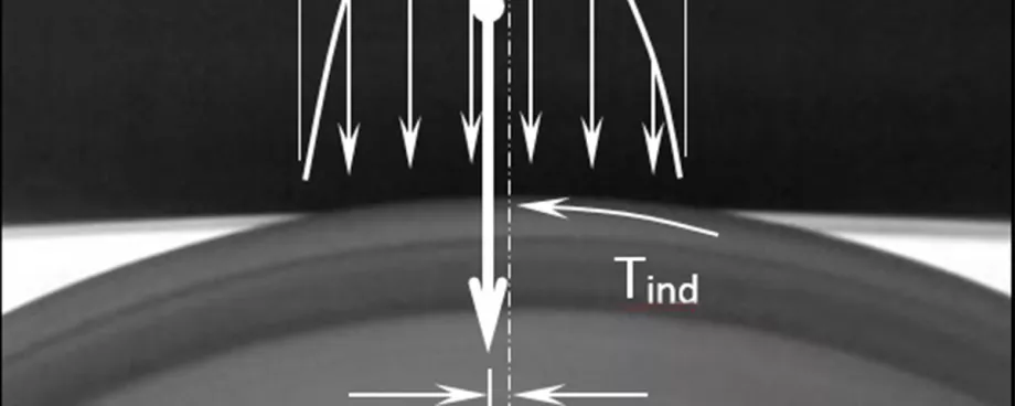
Conveyor belt flexure resistance and indentation rolling resistance are typically measured for a particular belt construction and pulley cover rubber as a function of normal load. To calculate the indentation rolling resistance per idler set it is important to accurately predict the load distribution across the idler set due to the belt and bulk material.

CEMA [12] uses an average pressure distribution between the belt and idler roller based on an equivalent load distribution, while DIN 22123 [13] considers a normalised force distribution, incorporating a constant force distribution for the centre roller and an increasing linear distribution for the side rollers.
For the purpose of this paper the normal force components acting due to the belt and bulk material are shown schematically in Fig. 17. From these forces, the force distribution along the length of the centre and side idler rollers is derived.
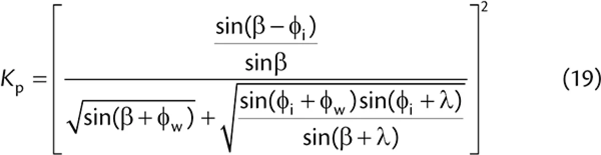
When considering the force distribution across the idler set due to the bulk material it is important to consider the increased loading on the side rollers caused by opening and closing the belt between successive idler sets. The opening and closing occurs following the vertical deflection of the belt. Work in this area was first undertaken by Krause and Hettler [18] who provided an analysis of the total force acting on the idler rollers as a result of the formation of active and passive stress states within the cross-section of the bulk material. The active pressure factor for opening the conveyor belt Ka, is expressed as

|
where φw is the friction angle between the bulk material and the conveyor belt, φi is the internal angle of friction of the bulk material, β is the troughing angle and λ is the conveyor surcharge angle. The passive pressure factor for closing the conveyor belt Kp, is given by
|
Ilic [19] found through a series of laboratory and field experiments that the passive stress state is, in most cases, not fully developed in the bulk material during closing. This is primarily due to the relatively small angle of transverse – opening and closing – belt deflection. On the basis of these findings, a reduction factor, R, was applied to the passive pressure factor, Kp for the closing of the conveyor belt. The factor is dependent on the internal angle of friction of the bulk solid. For free flowing to moderate-to-handle bulk materials with internal angles of friction up to 45°, a value of 0.4 was found to be suitable, while for bulk materials with an internal angle of friction over 45°, a value of 0.2 was selected. The normal force, Fm,ns acting on the inclined side of the belt (side idler rollers) due to the bulk material is therefore

|
where a is the idler spacing, ρ is bulk density, Lm,s is the length of bulk material in contact with the inclined side of the conveyor belt, and the active and passive stress states are assumed to act over half the idler spacing.
The normal force, Fm,nc on the centre idler roller due to the bulk material is equal to the total load of the bulk material acting over the length of the idler spacing, less the vertical components of force exerted on the side rollers.

|
where A is the cross sectional area of bulk solids on the conveyor belt.
In addition to the normal forces generated by the bulk material, the normal forces caused by the weight of the belt must also be considered. The normal force Fb,ns acting on the side idler roller due to the weight of the belt is

|
where Lb,s is the length of belt in contact with the side idler roller, Bw is the belt width and qb is the mass of the belt per unit length. The normal force, Fb,nc acting on the centre roll on account of the weight of the belt is

|
Fig. 17 shows a typical normal force distribution acting across a three-roller idler set and the resulting indentation rolling resistance. As noted in DIN 2123 [13], the normal force distribution can be expressed as

|
where L is the total contact length of the bulk material with the belt and is given by

|
where Lc is the contact length for the centre roller and Lm,s for the side rollers.
The indentation rolling resistance along each idler roller is then derived from Eq. (17) and is given by

|
Figs. 18 and 19 show that the force distribution along the length of the centre roller is constant and is a sum of the force due to the belt qb,c(z) and bulk material qm,c(z), where
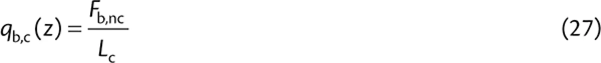
|
and

|
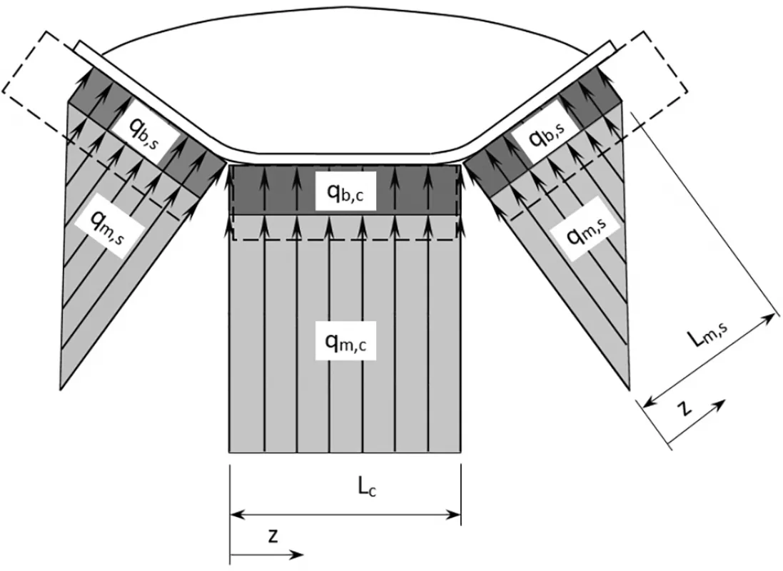
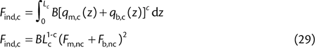
Fig. 18: Normal force distribution and resulting indentation rolling resistance for a three-roller troughing idler set – cross section showing normal force between idler rollers and belt
|
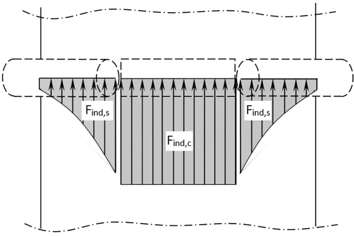
Fig. 19: Normal force distribution and resulting indentation rolling resistance for a three-roller troughing idler set – bottom view showing indentation rolling resistance distribution
|
From Eq. (26), the indention rolling resistance force acting on the centre roll is therefore given by
|
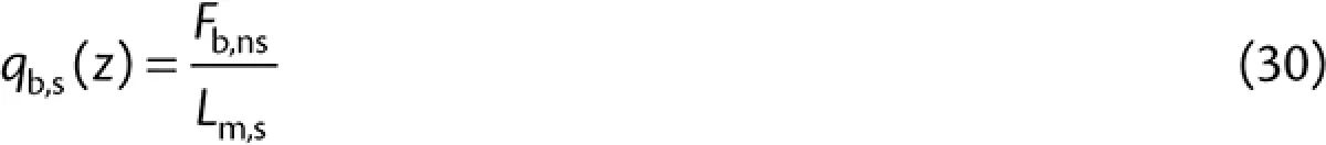
The force distribution along the side idler rollers is a combination of the force as a result of the belt qb,s(z) and a linearly decreasing load due to the bulk material qm,s(z), where
|
Bearing in mind that the force due to the belt weight is assumed to act over the length of contact of the bulk material rather than the belt contact length to simplify the load distribution.
The linearly decreasing force due to the bulk material is given by

|
Therefore

|
The total indentation rolling resistance per idler set is therefore

|
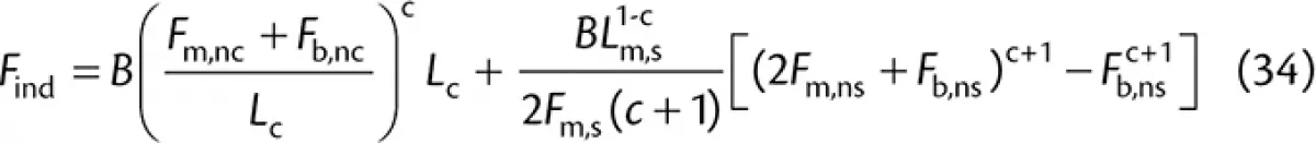
|
where the normal forces are dependent on the belt, idler roller geometry and bulk material properties, the constants B and c are dependent on the measured indentation rolling resistance properties of the belt.
3.4 Design Considerations
The preceding section provided methods to calculate the indentation rolling resistance and belt flexure resistance per idler roller set in terms of load, temperature, idler roller geometry, and bulk material and belt properties. These components were calculated using measured indentation rolling resistance and belt flexure data.
Indentation rolling resistance is dependent on the pulley cover rubber, normal load, temperature, idler roller diameter, cover thickness and belt speed. Indentation rolling resistance is considered independent of belt tension, and therefore belt sag, and is considered to be constant for each idler set along the length of the system. If horizontal and/or vertical curves are present, indentation rolling resistance varies according to the changing load profile.
The energy lost as a consequence of the flexure of the conveyor belt over each idler roller is dependent on the belt construction, temperature, and the extent of flexure which is dependent on the belt tension and longitudinal stiffness. Belt flexure resistance is typically small relative to indentation rolling resistance, although lighter loads and low temperatures can lead to belt flexure being significant. Belt flexure varies along the length of the conveyor due to changes in belt tension, however as this is a relatively small contribution, it can typically be considered constant.
Based on the preceding analysis it is evident the conveyor designer has many options during the design stage to reduce belt flexure and indentation rolling resistance. Some of the more common methods are discussed below.
3.4.1 Low Rolling Resistance Pulley Cover Compounds
Low rolling resistance pulley cover compounds are designed to maximise the energy restored during the recovery cycle. Significant energy savings can be made with the correct selection of pulley cover compound, however several factors should be taken into consideration. When evaluating the use of low rolling resistance compounds it is advisable to analyse potential energy savings over the range of average monthly temperatures as compounds are often temperature dependent [21]; furthermore, compounds that are temperature dependent will also be velocity dependent, and should be tested at the corresponding belt speed. To maximise the benefit of low rolling resistance compounds belt turnovers are typically employed on long belt conveyors to gain advantages on the return side.
3.4.2 Large Diameter Idler Rollers
Large diameter idler rollers have the advantage of reducing the contact stresses at the pulley cover and roller interface, therefore reducing indentation rolling resistance. For the same bearing and seal arrangement, larger idler rollers offer lower rotating resistance as a result of their larger radius. The larger radius also lowers the angular velocity which results in lower viscous resistance from the grease in the bearings and labyrinth seals and further reduces drag. In some cases it has proven more advantageous to utilise larger diameter idler rollers only for the more heavily loaded centre roller (see Fig. 18). Selectively using larger diameter rollers reduces investment cost and limits rotational mass.
3.4.3 Reduced Vertical Load
Reducing the vertical load on the belt reduces indentation rolling resistance. If for example, the load is halved, then from Eq. (17) indentation rolling resistance will decrease by 2c (i.e. 2 to the power of c, where typically c = 4/3) and result in a disproportionate decrease with load [7]. Clearly, any reduction in load requires an increase in belt speed to maintain a constant carrying capacity, which in turn, increases indentation rolling resistance, but at a lower rate.
3.4.4 Increased Idler Spacing
Reducing the number of times a belt is deflected between idler roller sets over the length of a system reduces the total conveyor belt flexure resistance. While this provides energy savings, they are relatively small in comparison to other components, with the most significant benefits of increased idler spacing resulting from reduced bulk material flexure resistance that is discussed Section 4.
3.4.5 Belt Carcass
It has been shown experimentally [7] that fabric reinforced belts exhibit greater indentation rolling resistance than steel cord belts, while steel cord belts with smaller diameter cables exhibit lower indentation rolling resistance than those with large diameter cables. These results prove the belt carcass plays an important role in indentation rolling resistance, and that any model or test should consider the elements and construction of the carcass. Furthermore, the belt carcass significantly influences the longitudinal stiffness of the belt and therefore the belt flexure resistance.
4. Bulk Material Flexure Resistance
Bulk material flexure resistance occurs due to the longitudinal and transverse displacement of the belt and bulk material between successive idler sets and the associated internal friction losses within the bulk material. As mentioned earlier, the belt and bulk material undergo complex interactions as the belt opens and closes transversely and is displaced vertically due to belt sag. The losses associated with the flexure resistance of the bulk material cannot easily be isolated and measured independently of the belt, therefore making this component of the main resistance the most difficult to quantify and accurately predict.
Several researchers have investigated the topic of bulk material flexure resistance. Investigations included analytical approaches [1,12,20], experimental investigations [22], and others have provided combined experimental and numerical methods [6,19]. For simplicity the approach outlined follows the theoretical approach of Spaans [1]. This approach considers the active and passive stress states that the bulk material undergoes as it travels from one idler set to the next. Spaans [1] notes that the bulk material flexure resistance is dominated by the longitudinal deflection, rather than the transverse deflection of the belt. He derives the longitudinal bulk material flexure Fm,flex, as

|
where EI is the flexural rigidity of the conveyor belt, T is the belt tension, φi is the internal angle of friction, h is the average height of bulk material above the centre idler roller, a is the idler spacing, ω = √(T⁄EI) and x is the distance from the idler roller set where the stiff trough-shaped belt transitions into a slack one and where the radius of curvature is smallest. Values of x typically are in the range 0.010 m < x < 0.040 m and are greater with increasing troughing angle, wider belts, greater tension and a stiffer belt carcass.
The relationship derived by Spaans [1] provides an estimate based on measured bulk material and belt properties, rather than relying on empirical approximations. Furthermore, the relationships resulting from Eq. (35) correspond to the more complex numerical solutions and experimental findings [6,19].
4.1 Design Considerations
From Eq. (35) it is evident that the bulk material flexure resistance is heavily dependent on the geometry of the cross-section of bulk material with the flexure resistance increased by the height of bulk material squared. Furthermore, the flexure resistance of the bulk material decreases by the root of the belt tension, meaning less sag results in less belt and bulk material deflection and therefore less resistance.
To consider the coefficient of bulk material flexure resistance, ƒm,flex, Eq. (35) is divided by the sum of the weight of bulk material and belt to give

|
To analyse the influence of bulk material internal friction and idler spacing, Fig. 20 shows results from Eq. (36) for a 1.2 m wide belt with a sag ratio of 1% conveying material with a bulk density of 1000 kg/m3. Several trends are immediately evident, including an increase in the bulk material flexure resistance coefficient with internal angle of friction, and a decrease with increasing idler spacing. In terms of the latter, bulk material flexure resistance per idler set increases with increasing idler roller spacing due to more work being done. However, the work per unit length decreases, resulting in an overall decrease in the bulk material flexure resistance coefficient with increasing idler spacing. In addition, other research [9] has shown the investment cost is typically reduced, since while belting costs increase (due to greater belt strengths), the increased cost is offset by a greater reduction in cost thanks to fewer idler sets.

Fig. 20: Coefficient of bulk material flexure resistance versus internal angle of friction and sag ratio (belt width = 1.2 m, bulk density = 1000 kg/m3) – sag ratio = 1%
|

Fig. 21: Coefficient of bulk material flexure resistance versus internal angle of friction and sag ratio (belt width = 1.2 m, bulk density = 1000 kg/m3) – internal angle of friction = 35°
|
Fig. 21 shows the bulk material flexure resistance coefficient versus sag ratio for a 1.2 m wide belt, a bulk material density of 1000 kg/m3 and an internal angle of friction of 35°. As expected, the bulk material flexure resistance coefficient increases with increasing belt sag ratio due to greater work from the increased vertical displacement of the bulk material.
In general, wider carry side idler roller spacing and higher belt tensions reduce bulk material flexure resistance, while bulk materials with greater internal friction generate more bulk material flexure. Likewise, wider idler roller spacing has the added advantage of less rollers and frames, usually with a resulting decrease in investment cost.
5. Conclusion
This paper has presented a combination of theoretical models and measured data to assist in the design of energy efficient belt conveyors. A number of theoretical models to predict the main resistances of belt conveyors have been discussed with reference to testing standards and handbook methods. Through a comprehensive analysis of the motion resistances, key design parameters for energy efficient conveyor design were identified, enabling designers to select a combination of parameters that result in cost effective energy efficient solutions.
■