
(From the archive of ”bulk solids handlingshowthread.php?32098 About the bulk solids handling journal and this archive", article published in Vol. 36 (2016) No. 6 , ©2016 bulk-online.com)
Introduction
In the mining industries the storage of bulk solids in large quantities is often achieved through the use of open stockpiles in which the reclaim is by gravity flow through hoppers, feeders and/or chutes onto reclaim conveyors installed below ground level. In many cases the load-out conveyor supplying the bulk solid to the stockpile is via a boom conveyor supported by a vertical support structure located outside the peripheral area of the of the stockpile rill zone at ground level. The support structure is not in contact with the stored stockpile material.
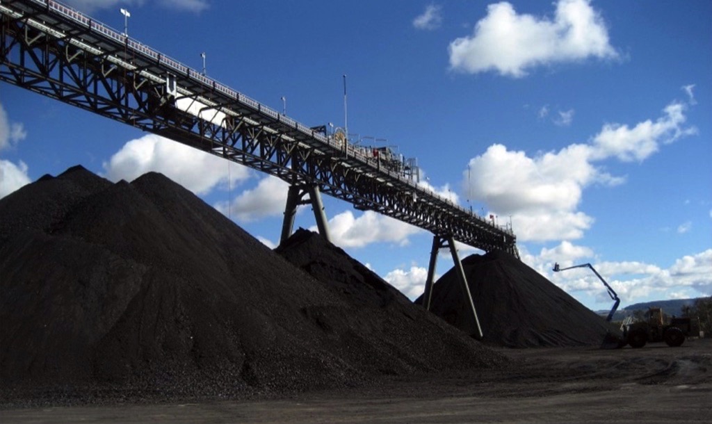
In other cases, particularly in the coal industry, the load-out conveyor is supported on trestle legs which are substantially buried in the stockpile as illustrated in Fig. 1. It is this system that is the subject of this paper. The paper builds upon the work of Roberts et al [1-3] which dealt with buried structural members which are square or rectangular in cross-section. In this current study, the trestle legs are hollow tubes of circular cross section which required the load theory to be appropriately modifiedAs stated by Roberts [1], the loads acting on the trestle legs are quite complex and variable, being dependent on the following conditions:
- Variations in the flow properties of the material
- Loading and unloading history and mechanism for loading and unloading
- Slumping and avalanching during periods of heavy rain
- Length of time the bulk material remains undisturbed in the stockpile
- Degree of load support provided by the consolidation of the bulk solids acting around the trestle legs
- Rigidity of the stockpile base - whether any ground settlement has occurred
- Variations in stress fields from active to passive during filling and reclaim
For these reasons, it is recommended that a conservative approach be taken to the trestle leg load calculations.For the efficient operation of the storage and load-out system, it is important that the stockpile geometry and the positioning of the reclaim hoppers and feeders be such that the tonnage of bulk solids reclaimed by gravity flow is achieved. Procedures for achieving this objective are presented by Roberts et al [4,5].
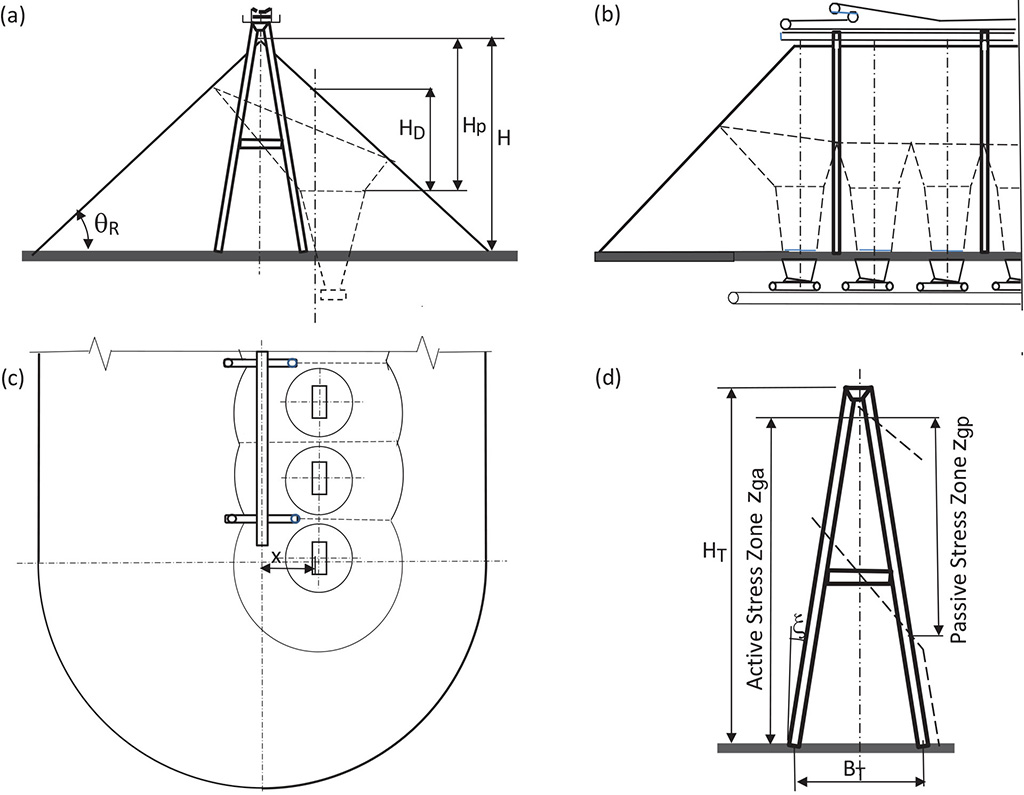
Reference to Fig. 2 shows that the reclaim hoppers, feeders and conveyor are offset an amount defined by “x” from the centre of the stockpile. This is deliberate. Since the reclaim volume is controlled by the draw-down HD measured from the free surface of the pile, it can be shown that the improvement in live capacity is possible over that achieved by locating the reclaim centrally. Furthermore, the offset reclaim assists the layout for the central positioning of the loads-out conveyor and its trestle leg supports.
1. Loading Conditions on Trestle Legs
In general, the principal loads are those due to the variation of the normal pressures with depth during the filling and reclaim processes, and the non-uniformity or eccentricity of these pressures acting around the periphery of the trestle legs. The combination of these pressure variations gives rise to bending stresses in the support trestle legs. Furthermore, the cumulative, in-plane type compressive loads due to the shear stresses acting downward along the trestle legs can contribute to the buckling loads, thus exacerbating the lateral bending.Referring to Fig. 2, it is assumed that the stockpile is filled to its maximum height so that the trestle leg structures are fully immersed in the coal with the highest loads occurring on the side of the legs nearest the tripper position during filling operation and on the side of the legs furthest from the reclaim openings during discharge. In view of its relevance to the present study, the original theory of Roberts [1] is reviewed.
1.1 Loading Process – Active Stress State
The trestle leg loads for the active case are depicted in Fig. 3. As the bulk solid is discharged from the loadout conveyor, it slides down the sloping surface of the pile as it is formed, coming to rest with the surface inclined at the angle of repose θR of the bulk solid. Within the stored mass, as the depth z increases, the bulk solid continues to move by internal shear at a steeper angle. In this case the slope angle measured from the horizontal approaches that of the effective angle of internal friction δ. For this condition the angle β of Fig. 3 is such that β = (90° - δ).
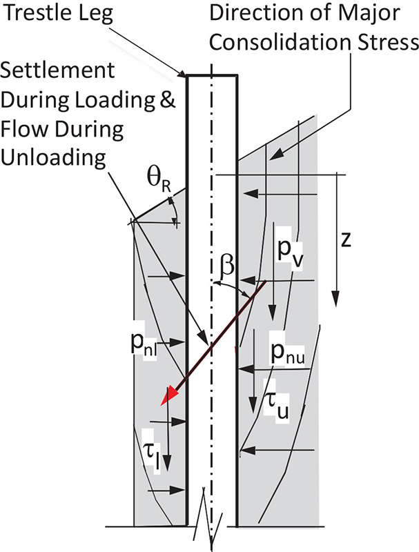
Internal creep due to shear continues for some time after the stockpile is loaded. Depending on the stockpile capacity and the properties of the bulk solid, creep may continue for several hours or even longer periods as the bulk solid approaches, asymptotically, its critical consolidation condition. While this movement is not normally observable being incrementally small as time increases, nonetheless is does occur. The loading condition is said to be “active” since the major principal consolidating stress acts more in the steeply inclined direction as illustrated in Fig. 3. For cohesive bulk solids, it is also known that the internal creep delays the backfilling of the trestle legs resulting in lower stress levels and, hence, lower support provided by the bulk solid in contact with the trestle legs.
1.2 Load Condition – Passive State of Stress
During storage and reclaim, a “passive” stress state, illustrated in Fig. 4, may be established in the region of the trestle legs. For the storage or filling phase, a passive stress state is possible due to
- settlement during storage,
- lateral deflection due to bending of the trestle legs.
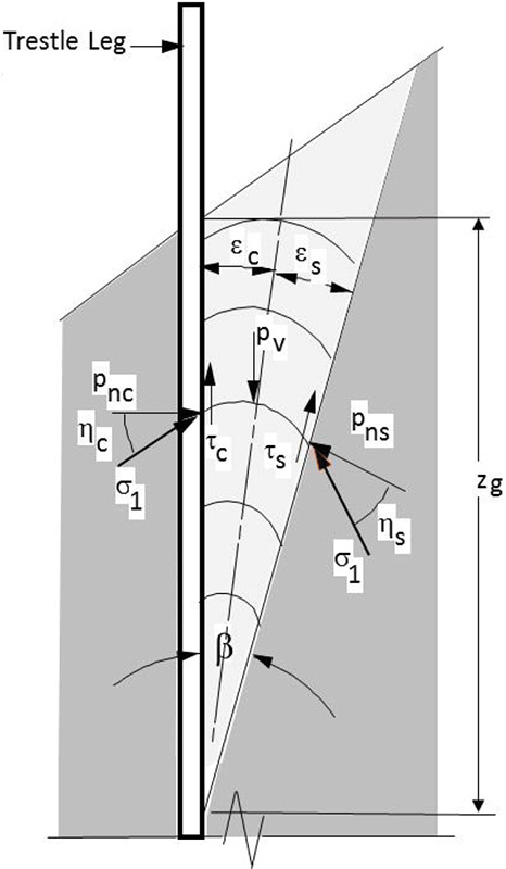
For the reclaim, gravity flow phase, a passive state of stress occurs with a wedged-shaped flow convergence arising as a result of downward movement during flow. This gives rise to an arching condition in which the major consolidating stresses are more in the lateral direction tangential to the arches.It is assumed that the shear boundary defined by the angle β gives rise to the wedge loading condition as illustrated. The centre line of the wedge is defined by the angles αc and αs which depend on the friction at the column surface and the internal shear surface respectively. It is noted that αc + αs = β.
2. Trestle Leg Load Analysis Model
The model for the trestle leg load analysis for both the active and passive cases is shown in Fig. 5. The dimension zg defines the depth applicable to the relevant stress field. This dimension, in general, will be different for the active and passive cases. The load analysis model for the pressure and load distribution around the trestle leg is shown in Fig. 6.
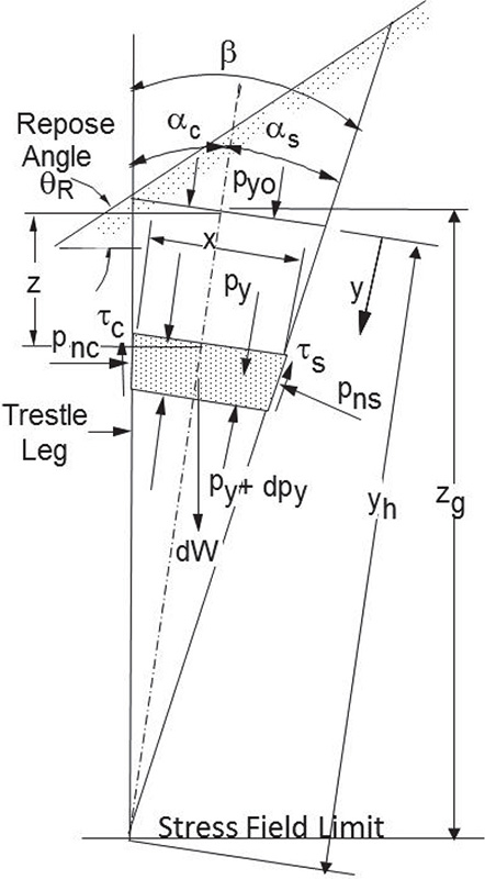 Fig. 5: Load analysis model
|
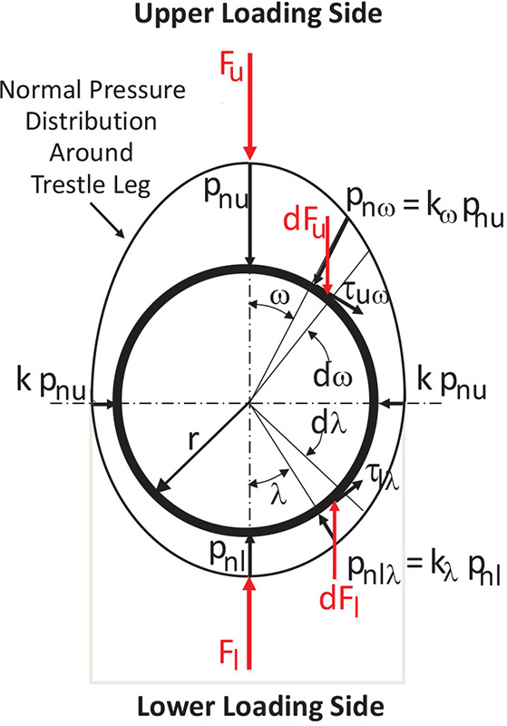 Fig. 6: Pressure distributions and loads
|
Referring to Fig. 5 and choosing the coordinates “x” and “y”, the equilibrium analysis of the elemental slice of thickness dy leads to the following differential equation:
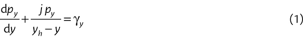 |
The solution of this equation for the pressure distribution is
 |
with
and
whereγ = bulk specific weight, (kN/m3);φw = wall friction angle for column surfaceδ = effective angle of internal friction;pyo = surcharge pressure; y = z (cos αc)-1
2.1 Active Case
Based on the discussion in Section 1.1, the angle β = (90° - δ) For the active loading condition it is reasonable to assume thatαc = αs = β/2 for which the pressure ratios, Kc = Kca and Ks = Ksa, are given by
and
The analysis assumes that on the slip plane the coefficient of internal friction corresponds to the maximum shear stress. Hence,
whereφwi = equivalent internal friction angleThe parameter ‘j’ in Eqs. (4) and (5) allows for the degree of compressibility of the bulk solid and the rigidity of the stockpile base. In this case, it is assumed that 0 ≤ j ≤ 0.2. The maximum limiting case for the pressure py occurs when j = 0 for which the pressures py, pv, pnc and pns are ‘hydrostatic’, increasing linearly with depth as follows:
and
as well as
and
2.2 Passive Case
In this case the stress field is as shown in Fig. 5 with the angle b of the failure plane defined as β = 45° - δ/2.It is assumed that failure on the slip plane occurs at the maximum shear stress. Eq. (2) applies in this case with the pressure ratios Kc = Kcp and Ks = Ksp which need to be selected in accordance with passive stress field model.Two methods are considered for the determination of these stress ratios, one based on the Australian Standard AS3774 on “Loads in Bulk Solids Containers” [6], and the other a modified version of the AS3774 method. In accepting that the flow in the region of the trestle legs is a complex mixtures of axi-symmetric and plane flow, it is reasonable to assume plane flow is the dominant mode of flow.
2.2.1 Method based on AS3774
In this case the relationships for the K values are given by
and
where
and
2.2.2 Modified Method
Experience in hopper design has shown the AS3774 method sometimes under-estimates the wall loads in plane flow hoppers. This has led to the modified pressure ratios as follows:
2.3 Support Loads on Rear Lower Face of Columns
As previously discussed, the back-pressure support against lateral deflection of the trestle legs is uncertain and, generally during filling and reclaim, will be of low order, particularly in the case of cohesive bulk solids. The most conservative approach is to assume that the pressure pnl (Figs. 2 and 4) is zero. However, it is suggested that a more reasonable approach is to calculated the back pressure as follows:
and
It may be shown that the ratio of normal to vertical stress, kcr, is given by
This equation corresponds to that given in Section 6.2.1.1 of AS3774 [6]. In this paper, for example, the values δ = 50° and φw = 30° are assumed as being relevant for the coal stored in the stockpile.Applying Eq. (19) gives kcr = 0.14. It is noted that AS3774 adopts the lower bound value pressure ratio of 0.35 for the active stress state for the wall load determination in cylindrical bins and silos. When extrapolating this information to the stockpile trestle leg loads, it is contended that the lower value of kcr calculated using Eq. (19) is relevant so as to avoid over-estimating the lateral support by coal on the rear or backfilling face of the trestle legs.
2.4 Pressure Distribution around Trestle Leg and corresponding Loads
Referring to Fig. 5, the pressure pnu is the peak pressure as determined in accordance with Sections 3.1 and 3.2 for the active and passive cases respectively.
2.4.1 Upper or Loading Half of Trestle Leg
At an arbitrary position define by the angle ω, the normal pressure is defined by
where kω is expressed by
such that 0.35 ≤ k ≤ 1.0It is noted that for the lower bound value of k = 0.35, kω = 1 for ω = 0, and k = 0.35 when kω = π/2. It is assumed there is some build-up of bulk solid on the trestle surface, so that the friction coefficient μi defining the shear stress τ is given by Eq. (6). The elemental force per unit length dFu is given by
The total force Fu per unit length is given by
which becomes
where De is the effective trestle leg diameter and is given by
and
with r = outside radius of trestle leg.The recommended lower bound value is k = 0.35, which, for d = 50°, gives C = 1.05 and De = 1.05 . D, where D = 2 . r = actual trestle leg outside diameter. The value k = 1.0 corresponds to the pressure pnu being constant around the upper loading half of the trestle leg. For this maximum or upper bound case, C = 1.7, for which De = 1.7 . D.
2.4.2 Backfilling Half of Trestle Leg
This is determined in a similar way to the above. In this case, when λ = 0, kω = kn as defined by Eq. (19).
2.5 Effective Trestle Leg Diameter for Load Calculations
It is noted that AS3774 recommends that the load calculations for buried structural elements be based on the projected area corresponding to De = 2 · D. The Standard seems to be referring more to horizontal or lateral support tie beams in hoppers and silos rather than vertical or steeply inclined support legs buried in stockpiles. It then becomes a value judgement as to whether the factor of 2 should be applied in the case of the trestle leg loads. It needs to be noted that, over a period of time, progressive adhesion and build up may occur around the trestle legs, thus increasing the effective diameter.This is more likely in the case of bulk materials exhibiting a high level of cohesion. If this is a distinct likelihood, then the conservative approach is to select De = 2 · D. On the other hand, the analysis presented in Section 2.4.1 above shows that the lower and upper bound values to be C = 1.05 and C = 1.7, respectively. Weighing up the various factors, the recommended lower limit is C = 1.2.
2.6 Trestle Leg Compressive Loads
The vertical shear stresses acting along the column faces give rise to compressive loads which increases down the column. At an arbitrary depth location, z, corresponding to coordinate y, the vertical shear stress on the column face is given by
where K = Kc for the active case and K = Kcp for the passive caseAt depth z, the cumulative compressive force per metre of trestle leg circumference is given by
Noting that the vertical pressure py is given by Eq. (2), then substituting for py in (26), for τz in Eq. (27) then integrating gives the following expression for the compressive force per unit circumference,
where
and
with μ1 = tan φw which allows for some build-up of bulk solid on the trestle leg surfaces, and Fzo = surcharge load on each leg due to the weight of the conveyor, its load and the support structure.While the normal stress and corresponding shear stress will vary around the leg circumference as illustrated in Fig. 6, it is recommended that the conservative approach for the compressive loads be adopted by assuming the normal and stresses are the maximum values uniformly distributed around the periphery of the leg.
3. Trestle Leg Design Example
A particular case of the load-out coal stockpile and reclaim system of Fig. 2 is now considered. The relevant details are as follows
- Stockpile height fully loaded Hs = 32 m
- Trestle leg height HT = 34 m
- Trestle leg slope angle ε = 10°
- Leg spacing BT = 12 m
- Leg diameter D = 1.2 m
- Active stress zone zga = 31 m
- Passive stress zone zgp = 22.4 m
- Reclaim hopper offset X = 7 m
- Angle of repose θR = 38°
- Bulk density of coal ρ = 1.0 t/m3
- Trestle friction angle φs = 30°
- Static internal friction φt = 40°
- Effective internal friction angle δ = 50°
Relevant results are presented in Figs. 7 to 10. Fig. 7 shows the normal pressures for the active and passive states for the upper loading face and rear and backfilling face. The corresponding net normal pressures acting on the loading faces of the trestle legs are shown in Fig. 8. These pressures are used to calculate the corresponding loads in accordance with Sections 2.4 and 2.5. Fig. 9 shows the circumferential normal pressure distributions around the trestle legs at critical levels for the passive case at the depth 8.3 m and for the active case at the depth of 27 m. For the active case, the parameter j = 0.2 is assumed. Fig. 10 shows the compressive loads per metre of circumference acting on the trestle legs.
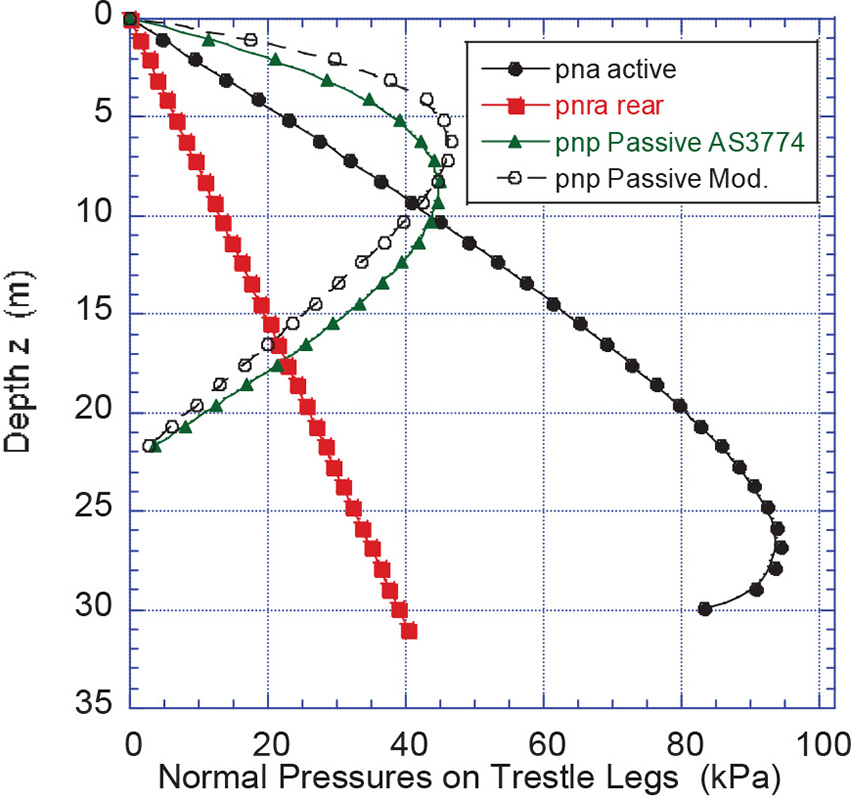 Fig. 7: Normal pressures on trestle legs
|
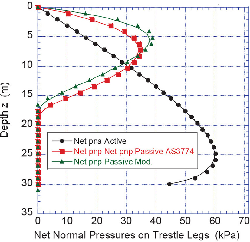 Fig. 8: Net normal pressures on trestle legs
|
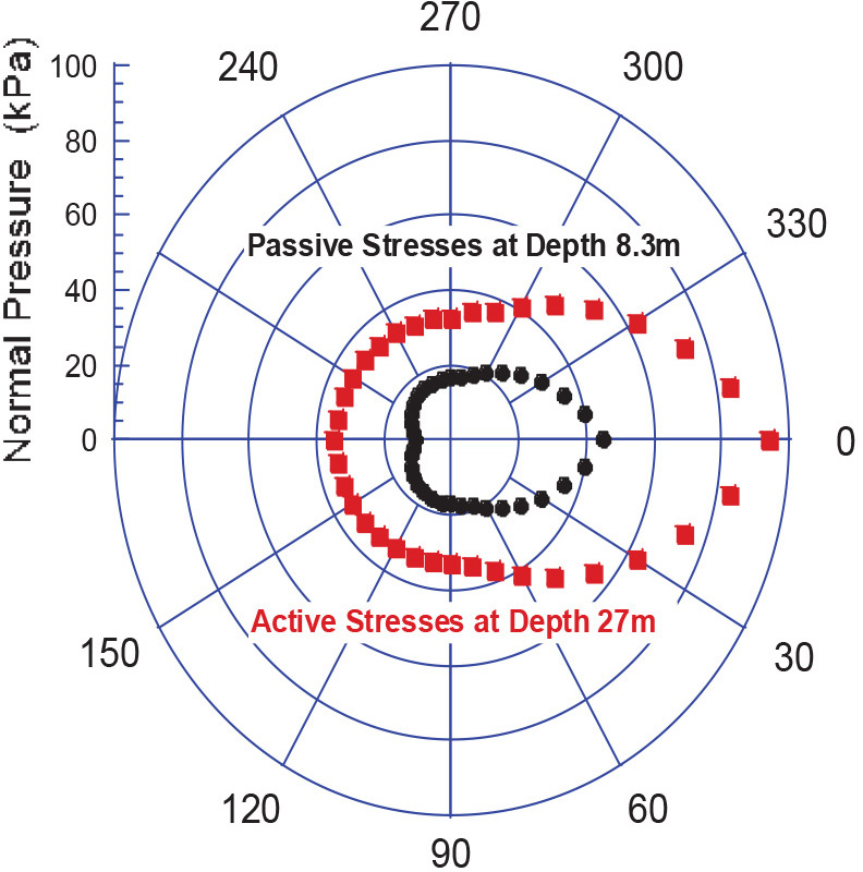 Fig. 9: Circumferential pressures distribution
|
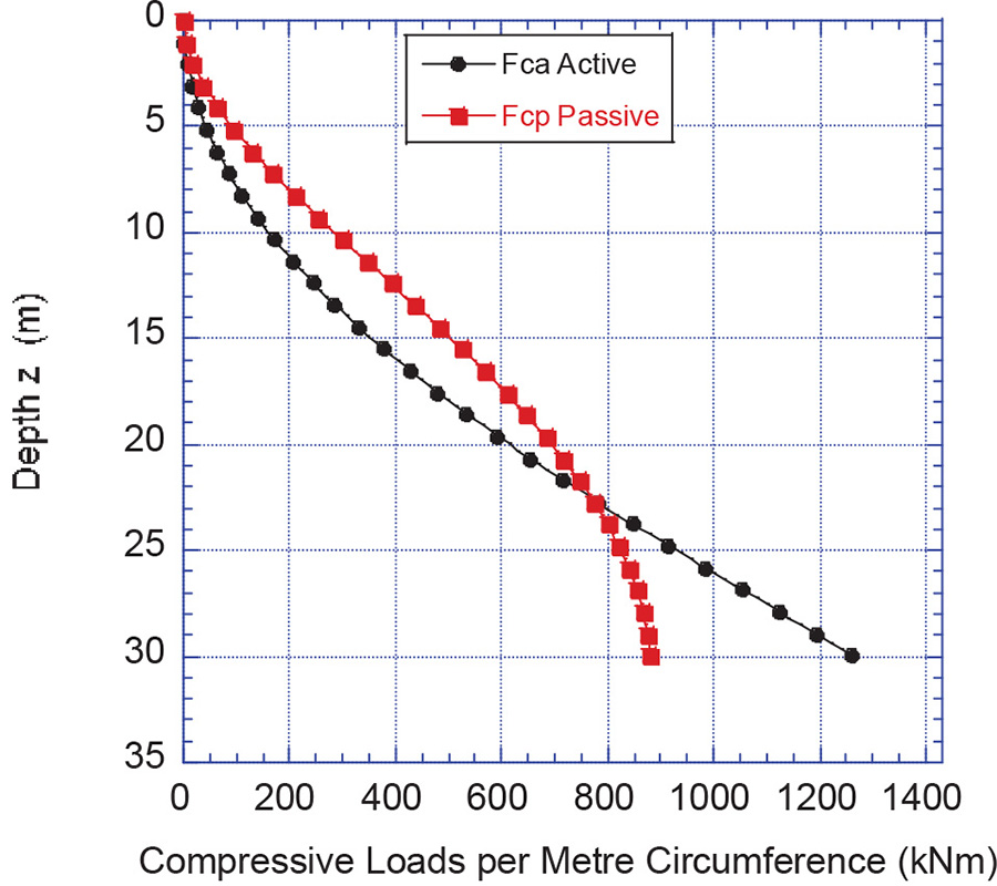 Fig. 10: Compressive loads per meter circumference
|
4. Concluding Remarks
The loading conditions experienced in conveyor support trestles buried in coal stockpiles are both complex and variable. The loads are a combination of lateral loads due to filling and reclaim and in-plane compressive loads due to the draw-down forces. The magnitude and distribution of the loads over the trestle leg faces depend very much on the properties of the coal and the manner in which the stockpile is formed and reclaimed. The loads result from an active stress state during filling and from a passive stress state during reclaim. The degree of lateral support due to the backfilling is quite uncertain and should be ignored if there is any doubt as to the possible level of support that is provided.It is important that the compressive forces in the buried trestle legs due to the cumulated shear or traction forces acting downward around the leg surfaces be taken into consideration. These forces contribute to the compressive buckling loads in the legs by adding to the compressive structural loads that exist in supporting the load-out conveyor.Due to the uncertainty of the loading conditions, it is important that a conservative approach be adopted in the design. It is also important to note that any loads due to mobile equipment working on the stockpile, as well as dynamic effects, slumping and possible avalanching due to high increases in moisture are not included in the loads determined herein.This paper is part of ongoing research into the subject of loads on buried structures. Follow up research is currently being undertaking through the integration of DEM and FEA analysis of the trestle leg loads. The results of this follow-up work will be correlated with the predictions of the continuum mechanics approach described in this paper with a view to establishing a reliable design methodology for predicting the loads in trestle leg structures.
Acknowledgement:
This article is based on a presentation of the authors during ICBMH2016, 11.-14. July 2016 in Darwin, Northern Territory, Australia.
References:
- Roberts, A.W.: Loads on Support Structural Elements Buried in Stockpiles. Particle and Particle Systems Characterisation 24,( 2007) pp. 352-359
- Katterfeld, A. and Roberts, A.W.: Loads on Buried Structural Elements During Stockpile Filling and Reclaim; Bulk Solids and Powder Science and Technology, Vol. 4, (2009) pp. 15-22
- He, Y, Roberts, A.W., Prigge, J.D. and Jones, M.G.: Pressures on the Support Columns Buried in Iron Ore Stockpiles; Powder Technology (2014), pp 358-369http://dx.doi.org/10/1016/j.powtec,2014.03.044
- Roberts, A.W.: Characterisation for Hopper and Stockpile Design; in D. McGlinchey (Ed.): Characterisation of Bulk Solids, Chapter 3, pp. 85-131; Blackwell Publishing, 2005.
- Roberts, A.W., Wiche, S.J. and Krull, T.: Review of Funnel-Flow Theory in Relation to Draw-Down and Live Capacity of Gravity Reclaim Stockpiles; Bulk Solids and Powder Science and Technology, Vol. 3 (2008), No. 2, pp. 97-107.
- AS3774, Loads on Bulk Solids Containers; Standards Association of Australia, 1996.
| About the Authors | |
 Bin ChenDr Bin Chen is a Consulting Engineer at TUNRA Bulk Solids. He has over 10 years consulting and research experience in bulk solids handling, which has involved a combination of design and evaluation, theoretical modelling, CFD and DEM. His activities have covered a broad area of bulk materials handling design and consultancy, e.g. transfer chutes, silos/hoppers, feeders, train loadout systems, stackers and reclaimers, ship loading/unloading systems, and prediction of silo wall loads and quaking.TUNRA Bulk Solids Research AssociatesThe University of Newcastle, Australia Bin ChenDr Bin Chen is a Consulting Engineer at TUNRA Bulk Solids. He has over 10 years consulting and research experience in bulk solids handling, which has involved a combination of design and evaluation, theoretical modelling, CFD and DEM. His activities have covered a broad area of bulk materials handling design and consultancy, e.g. transfer chutes, silos/hoppers, feeders, train loadout systems, stackers and reclaimers, ship loading/unloading systems, and prediction of silo wall loads and quaking.TUNRA Bulk Solids Research AssociatesThe University of Newcastle, Australia |
|
 Tim DonohueDr Tim Donohue is Engineering Manager with TUNRA Bulk Solids. He has completed a big number of projects in the materials handling field, with transfer chute design and passive dust control research being particularly important and current areas of expertise. Through both research and consulting projects he has become proficient with Discrete Element Modeling (DEM) as well as Computational Fluid Dynamics (CFD) software, and he utilises them in solving industrial problems.TUNRA Bulk Solids Research AssociatesThe University of Newcastle, Australia Tim DonohueDr Tim Donohue is Engineering Manager with TUNRA Bulk Solids. He has completed a big number of projects in the materials handling field, with transfer chute design and passive dust control research being particularly important and current areas of expertise. Through both research and consulting projects he has become proficient with Discrete Element Modeling (DEM) as well as Computational Fluid Dynamics (CFD) software, and he utilises them in solving industrial problems.TUNRA Bulk Solids Research AssociatesThe University of Newcastle, Australia |
|
 Paul MunzenbergerDr Paul Munzenberger is research and consulting engineer at TUNRA Bulk Solids. After completing an apprenticeship as a Fitter Machinist he spent several years maintaining and repairing belt conveyors and other coal handling and preparation equipment. He completed his Bachelor’s Degree in Mechanical Engineering at the University of Newcastle in 2007 with first class honours; he then assumed his position. In parallel he commenced part-time study for a PhD in Mechanical Engineering in the field of belt conveying technology, finalised in 2017.TUNRA Bulk Solids Research AssociatesThe University of Newcastle, Australia Paul MunzenbergerDr Paul Munzenberger is research and consulting engineer at TUNRA Bulk Solids. After completing an apprenticeship as a Fitter Machinist he spent several years maintaining and repairing belt conveyors and other coal handling and preparation equipment. He completed his Bachelor’s Degree in Mechanical Engineering at the University of Newcastle in 2007 with first class honours; he then assumed his position. In parallel he commenced part-time study for a PhD in Mechanical Engineering in the field of belt conveying technology, finalised in 2017.TUNRA Bulk Solids Research AssociatesThe University of Newcastle, Australia |
|
 Alan W. RobertsEmeritus Professor Alan Roberts AM has an outstanding international reputation as a world authority in the field of bulk solids handling. He has a proven international track record in fundamental and applied research, and is highly respected by industry worldwide. He was the founder of TUNRA Bulk Solids in 1975. His contribution to research and consulting spans a period of 50 years and covers almost all aspects in the field of bulk solids handling.TUNRA Bulk Solids Research AssociatesThe University of Newcastle, Australia Alan W. RobertsEmeritus Professor Alan Roberts AM has an outstanding international reputation as a world authority in the field of bulk solids handling. He has a proven international track record in fundamental and applied research, and is highly respected by industry worldwide. He was the founder of TUNRA Bulk Solids in 1975. His contribution to research and consulting spans a period of 50 years and covers almost all aspects in the field of bulk solids handling.TUNRA Bulk Solids Research AssociatesThe University of Newcastle, Australia |
■
