
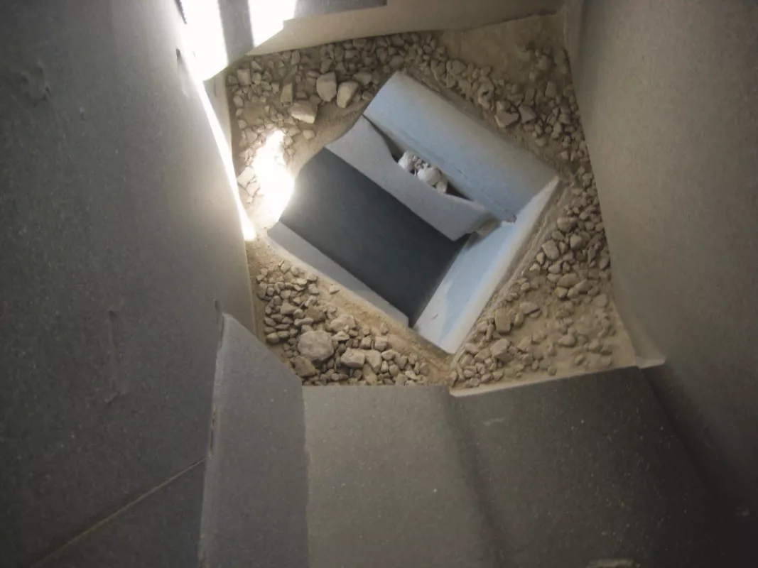
A4 kg (8 lb, 13 oz) piece of limestone dropped from a height of 6 m (20 ft) will hit the pavement at 10 m/s (25 mph). Depending on how the rock lands, either it breaks apart and shoots various sized fragments in all directions, or it remains largely intact and damages whatever it hits.
If that rock is accompanied by hundreds more like it and dropped onto an unprotected conveyor belt every few seconds, an operator can expect an inevitable outcome: fugitive material, persistent breakdowns and costly repairs of the belt, idlers and pulleys.
That’s the situation Martin Marietta found on the B-06 conveyor when the company merged with Texas Industries (TXI) — the largest cement producer in the state — and took over operations of the Hunter Cement facility in New Braunfels, Texas in 2014.
Built in 1979 as a single kiln cement facility producing approx. 0.9 Mt of cement per year, the company added another, larger 1.4 Mt kiln in 2012, more than doubling the site’s production to 2.3 Mtpa. However, Martin Marietta discovered there were some systemic problems that hindered the plant from consistently operating at full production.
Following the handover of operations, the company assigned Reliability Engineer, Rajeshwar Rao Akula, to identify production problems, analyze causes and offer recommendations with action items. Upon inspection he found that one of the major issues was on the B-06 conveyor, which transported crushed limestone from the storage dome to both kilns through an underground tunnel. Akula determined that the main transfer point for B-06 was not able to sustain the force, weight and volume being fed to it, leading to a number of belt and component problems and causing excessive downtime. After presenting his report, company officials agreed on his recommendation to invite Martin Engineering to provide a solution, having already established a positive relationship with the company due to the use of hundreds of Martin Engineering Air Cannons placed throughout the plant.
In Need of a Doctor
The B-06 conveyor is an essential bulk material transport artery. According to Akula, having problems so early in the production cycle impacts operations across the entire facility. “We were experiencing ongoing issues with spillage, broken idlers and belt damage causing downtime that could last for hours,” he explained. “Every week, the system was shut down and a team of 3 to 4 workers would take the better part of a shift to go in with shovels and wheelbarrows to dig the system out to keep it operational. Add to that a belt replacement every six months, and it became a costly mess.”
The Hunter Cement facility has a large quarry that extracts limestone and sends it to a 60 000 t storage dome, which is over 97.5 m (320 ft) in diameter, roughly the length of a football field. From there, approx. 317.5 to 362.8 t/h (350 to 400 st/h) of limestone is loaded into a crusher that breaks down the rock to a size of -203 mm (-8 inch) minus in diameter, then deposits the material into a chute with a 6 m (20 ft) drop onto a 1066 mm (46 in) conveyor belt. The limestone is then conveyed at 1.93 m/s (380 fpm) at a 35-degree incline for 48 m (150 ft) through the tunnel and 48 m (150 ft) in open air, where it is transferred and directed to the proper kiln to be mixed, heated and processed.
Jonathan Cole, Lead Service Technician for Martin Engineering assigned to the Hunter facility, inspected the system and helped issue recommendations, along with overseeing the installation of improvements.
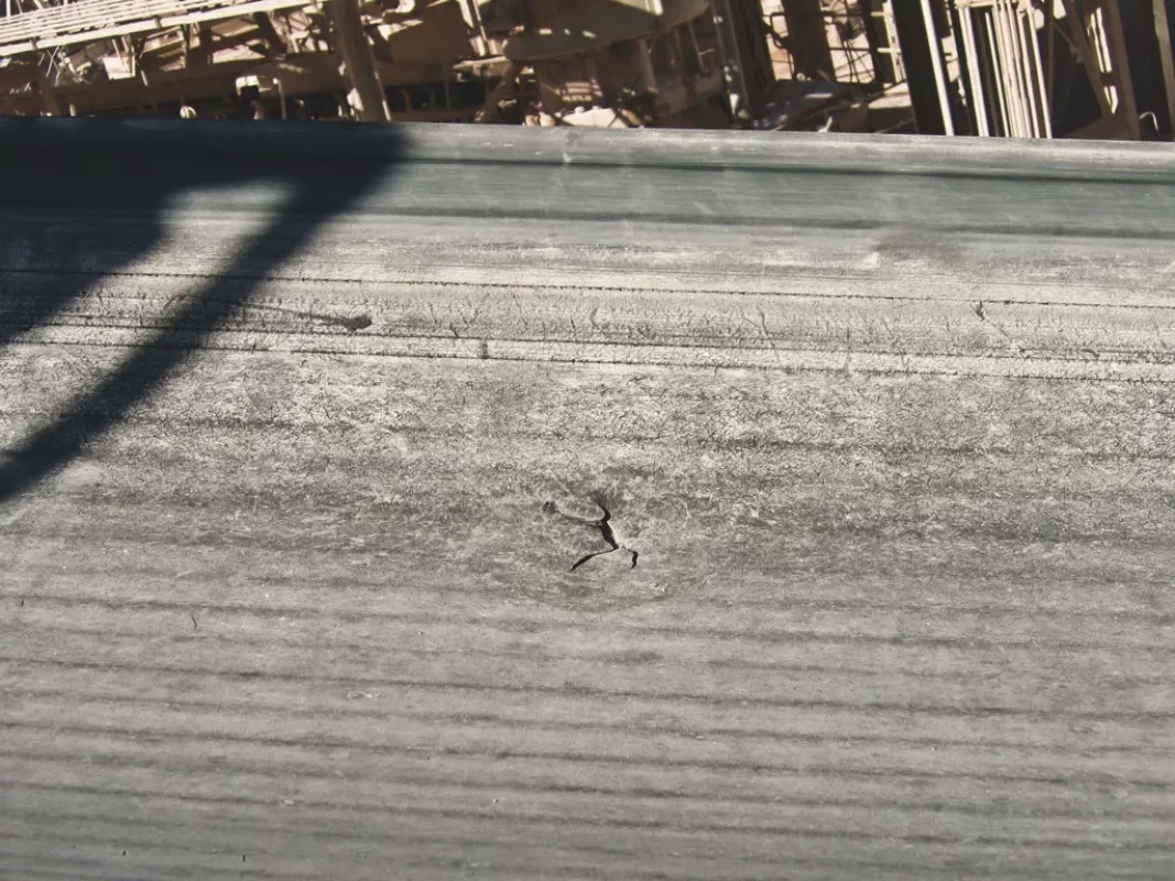
According to Cole, the problems began with the crusher, but extended along the conveyor and through the tunnel. “The crusher was producing -8 in, but the conveyor was only built to handle -4 in,” Cole observed. “The impact from the 20 ft drop blew out idlers and gouged the belt, causing misalignment and extensive spillage.”
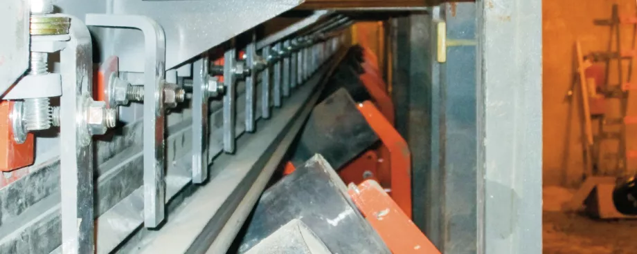
The loads of limestone would land on the fast-moving belt with such force that it often bent or cracked idlers and caused material to bounce, denting and scraping the skirt before it settled. Without being centered, the load would throw the belt off track and continue to shift throughout the transport process. This caused dust and fines to escape from the belt and pile along the conveyor’s frame, clogging the maintenance walkway and obstructing access to the load zone.
Buildup around the frame also deposited jagged carryback material onto the topside of the belt’s return path. The material would get caught in between the belt and tail pulley, gouging both, only to be thrown back onto the belt to make several more trips through, inflicting further damage. These blemishes contributed further to low conveyor performance and belt drift.
Workers frequently inspected the system, evaluating the belt and splice for wear and idlers and pulleys for required maintenance or repair. “The system was shut down regularly for one thing or another,” Akula said. “This meant nothing was fed to the plant, causing a complete work stoppage. Something had to be done.”
The Solution
After their analysis, the Martin Engineering team presented a detailed proposal offering a solution that involved several components working in concert to address the entire belt issue. “Our first recommendation was installing a rock box,” Cole explained. “Set three feet above the belt, it would work like a shelf, catching and distributing the limestone softly onto an impact cradle.”
Located directly under the chute, the impact cradle is mounted on four rugged steel I-beam supports, able to sustain an impact force of 5443 Kg (12 000 lbs) by crushed material dropped from heights of up to 7.9 m (26 ft). The specially engineered impact bars are based on an aluminum T-slot design, which is surrounded by a layer of energy-absorbing 83A durometer urethane and coated with low-friction UHMW plastic to reduce friction and belt fraying. Wing supports adjust to a 5 percent fine-tuning angle, allowing the cradle to be precisely matched to the idler profile, assuring a tight belt seal and avoiding material shift on impact.
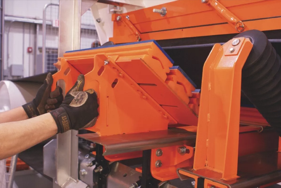
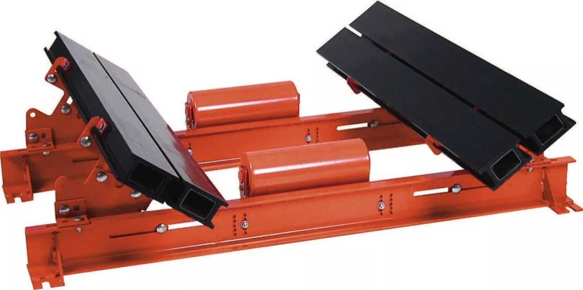
Following the impact cradle within the 10.3 m long (34 ft) settling zone, the team recommended a series of adjustable slider cradles that support the belt to prevent spillage from belt edge sag and to eliminate entrapment points where material commonly got caught. To avoid belt fraying and reduce drive-power consumption, the loaded belt glides over low-friction, 62 durometer (shore D) UHMW polyethylene sidebars featuring the company’s unique “box” design.
The sidebars are “double-life,” which means they can be flipped over when one side is worn, providing a second wear surface. Using only hand tools, a single worker simply removes the release pin and pulls the unit away from the frame on its track-mounted sub-assembly to adjust and replace components quickly.
The proposal included track-mounted idlers to be placed in the tight spaces between support cradles where material can get trapped or escape.
With slide-out/slide-in roller frames allowing idler service without the need to raise the belt or remove adjacent idlers, track-mounted idlers help stabilize the belt path between carriages to assure a tight seal through the entire chute box.
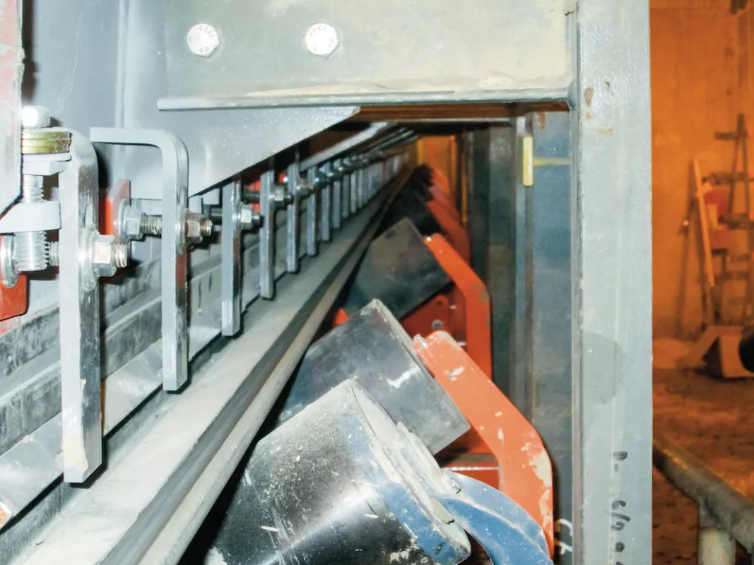
Another key element of the assessment was an external skirting system along the chute box, sealing the chute to the belt. Specially designed to provide dual-seal efficiency with a one-piece 70 Shore D EPDM durometer rubber composite skirt and an attached strip, the skirting floats on the belt and self-adjusts to maintain an effective seal.
Offering chemical resistance and low-abrasion index characteristics, once the skirt is worn on one side, it can be flipped for dual usage by disengaging the 182.9 cm (6 ft) long angle clamps. This can be done quickly using hand tools.
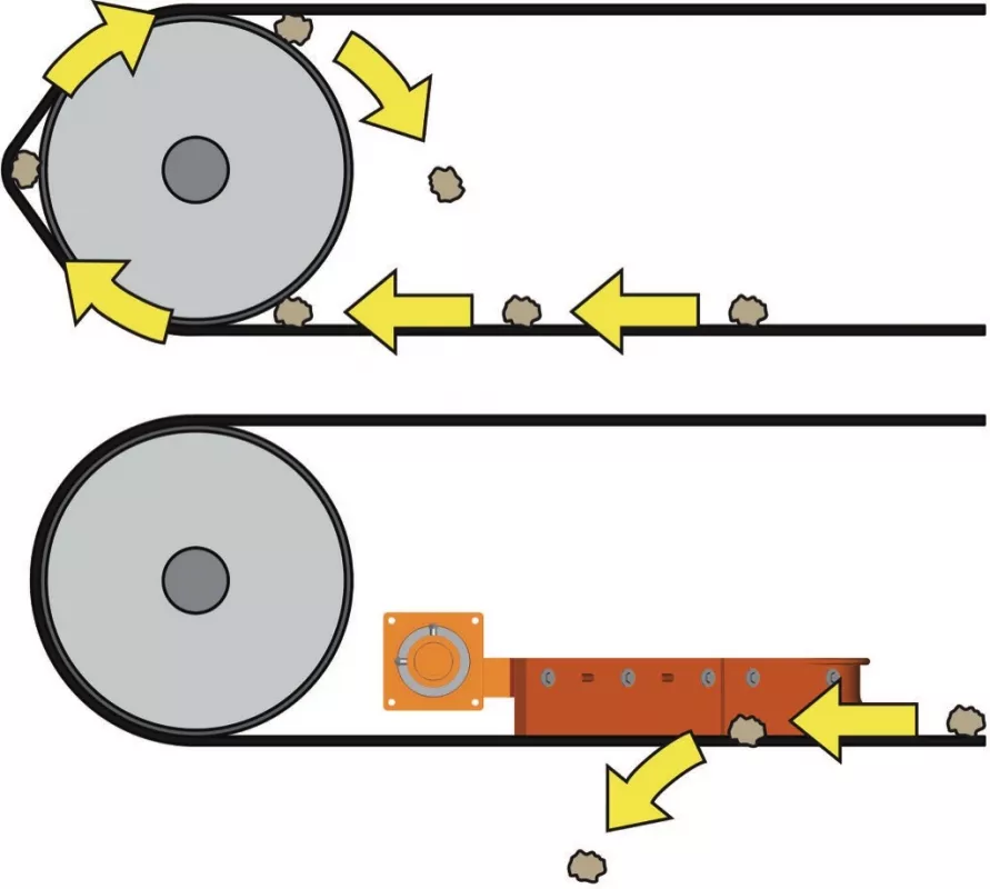
“The wandering belt issue was also a huge concern, so we recommended a series of belt trackers with a parallel steering and training system every fifty feet,” Cole added. “Another cause of misalignment was material getting caught between the belt and tail pulley, so we proposed a torsion V-plow as well.”
Mounted on a dual steel bar attached to the mainframe a few feet from the tail pulley, the V-plow has a unique suspension system that allows the polyurethane blade to rise and fall with fluctuations in belt tension. Any material carried back on the top of the belt return is deflected to either side of the frame before it reaches the tail pulley.
By reducing the impact of material with the rock box, improving the integrity of the settling zone and assuring the belt remained tracked throughout the process, the system is designed to mitigate spillage and improve the health of the entire conveyor.
Results
Installation by Martin Engineering technicians took less than two weeks, and coincided with scheduled breaks for other improvement projects addressing issues throughout the facility. According to Akula, the B-06 improvement was one of the most critical elements to the operation.
Since the conclusion of work in early 2014, there has been no unscheduled downtime of B-06. Moreover, monthly Walk the BeltTM inspections conducted by Martin Engineering technicians have recorded healthy pulleys and no significant belt damage or need for replacement. Cleanup time of spillage has been significantly reduced to an as-needed basis, without the requisite system shutdown.
“We are extremely impressed with how the system is performing,” Akula concluded. “The service and maintenance have been excellent, and we are already working with Martin on other projects to further improve operations.”
■

