
(From the archive of ”bulk solids handling", article published in Vol. 36 (2016) No. 1 , ©2016 bulk-online.com)Splitters have taken an important position within the pneumatic conveying systems and are applied in different designs. On the other hand there is not much literature dealing with the phenomenon “splitter”, and providing assistance regarding application possibilities, dimensioning, selection and experiences during operation. The available literature mostly deals with answers to specific questions, like for example pressure losses in various ramifications, etc.The present article intends to close this gap and to provide an overview over the possible applications and typical configurations of splitters, with their advantages and disadvantages. Furthermore various selection criteria for usage of splitters are introduced and discussed.In addition, dimensioning and operation of splitters are discussed. Possible susceptibilities to interferences are pointed out and measures to ensure or promote a smooth operation as well as operation experiences with splitter systems are introduced.
1. Splitters – Definition and Limitation for further Discussion
The term “splitter” stands for a multitude of process technologies in the bulk material industry. They all have in common that they are used to evenly distribute a material flow and to simultaneously lead it to several target locations. This can be done both within a mechanical conveyor section, e.g. with a special spreading auger and injectors (see Fig. 1), as well as through a constructive element (the splitter) in a pneumatic conveyor section. An alternating distribution is given if only one particular target location out of several other possible locations is to be reached (e.g. with the help of a pipe branching). In case all possible target locations are to be fed, we speak of an even distribution. This article deals with the even and simultaneous distribution of particles, in which a conveying gas (usually air) serves as a pneumatic carrier medium.
Splitters are mostly used in engineering plants, such as for the treatment of flue gas, where a sorbent is evenly blown into a flue gas channel in up to 16 different locations. A further application is dust firing in coal power plants, in which an even coating of the blown-in dust and air mixtures over the cross section of the boiler are an important precondition for an optimal and low-emission combustion.If no splitters are applied in these cases, a separate conveyor track is needed for each single air injection point, together with a conveyor- and dosing unit and possibly with air supply (see Fig 2a). Apart from the spacial problems, this leads to a multiplication of costs.An initial saving in costs can be achieved through a downstream splitter, with which the total amount of air is divided onto the individual conveyor tracks and metering points respectively. Hereby the distribution (of air) can be done as an equilibrium distribution (Fig. 2b) or through the application of device/venture nozzles as forced distribution (Fig. 2c).
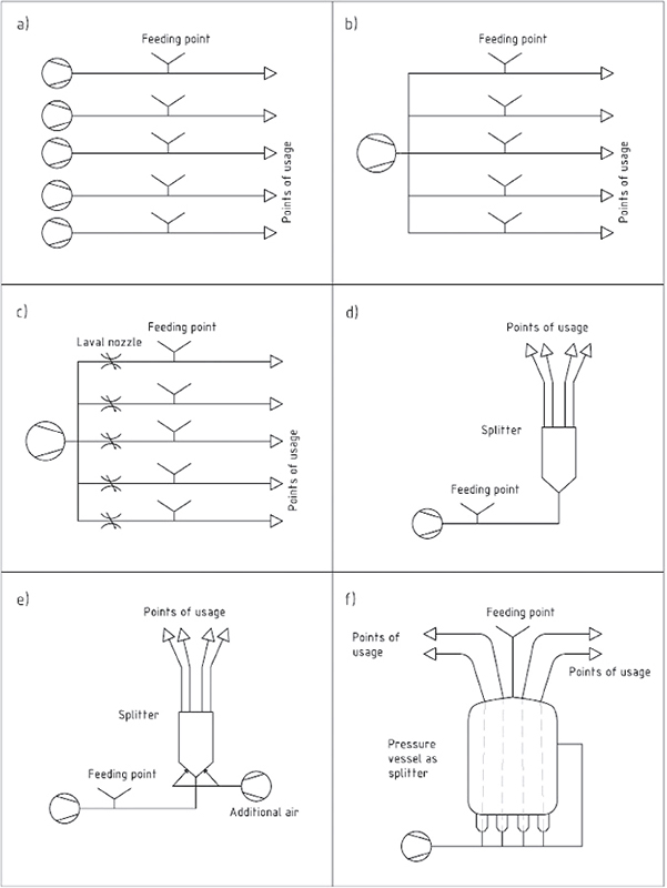
Significant savings can be achieved if the splitter is arranged delivery sided with an optimal arrangement close to the injection locations (Fig. 2d). In this case the air supply, dosage organ, conveying organ and a section of the conveying line are only single executed. While feeding against higher pressures or at dense phase conveying, the distribution could also be realized in the conveyor mechanism (Fig. 2f).The splitters discussed in this article are splitters for a distribution within a pneumatic conveying section as a distributing conveyor organ (e.g. in Figs. 2d/2e) or as a branching organ in the conveyor line (like for example in Fig. 2f).
1.1 Splitter Designs
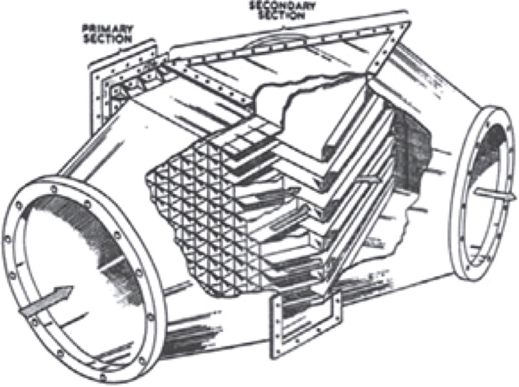
Based on material characteristics, conveying tasks and conveying types (dilute phase/dense phase) there are multiple designs of splitters. Not all of them are well thought through or suitable for each and every case. For example the distribution can be done from a fluidized bed, the splitter can be streamed through from up to down or vice versa, and there are also horizontal splitters. As an example, so-called riffle boxes, which are used for the distribution of coal dust to (mostly 4-6) burners in coal-fired power plants are well known (Fig. 3). Rotating splitters have also been and are still used for the distribution of a mass flow. However, the most used are the dilute phase stream splitters with various distribution mechanisms, which are streamed through from bottom to top.
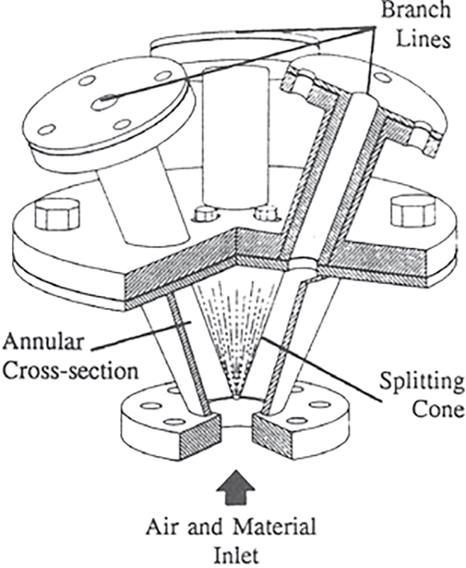 Fig. 4: Fuller Konus-splitter.
|
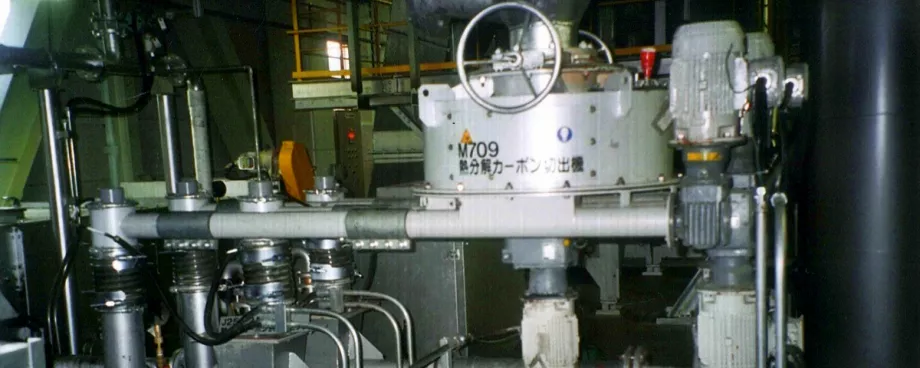
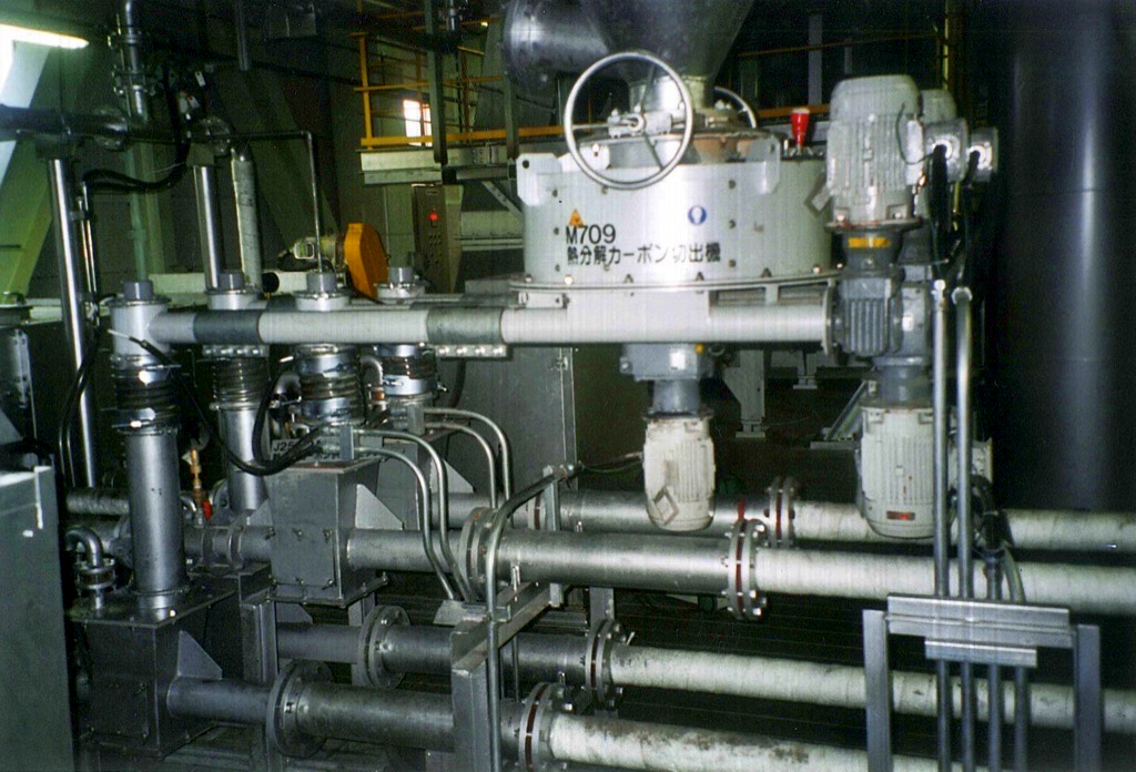
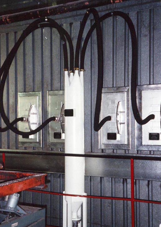 Fig. 5: Four-fold splitter for slaked lime in a power plant.
|
1.2 Mode of Operation of Dilute Phase Splitters for Powders
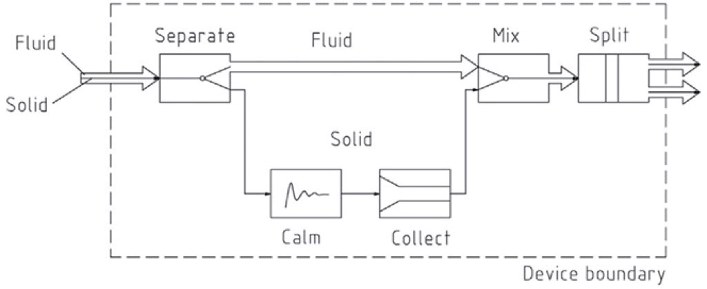
For dilute phase splitters and ramifications discussed in this article, Lempp [5] had already found out in 1966 that it is necessary to segregate the particles and the gas and to calm down the solids, before mixing and distributing them again. Fig. 6 shows the basic strategy in distributing gas-particle mixtures, with the example of a patent drawing (K.-H. Mohr, 1988, patent specification DE 3626983 C2).
In his examinations Lempp has shown that it is not a satisfying solution to use separate plates or open branches. For example, when entering the splitter with uneven distribution concentrations of the particles across the tube diameter (formation of strands) this uneven distribution can be observed behind the splitter as well. Only when using a standard T-type element, where the particles were slowed down to a complete halt after the perpendicular impact, a relatively even admixture and distribution of the solids was measured.This is the reason why so-called riffle box splitters work deficiently, despite a high number of sub sheets and subdivision of plots, if the particle distribution in the feed is uneven. This shows that there is a systematic fault.The splitter shown in Fig. 3 will also not work with adequate accuracy, since the occurring strands will preferably charge a single outlet.
1.3 Requirements for an “Ideal”Splitter
In order to limit the varieties of splitters and designs, only dilute phase splitters with a maximum load of up to 15 kg solids per kg of gas and a maximum grain size of one mm are discussed in the following section. The perfusion of the splitter is from bottom to top in perpendicular position. An ideal splitter has to fulfil the following requirements:
- Separation of gas and solid
- Levelling out and homogenization of the gas flow
- Strands should not penetrate the whole splitter body
- Proportioning of the homogenized gas-solid stream
Since a complete separation of solid and gas is difficult to achieve, a reduction of the gas velocity to the rate of descent of the solid particles is aimed at. In order to achieve this, the cross-section of the splitter is expanded accordingly. This expansion is continued up to a certain length, in order to dissolve strands and achieve an equalization of the mixture. Only after that, the separation of the mixture is done, according to the number of outlets.
1.4 Splitter Layout - FAQs
- Is there an optimum number of outlets?
The number of outlets is based on procedural requirements. In this type of splitter, up to 16 outlets have been realized in parallel. However mostly 4 to 6 fold splitters were realized, since in this case the individual lines are less likely to be obstructed, due to the occurring reset forces. In a dual distribution, for example, the gas velocity doubles due to congestion, thus significantly increasing the static pressure as restoring force on the plug. In a 16 fold splitter the velocity in the remaining 15 outlets only increases by barely 7%. In this case the restoring forces are correspondingly lower.
- How can the obstruction of individual outlets be detected?
The fastest and most reliable way to do this are pressure measurements before/after the splitter. The conveyor lines that are flown through normally have higher temperatures than the obstructed ones; therefore it is also possible to conduct temperature measurements after the splitters for detection of disturbances. Flow rate measurements in the conveyor lines behind the splitters, which are based on electronic procedures (electrostatic noise, microwaves) are also suitable. Based on the chosen comfort, these methods allow a qualitative statement on differences in flow rates.
- Which accuracy can be achieved with splitters?
In case the flow-rate error refers to the theoretical mean value for each branching line after the splitter (example: total flow of solids 1000 kg/h; 4-fold splitter; mean value 250 kg/h), and an inappropriate splitter type, insufficient strand dissolution, too many outlets, changing solid material characteristics or slant inflow, deviations of up to ± 35% can be seen. However, if the prerequisites are optimal, the distribution error can achieves less than 5%, and the range below 10% can usually be achieved. In the above mentioned example this means that the conveyed amounts per line lie at a minimum of approx. 235 kg/h and maximum of 265 kg/h. Lower accuracies often are sufficient, since the main attention is on the distribution of the total flow rate as such.
- Is it possible to inject additional air, and if yes, where?
Due to procedural reasons it is sometimes necessary to increase the amount of air behind the splitter, either to reduce the load (and thus the line pressure loss) or to better adapt of certain geometries of pipes. Due to the increase in turbulence, the additional air can then contribute to equalizing, however the splitter has to be designed correspondingly longer (higher).
- Can different quantitative distributions of the flow rate also be achieved?
This is possible within certain limits, for example two lines with a total of approx. 40% mass flow were impinged from a 4-fold splitter, the other two were impinged with a total of 60% mass flow. The outlets at the splitter and the pipe cross sections behind the splitter were adapted accordingly. The required distribution was achieved.
- Where should the splitter be positioned in the course of the line?
From the procedural point of view, a division is already possible after a few meters of conveyor line. In that case the conveyor lines (and the pressure losses) behind the splitter would be equal. The most economical solution, however, is a division as close to the injection points as possible, since in that case only one line needs to be directed to the splitter, and the remaining multiple lines can be very short. In the next chapter a few other hints are given for the equalization of the pressure loss and the division of the flow rate.
- How sensitive to wear is the introduced splitter?
Wear rather happens at locations, where local high gas velocity (and respectively solid material velocity) occurs. This means, the main wear areas in a splitter are the distribution header and/or the area of additional air injection. Therefore, with conveying goods that lead to high wear, the distribution header can be removed and exchanged, if needed. It might be possible to coat the inside with a wear protection. With the removable tip it is also possible to change the distribution.
1.5 Calculation of the Splitter
The main calculations for the splitter are, apart from the area division in functional dependence to the number of outlets, the sinking velocity, as well as the estimation of the additional pressure loss.
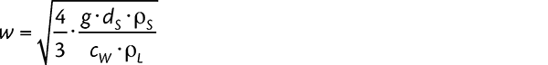
1.6 Calculation of the Sedimentation Velocity of Individual Particles
The sedimentation velocity of the individual particles w is calculated from the equilibrium of the weight force FG (perpendicular down) and the circulation force of the surge flow FW (perpendicular), neglecting the lift forces as follows:
 |
 |
where:
| As | = | Projected area of the particle | [m2] |
| g | = | gravitational acceleration | [m/s2] |
| dS | = | cross section of particle | [m] |
| ρS | = | particle density | [kg/m3] |
| cW | = | drag coefficient of particle | [-] |
It should be noted that this equation only applies to individual particles; the sedimentation velocity of particle collectives is different, depending on its composition.Usual sedimentation velocities of fine particles are in the range of 0,5 to 2,5 m/s. These values apply to an individual particle. Practical values can be determined through experimental determination of the sedimentation velocity, e.g. in the Gonell-classifier.
1.7 Calculation of the Pressure Loss in the Splitter
The pressure loss in the described splitter is mainly due to the re-acceleration of the solid particle/gas mixture. It is fairly accurately described in the following equation:
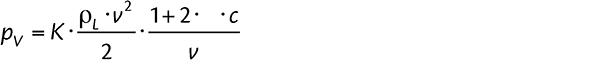 |
 where:
| Δpv | = | Pressure loss in splitter | [Pa] |
| K | = | Empiric factor (value ≈1,2) | [-] |
| ρL | = | Gas density | [kg/m3] |
| v | = | Gas velocity | [m/s] |
| μ | = | Load (kg solid per kg gas) | [-] |
| c | = | Solid particle velocity | [m/s] |
At usual velocities, system pressures, temperatures and loads, the additional pressure loss of such a splitter generally varies in the range of 8 up to approx. 50 mbar.
2. Operation of the Plant
In order to achieve the most possible even division of the mass flow, some further points need to be taken into consideration while setting up the splitter (see Fig. 7):
- The splitter has to be set up perpendicularly.
- Before entering the splitter, the perpendicular incident flow length must be at least 15 (20 is more favourable) times dE (whereby dE is the inner pipe diameter at splitter inlet).
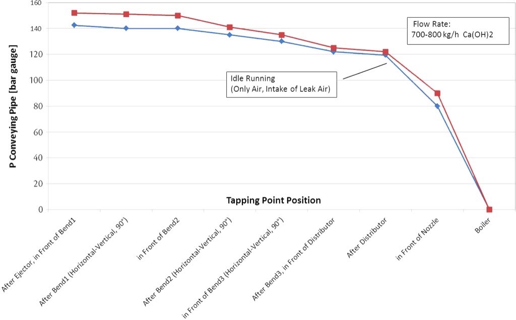
An even division of the bulk mass flow rate can only be assured, if these minimum prerequisites are observed. It is recommended that a corresponding straight wake (10 to 15 times dA, dA = inner pipe diameter at splitter outlet) is also observed.A disturbance-free operation of the conveying is of particular interest. The aim is to achieve accuracies in the range of ± 5 to 10%.The splitter is one part of a general plant, and in setting it up, fluidic aspects have to be observed, in addition to geometrical sizes.It is important that the specific pressure loss occurs at the end of the conveying line, so that small differences in the lengths of feed pipes after the splitter can be neglected compared to this pressure loss.This can easiest be done by attaching a nozzle with a defined pressure loss to the end of the conveying pipe. A respective example is depicted in the diagram (Fig. 8). Further explanations are provided in the following chapter.
The splitter lengths are dependent upon material characteristics, an additional air injection and the number of exits to be supplied. Usually, these lengths are in the range of 5 to 10 times the diameter of the splitter.
3. Homogenization of the Throughput
Fluid mechanic correlation at the splitter can be well described through a simplified electric circuit. The following is valid as an analogue:
- Voltage U ~ Pressure gradient
- Current I ~ Material throughput
- Resistance R~ Resistance behaviour of pipe
The aim is always an evenly distributed throughput of material. Nevertheless, it often happens that due to local circumstances, the conduit after the splitter cannot necessarily be implemented absolutely even. This leads to the fact that both the resistances R1 to R4 and the throughput turn out differently, as they are directly linked with the pipe resistance (see Fig. 9).
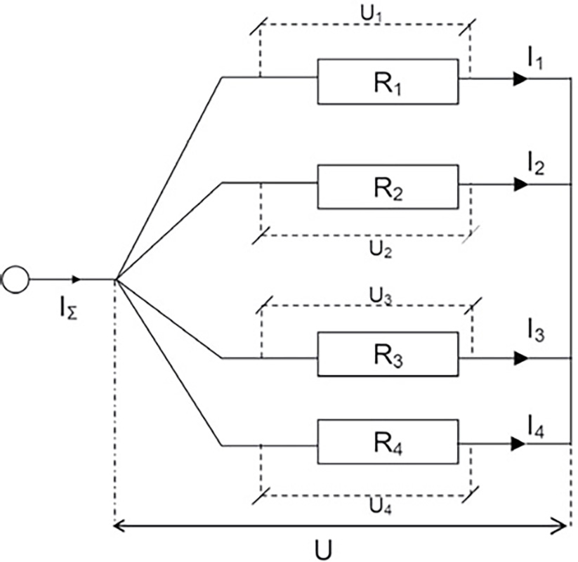
In this arrangement the following applies:
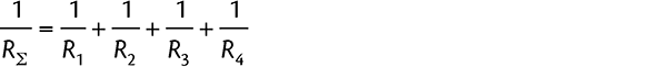 |
Changes in resistance have a direct effect on the changes of throughput (of current). However, in most cases this effect is not desired. A small “trick” to avoid this is to connect an additional resistance in series (see Fig. 10).
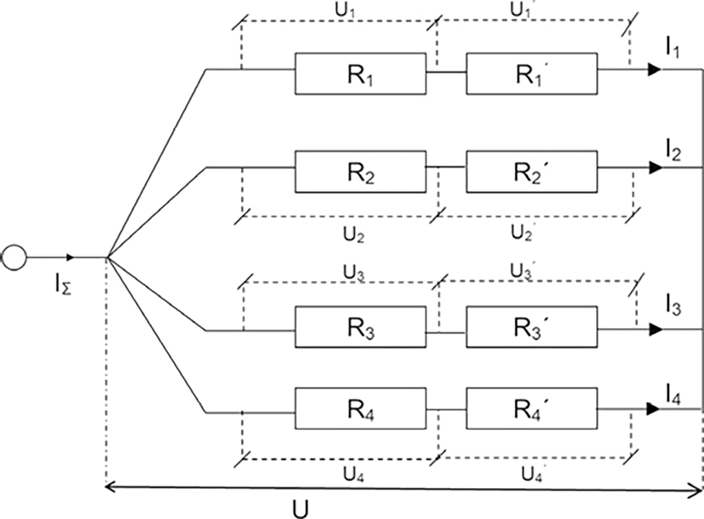
In case the additional resistance is chosen big enough, differences in pipe resistance can be neglected. It is obvious, however, that the voltage has to be increased to keep the throughput.Here the following applies:
 |
Hereby the additional resistance (e.g. in the form of an outlet nozzle at the end of a pipe) determines the uniform distribution of the solid material in the splitter. However, it should be noted that the uniform distribution in other types of splitters can only be done if all strands are dissolved there.
4. Examples of Operating Plants
Examples of executed plants are dense phase splitters for pulverized coal out of a pressure vessel and a dilute phase splitter in the co-firing of animal meal. Both are applications from the power plant sector, but can similarly be found in the chemical industry.
4.1 Dense Phase Splitter from a Pressure Vessel
Fig. 11 shows the arrangement of a plant which supplies 2 x 6 pulverized coal burners in dense phase mode with a loading factor of 20 to 35 kg solids per kg air. The performance per string lies at approximately 1 200 kg of coal per hour. The inner diameter of the individual conveying lines is 35 mm. These pipe strands can be switched on and off individually.
4.2 Dilute Phase Splitters for the Conveyance of Animal Meal
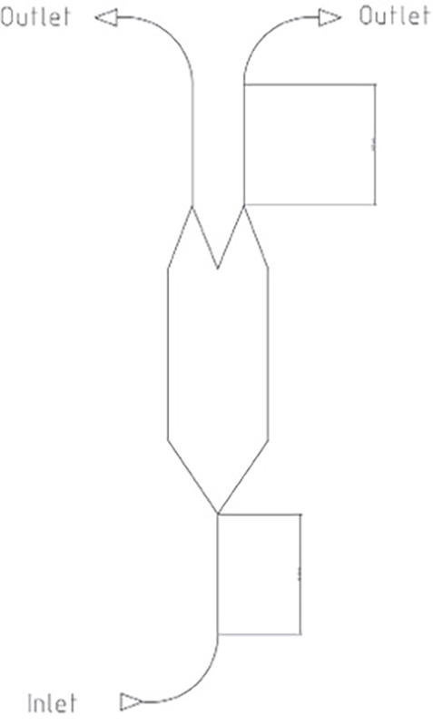
The plant shown in Figs. 12 (layout) and 13 (detail photo) directly conveys meat- and blood-meal from the silo-truck to the boiler.
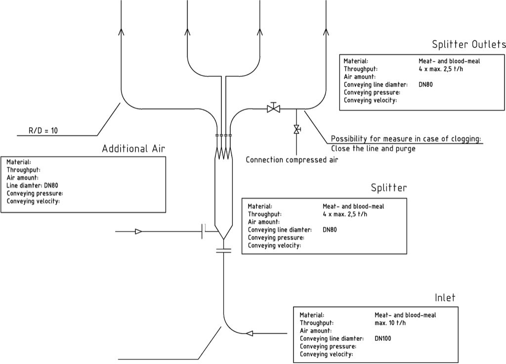
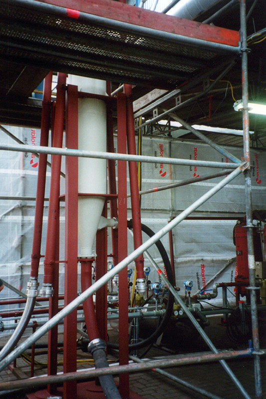
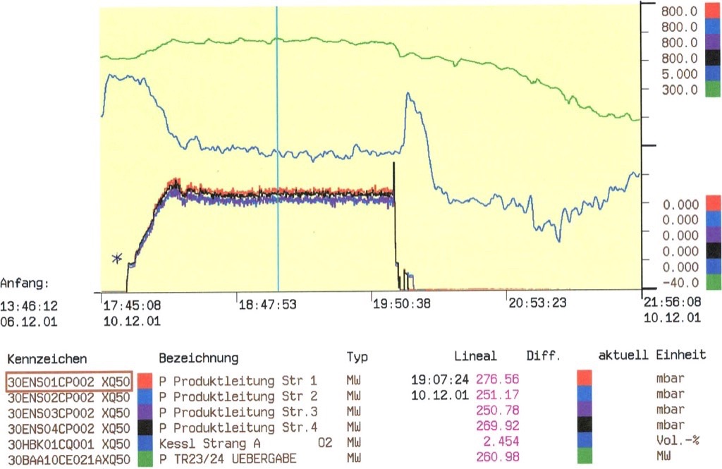
The material can be conveyed relatively easily, which is partly also due to the relatively even particle from. In order to keep the required velocities in the burner pipes, a considerable amount of additional air was injected into the lower area of the splitter. The injection is done tangentially (by now it is done from both sides to avoid a tilted position), in the lower part of the splitter.Fig. 12 clarifies the arrangement of the plant. The air is lead twice to the truck (cover and propellant air) and once to the fourfold splitter (additional air). The amount of air is divided in such a way, that the desired output of 4 x 2,5 t/h is achieved. The pressure in the truck is deliberately kept low, so that the desired performance is achieved.Unfortunately the picture only shows the lower part of the splitter. In addition to the pipelines leaving the splitter four more single pipes, which are served from so-called interchangeable silos, can be seen.As can be seen in Fig. 14, the distribution of the material is very even and the conveyance is relatively quiet. The O2 content, which is also shown, and the boiler load show a good burning and increase of load.
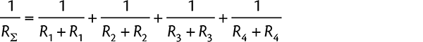
A silo dosage station can be coupled to each pipe if needed, so that there is no exclusive dependence on the silo-truck. The silos are also transportable. The big advantage of this solution is the clean handling without interferences through pollution, etc. Experiences during operation have been markedly positive after the start of the operation.A third example, presented in Figs. 15 to 17, shows a pneumatic supply system for injecting a flyash-lime mixture into a reactor.
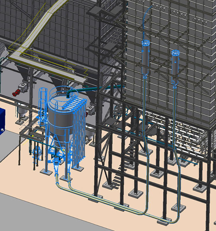 Fig. 15: Pneumatic injection system with two eightfold splitters for supplying a reactor with a flyash-lime mix.
|
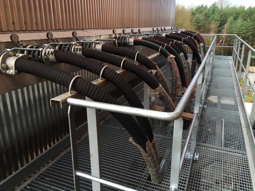 Fig. 16: Sixteen Injectors supplied by two 8-fold pneumatic conveying lines.
|
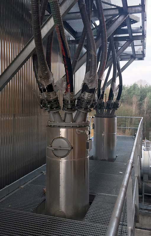 Fig. 17: Two splitters, supplying eight pneumatic injection lines each.
|
|
The purpose is to supply the reactor with 23 tons per hour of the aforementioned mixture with a volume flow of air of 2000 m3 per hour. The material is stored in a single silo.The challenge was to distribute evenly distribute this mass flow onto 16 injectors at the reactor. For this purpose the silo was designed with a twin outlet, which supply two eightfold splitters which in turn supply the injectors.The plant was installed and brought into operation in August 2015 and has worked to the satisfaction of the operator since then.
5. Conclusion
Splitters in pneumatic conveying plants require a careful design and calculation. Not all splitter types are ideal for each and every application.Specific characteristics, dependent on geometry and material, were depicted in the example of a dilute phase splitter for fine grain bulk material. Frequently asked questions were responded to. Furthermore the general calculation and layout, including operation behaviour and integration into the plant environment was discussed.Examples of established splitters were introduced and the specific case of application was explained. Respective literature and patent citations are listed in the following.
References:
- Morimoto, T., A. Yamamoto, and T. Nakoo: On the Behaviour of Air-Solids Mixture in a Pipeline for Pneumatic Conveyance with Single or Double T-Branches. Bull. J.S.M.E., Vol. 20 (1977), pp. 600–606A
- Selves, T.P., and R.N. Bames: Review of in-line splitting techniques used in pneumatic conveying; Trans. Inst. Eng. Aust. Mech. Eng. VME 18 (1993) No. 1, March, pp 51–56
- Low, H.T., S. Kar, and S.H. Winoto: Pneumotransport of Solid Particles through Manifold System; Proc. Third Asian Congress on Fluid Mechanics, Tokyo, (1986) pp. 630–639
- Morikawa, Y. et al.: Pressure drop and solids distribution of air-solids mixture in horizontal unsymmetrical bends; Journal of Multiphase Flow, Vol. 4 (1978), pp 397–404
- Lempp, M.: Die Stroemungsverhaeltnisse von Gas-Feststoff-Gemischen in Verzweigungen pneumatischer Foerderanlagen; AT Aufbereitungstechnik 7 (1966), pp. 81–91
- Thomas, G.: Verteilungsmessungen an einem 16-fach Staubverteiler; LCS-Steinmueller, 1986
- Patent OS DE 28 29 867; Ruhrkohle AG, Inventors: Schroer, Schedbauer, Zillessen
- Patent OS DE 28 32 846; Rockwell International Corp; Inventors: Oberg et al.
■

