
It is well known that excessive misalignment of roller bearings, such as those installed in conveyor idlers, leads to a reduction in the bearing life. The excessive misalignment in the conveyor idler bearing context is a result of the cumulative effect of acceptable manufacturing tolerances and assembly, together with the load that the idler must carry. However, the reduction in life and the determination of estimations in order to quantify the reduction is currently unknown, or at least withheld from general application.
According to Mike Stewart-Lord [1], ‘Idler roll bearings should be able to accommodate a misalignment of up to 0.004 radians. This takes into account shaft deflection under load and manufacturing inaccuracies which cannot be avoided. The figure of 0.004 radians is reasonable because misalignment above this value can have an adverse effect on many seal designs. Spherical roller bearings are unacceptable for idler roll applications because of the large cost disadvantage. Self-aligning ball bearings are not suitable since the axial load, especially in the wing rolls, is too high for satisfactory operation.’
It is noted that 0.004 radians is very nearly 0°-14’ and is the recommended maximum deflection for 420205 bearings, which were basically the most common idler roll bearing in South Africa at the time.
So it appears that very little has changed with respect to the effects of excessive deflection on the life of the idler bearings.
Excessive misalignment can be found in the actual manufacture of the idler rolls, where the bearing housing and end disc pressing is not properly inserted into the roll tubing. It is for this reason that a misalignment tolerance is proposed, and most of the major users and mining houses in South Africa specify a manufacturing tolerance. A conservative allowance would be 0°-6’ (0.001745 radians). It is very difficult to actually measure this misalignment, so it is essentially a theoretical reduction in the bearing misalignment allowance as specified by the bearing manufacturer.
Of course, the major source of misalignment should be the actual loading of the idler roll as a result of the material being carried. However, there have been instances where even return idlers (which are intended to carry the belt mass only) have shown a serious reduction in operating life. This can only be ascribed to poor manufacture and a lack of maintenance of the assembly machines in the manufacturing process, which may require third party quality checks.
1. The Load on the Roll
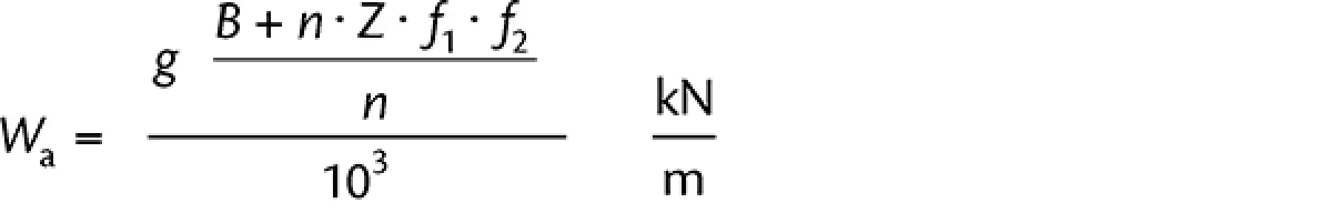
The load that is applied to the most heavily loaded roll in an idler set may be determined from the equation
|
(1) |
where:
| Wa | = | actual load carried by the most heavily loaded roll [kN/m] |
| g | = | gravitation constant, 9.81 m/s² |
| B | = | mass of the belting [kg/m] |
| n | = | number of rolls in the idler set |
| Z | = | material load [kg/m] |
| f1 | = | dynamic load factor |
| f2 | = | burden factor |
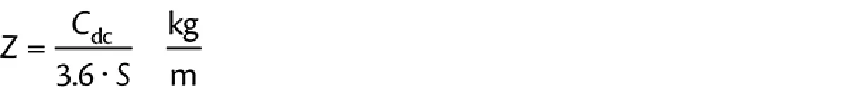
The material linear loading is found by
|
(2) |
where
| Cdc | = | design capacity |
| S | = | belt speed |
The dynamic load factor is found from

|
(3) |
The value of Cx may be determined from Table 1.
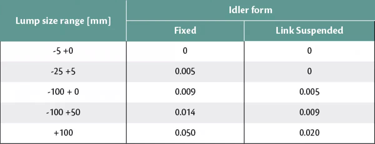
In the majority of cases, it is perhaps wise to use only the factor for +100 mm material, since idlers carried in the plant stores will have to be available throughout the plant, based on the belt width and not the material lump size.
The burden factor f2 is found from Table 2. The values refer to a belt loaded to 100 %. It must be appreciated that the burden factor will increase with decreasing belt loading. Typically, as the belt loading approaches about 10 %, the burden factor will be approaching 1.
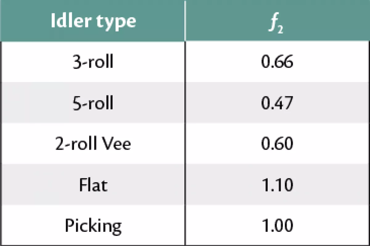
Tables 1 and 2 and the following equations are extracted from the CMA Diploma notes [3].
An estimate of the burden factor related to the belt loading may be made from the following empirical equations.
For 3-roll idlers,
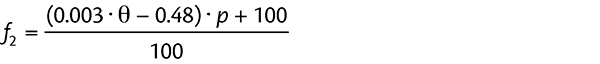 |
(4) |
For 5-roll idlers,
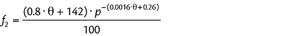 |
(5) |
where
| θ | = | wing roll angle degrees | |
| p | = | percentage loading |
It is noted that the value of f2 for flat and 2-roll Vee form idlers is as shown in Table 2 and is applicable for all percentage loadings.
It can be shown that the allowable load for deflection is determined by
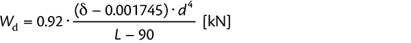 |
(6) |
where
| δ | = | the allowable deflection limit for the type of bearing radians | |
| L | = | The gauge length of the roll in question (see SANS 1313/1) |
The deflection-based idler pitch is then given by
 |
(7) |
Since the deflection-based idler pitch is determined by Eq. (7) shown above, it follows that the actual deflecting load
| (8) |
and this load is applied to the roll assembly.
Manipulating Eq. (6), the actual slope of deflection may be determined as
 |
(9) |
where d refers to the idler roll shaft diameter (given as the idler series).
The maximum allowable slope of deflection is given in the standard for each type of bearing. For example, for seize resistant cage bearings, δallowable = 0.00407 radians, while for deep groove ball bearings with C4 clearance, δallowable = 0.00436 radians. It is noted that these values are reasonably conservative and are applied before any reduction for manufacturing tolerances.
For the analysis, the active slope of deflection
| (10) |
Applying this to Eq. (6), the component of the load which causes the excessive deflection may be determined as
 |
(11) |
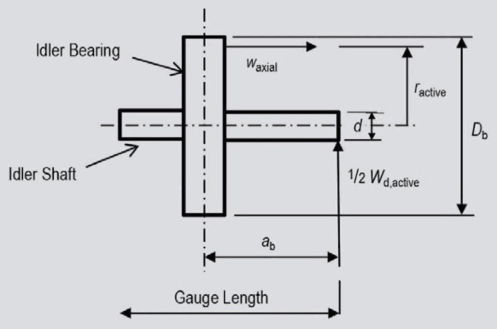
The excess deflection results in an axial force, when the balls are forced into the inner and outer races of the bearing.
The active radius of the contact between the race and balls may be estimated from
| (12) |
rounded up to the nearest whole number. In this case, the parameter Db refers to the bearing outer race diameter.
Some values of the diameter of the bearing (Db), the bearing width (wb), the dynamic load rating (C) and a recommended deflection (δ) may be summarised as shown in Table 3. Note that the maximum allowable deflection is based on C4 clearance deep groove bearings, set at 0°-15’. The maximum allowable deflection through the 420 series bearings is set at 0°-14’.
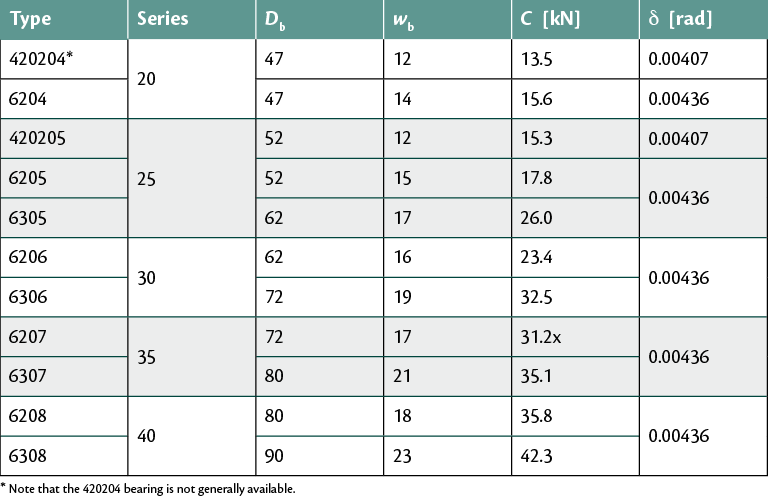
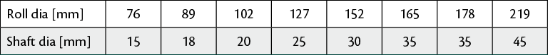
With reference to Fig. 1, the lever arm ab, is estimated at ab = (2 · d) + 5 mm, where d refers to the idler series or roll shaft diameter. The value of ab may be accepted as 45 mm, being a weighted average value, as applied in Eq. (4).
The axial force
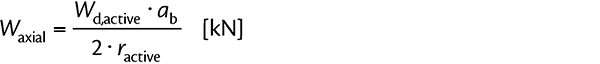 |
(13) |
The equivalent dynamic bearing load may be determined as
| (14) |
where the subscripts r and a refer to the radial and axial loads respectively.
It is clear that Fr = 0.5 · s1 · Wa, where Wa is determined in Eq. (1).
The axial load is accepted as Fa = Waxial as determined in Eq. (13).
The values for X and Y may be accepted as X = 0.44 and Y = 1.5 respectively, for the worst case condition. The values of X and Y are taken from Table 4 in the SKF general catalogue 5000E.
Using the life equation from the CMA Diploma notes Chapter 5
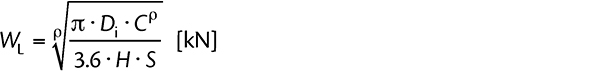 |
(15) |
for each bearing, where
| Di | = | idler roll diameter | mm |
| H | = | live time | h |
| S | = | belt speed | m/s |
| C | = | bearing load rating | kN |
| r | = | 3 for ball bearings |
Substituting WL = Pequiv (from Eq. (15) above) and manipulating the equation, the bearing life may be estimated as
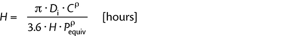 |
(16) |

