
1.1 Example
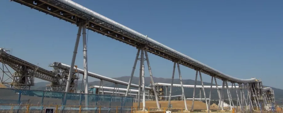
An overland conveyor 1200 mm wide, running in 3-roll 35° Ø127 series 25 carrying idlers fitted with deep groove ball bearings (6205), at a belt speed of 3.8 m/s handles 2000 t/h and the belt mass is given as 28.1 kg/m. The idlers are pitched at 2.25 m.
The lump size is specified at 150 mm, which results in f1 = 1.722, f2 = 0.66, and Z = 146.199 kg/m.
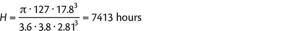
C = 17.8 kN as obtained from catalogues; ρ = 3. Standard endurance life H = 40 000 hours. The roll gauge length is 460 mm.
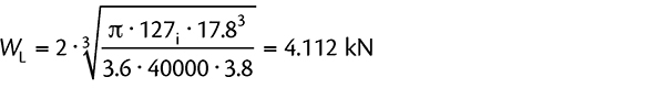
Thus, from Eq. (1)
 |
For
 |
the ideal pitch for endurance would have to be less than
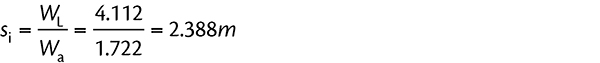 |
and the selected idler pitch of 2.25 m is ideal from the endurance aspect.
Eq. (6) gives
and, from Eq. (7)
 |
which is beyond the limit of 0.00436 radians for the specified bearings. Using Eq. (8), the active slope of deflection is determined as
Applying this to Eq. (9), the deflection component
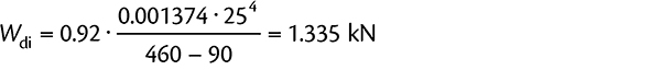 |
From Eq. (8), the active radius is estimated as
For the value of ab = 45 mm, the axial force is
 |
Applying Eq. (11), with X = 0.44 and Y = 1.5 for bearings with C4 clearance for
 |
results in
Substituting this into Eq. (13) gives
 |
which is clearly unacceptable, when considering a required design life of 40 000 hours.
1.2 Increased Bearing Specification
Applying a 6305 bearing, with C = 26.0 kN, Db = 62 mm and δ = 0.00436 radians, the value of WL would become 4.680 kN and the endurance based pitch 2.717 m which is acceptable.
The actual deflection remains as before, at δactual = 0.005734 radians, just like the active slope of deflection δactive remains at 0.001374 radians and the deflection component at Wdi = 1.335 kN.
With the larger bearing, the active radius is estimated as
so that a value of 27 mm is used during further examination. The outcome of this is an axial force of
 |
and the equivalent dynamic bearing load
Since the value of C for the 6305 bearing is increased to a value of 26.0 kN, the life is then found to be
 |
which is marginal.
This solution has its own associated dangers, though. By far the majority of series 25 idler rolls in South Africa are made with either 420205 seize resistant cage bearings or 6205 TN9 C4 deep groove ball bearings. It is interesting to note that the clearance for the 420205 bearing is somewhere between C3 and C4 and could easily be described as C3½. It is also interesting to note that the 62 and 63 series bearings have a higher dynamic load rating than the conventional 420205 bearing.
Therefore, to specify a particular batch of idler rolls to suit a specific application (as in the example above) could easily lead to the incorrect specification of bearings being used for spares, with the premature failure of the rolls as a consequence. Idler rolls are sealed units and are not normally able to be disassembled without destroying them. The specification of the bearings inside the idler is therefore not easily seen and most certainly not visible without destroying the roll altogether. To try to identify with paint colours or stripes is also not very useful, because colours and stripes and so on can be easily painted over.
For this reason, to simply specify a heavier duty bearing in a consumable like an idler roll could lead to more maintenance problems during plant operation than they were intended to solve during the design phase. The result could therefore be much higher cost implications than any apparent savings that could have been made in the design stage.
2. Other Solutions
One of the most obvious solutions when faced with the excessive deflection of the idler bearings would be one of the following:
- Option 1: The idler pitch could be reduced so that the linear load is reduced accordingly
- Option 2: The idlers could be re-specified, with larger shafts
- Option 3: The idlers could be designed with stepped shafts.
Discussing these, Option 1 would immediately create a capex increase and may be unacceptable from the project costing aspect. Not only would a greater number of idler sets be required over the distance of the conveyor, but the conveyor structures (gantries and stringer modules) would have to be designed accordingly. In addition, the extra idler rolls would contribute to the annual mortality and therefore add to the system opex as well. Additional idlers as a result of a reduced pitch would also result in additional system tensions and power.
Option 2 is probably the simplest approach. However, the remarks with regard to additional capex would definitely apply. In addition, the larger rolls and shafts may impact on the standardisation of spares on the plant and could therefore become a bit of a stinging nettle.
It is also not good practice to oversize the shaft with respect to the idler shell diameter. A useful relationship is to consider the ideal shaft diameter to be about 20% of the shell diameter. On this basis, the ideal shell and shaft relationships may be tabulated according to Table 4.
If the shaft diameter (bearing series) is oversized, the rolling resistance of the roll increases and a greater load is required in order to rotate the idler roll satisfactorily. Thus, the Ø89 series 25 rolls would require a considerable load in order to rotate freely under load.
Option 3 is an one that has been mooted on several occasions in the past. There are some serious objections to stepped shafts, though, despite the attractive deflection benefits. Once again, idler rolls are sealed units and are not generally able to be disassembled without destroying them. The operating personnel would therefore be unable to easily see that the idler rolls have stepped shafts. In the case of an idler mortality, the staff would simply measure the ends of the shafts and order corresponding idler rolls, in good faith.
Of course, these rolls would very rapidly fail and the idler supplier will be rather unfairly blamed. To obviate that, a well-disciplined management system would have to be introduced and spares holdings would have to be carefully determined.
2.1 Stepped Shafts
The basic deflection at the bearings of a stepped shaft can be expressed as follows:
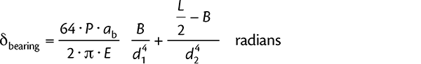 |
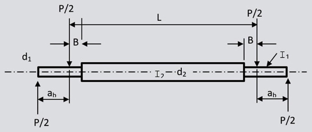
In this case, P refers to the load on the roll and
from Eq. (6). The parameter L is determined by subtracting twice the lever arm ab from the gauge length (see Fig. 2).
2.2 Example
We assume a 25/30 shaft, with the centre portion Ø30 mm and use the width of the 6205 bearing 15 mm, B = 7.5 mm, with
ab = 45 mm
Using the earlier example, P = 3875 N,
 |
and the effect of the stepped shaft is quite dramatic.
3. Identifying stepped Shafts
A possible standard method for identifying the presence (or otherwise) of a stepped shaft in an idler roll is presented thus:
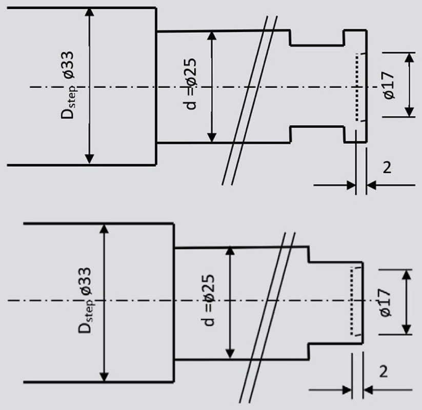
Perhaps consideration of an additional machining on the idler roll shaft end should be considered. One idea could be to counter-bore the shaft end for a distance of (say) 2 mm, to an inside diameter specified as the difference between the series (d) and the step (D), as per the sketch in Fig. 3. That is
Since the counter-bore will be under the closed end, there should not be a problem regarding the strength of the shaft in that area.
For the open end shafts, the counter bore will also be away from the actual bearing surface (at least, it should be) and the closest approach (for both open end and closed end) should be a minimum of 1.5 mm. This is again not too significant, because the closest approach is against the broached flat and that is not a shaft bearing surface.
However, it might become unworkable if the step is very large (say 40/25) and apart from such large steps being pointless, it may prompt a review of the idler specifications for that particular project.
This might be advantageous, because it may lead to limits on the practical stepped shaft. Nevertheless, in such a case, the counter-bore would reduce drastically.
Using the example of a 40/25 stepped shaft, the counter-bore would be reduced to
The small counter-bore may then easily be overlooked by untrained personnel.
he basis of the stepped shaft for idlers is that the larger diameter should not be greater than the upper diameter of the inner ring of the bearing. This would be required in order to allow the maximum shaft diameter without interfering with the cage or rolling elements of the bearing.
Table 5 indicates a range of shafts not necessarily in accordance with SANS 1313/1 [5], but which would accommodate most idler requirements.
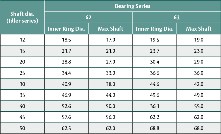
The maximum shaft step, based on avoiding interference with the bearing inner ring could therefore be written a
- for 62 series bearings: D = 1.18 · d + 3
- for 63 series bearings: D = 1.30 · d + 3
Of course, the tolerance of the counter-bore needs to be very loose and ISO H11 would be adequate. With this feature, when a roll needs to be replaced, the buyer will (should?) know that roll shafts with a counter-bore have stepped shafts and he/she can order accordingly, without the danger of accelerated mortality (of the rolls, of course) and the idler supplier unfairly getting a bad name.
Therefore, knowing the counter-bore diameter and the basic shaft series (bearing diameter), the stepped section can easily be found from
By creating a simple table, the buyers and operating staff can easily identify the shaft configuration for their particular plant and equipment.
To identify the step,
as expected, and the idler series would be specified as 25/33 in this case.
This basic exercise has highlighted that SANS 1313/1 does not seem to make allowance for open end shafts, other than to mention them (almost in passing) in Paragraph 3.15, Fig. 7.
Even then, the dimension N (SANS 1313/1 - Table 2, columns 6 and 7) is the same for both open end and closed end shafts. The author personally would prefer to use closed end shafts (coming from the Anglo American stable), but open end rolls are sometimes easier to fit for in-line idlers, which should be specified at transitions and convex curves.
An alternative identification method may be to hard-stamp the shaft ends. However, there is already provision for dating the assembly of the roll by stamping the shaft ends and this area could very easily become cluttered. In any event, many operations are quite liberal with paint and any markings on the shaft ends could easily become illegible.
■
