

Many power generation and industrial processes rely on storing coal in large bunkers. Over time changes in the type and quality of coal can lead to poor flow during discharge, causing processing delays and significantly reducing the bunker’s storage capacity. Manual intervention is frequently used to promote flow; however, this is a hazardous process for operators, and fails to provide a long-term solution to the problem.
An innovative technique developed by solids handling equipment specialist, Ajax Equipment, uses a multiple stage insert system to overcome bunker flow problems, creating a more favourable approach to existing outlets and spreading the flow to previously ‘dead’ storage areas of the bunker. The insert system has been used at Tata Steel Europe (formerly Corus Long Products) – a manufacturer of steel products at its plant in Scunthorpe, UK, to overcome coal bunker flow problems.
Coal Handling at Tata Steel
In the ironmaking process, molten iron is produced in a blast furnace using agglomerated iron ore, limestone and coke. The coke is produced in large coke ovens from coal with special properties. Coal is crushed and blended on the Scunthorpe site and transported to Appleby Coke Ovens via a series of belt conveyors. It is then stored in a large concrete service bunker which is sited above, and in the centre of the oven batteries.

The concrete service bunker (Fig. 1) was built in 1937 and is divided into two rectangular sections, one section holding 3000 tonnes of coal and the other holding 1000 tonnes of coal. It is about 17.5 metres tall and the 1000 tonnes section is 8 metres × 13 metres, whilst the 3000-tonne section is 20 metres × 13 metres. Coal is fed into the top of the bunker where it is distributed to one of the two sections and stored ready for discharge under gravity. Coal is discharged via a number of rows of outlets at the base of the bunkers into the charge cars.
In 1968 half of the outlets were blanked off and lightweight concrete was used to build up a steeper approach to the remaining outlets with smooth glass tiles laid on top to encourage flow. The outlets are arranged in five rows of four outlets on the 3000-tonne side and two rows of four outlets on the 1000-tonne section. Each row of four outlets operates together to fill a charge car which feeds the oven. Each outlet has a 640-millimetre diameter steel throat cast into the concrete. Slide gates are fitted to each outlet and the charge cars are filled with 17.5 tonnes of coal in, hopefully, one minute.
The bunker was originally designed to store local Lincolnshire and Yorkshire coal, but today it holds blended imported coal from around the world. A typical blend may consist of 60 percent Australian Coal and 40 percent North American. It is the particularly cohesive properties of the imported coal that has exacerbated the bunker’s flow problems, making the material more difficult to handle.
Poor Bunker Flow
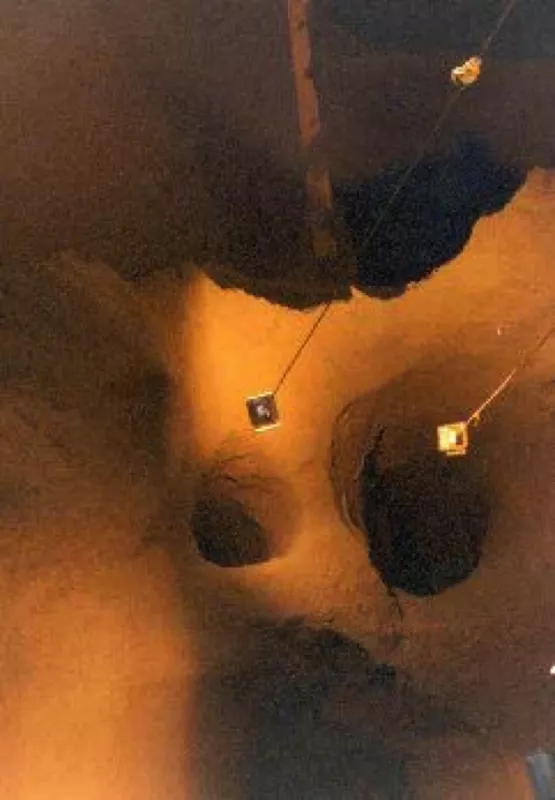
Although the huge bunker has a potential capacity of 4000 tonnes, the true useable capacity of the 3000-tonne section was nearer to 1500 tonnes. This was due to the phenomenon of ‘rat holing’ (Fig. 2) where a significant quantity of the contents was effectively trapped around the periphery of the bunker with only the central core of coal directly above the outlets flowing from the bunker into the charge cars. This meant that only a modest portion of the silo’s contents was retrievable – that which can flow through the 640-millimetre diameter outlet via a flow channel that flares to approximately 1 metre diameter over a depth of up to 10 metres. The bunker geometry and construction caused the residue to remain even when the central flowing channel is emptied (ratholing). Occasionally the narrow flow channel itself would arch, preventing flow completely.
Manual poking to stimulate flow exposed the operators to hazards and unhealthy working conditions associated with the collapse of arches and rathole walls. It involved the manual intervention, using a long scraper at the outlet, to promote coal flow – it can be quite a physical task. Poking for coal accounted for 16 percent of Appleby Coke Oven injuries in 2004. A number of other issues became apparent including under filling of ovens and adverse affects on the charging schedule.
In addition, severe constraints were imposed upon the filling procedure and operational flexibility by the limited usable inventory of the hoppers. The delays in the filling of charge cars and erratic calls for operator involvement were not efficient for operating cost or production.
The overall effect was to adversely affect production reliability and planning, and health and safety and operating costs issues. To overcome the rat holing effect, Ajax Equipment carried out a detailed review of the bunker design along with flow property tests and practical trials.
Diagnosing Flow Problems
The flow test results indicated the scale of the challenge to deliver reliable flow through the 640-millimetre outlets of the bunker. In general, flow regimes in hoppers show that mass flow – where all the bulk material moves to the outlet – gives the best flow potential for squeezing through the limited outlet sizes in the bunker.
Moreover, slip at the bunker walls (mass flow) and the ability to flow through smaller outlets can be best achieved with the right geometrical approach towards the outlet – planar rather than over axisymmetric flow. In addition, strength developed by a bulk solid during storage is dependent on consolidating stresses; if these can be limited then the bulk solid can be made to flow more easily as it is in a weaker condition. The solution devised by Ajax, combining these requirements features, was to place inserts inside the bunker.
Inserts offered the opportunity to generate slip more easily at the walls, converting the axial-symmetric flow to planar flow type – a more favourable, flow form – and shielding the outlet region to reduce consolidating stresses. As a result the material flows more readily and there is a reduction in the tendency to form a stable arch or rat hole.
Flow modifying inserts take many forms from a simple lining system which offers lower wall friction through to multi-stage systems with varying wall profiles and static inserts. Although these may appear to be an obstacle to flow, they actually work by shielding the outlet region and/or ensure flow comes from the side of the hopper rather than establishing a single central flow channel.
For the Tata coal bunkers, a sophisticated combination approach was needed: the best possible chance of squeezing product through the final outlet was to have a mass flow section: this would need to have requisite mass flow wall angles, but also be of a shape favourable for flow through the existing limited outlet size.
Bunker Insert System
The results of powder tests and model insert trials identified a critical aspect of the insert system design – the ability of adjacent outlets 2.5 metres apart to provide draw over a sufficient area, such that the minimum rat hole size that could form would be so large that any coal remaining would be substantially less than in the original bunker, and be more prone to collapse when the central flow channel emptied.
Of course modifying the flow pattern in a bunker of this size brings with it other concerns associated with the loads acting on the structure. Tata was very keen to avoid the possibility of repeating the failure of the Grange Coke Oven Service Bunker at Port Talbot in 1961. There a 3000-tonne concrete service bunker failed within two years of being built, due to stress cracking of the reinforced concrete walls. Whilst the bunker had been designed for mass flow, it was unable to withstand the pressures generated under the dynamic conditions occurring during mass flow.
Tata calculated the loads on the Scunthorpe bunker walls due to mass flow. The results of this analysis confirmed that extreme care had to be taken not to generate mass flow in the bunker, due to the vulnerability of the hopper walls to the increased loads that total mass flow – if it occurred – would bring. Of course there was still the requirement to provide the maximum useable capacity of storage, but that would have to be satisfied by a combination of mass flow in the vicinity of the outlets, and avoidance of mass flow further up the bunker.
At Scunthorpe, a three-stage design with an insert was devised by Ajax. The first mass flow sections were internal hoppers which comprised of plane flow converging to the existing outlets. These hopper sections actually diverged slightly in the opposite plane to give the best chance of squeezing through the outlet – a technique called Sigma Two relief. The form of these sections was developed so that two adjacent outlet sections actually joined together to provide the one slot.
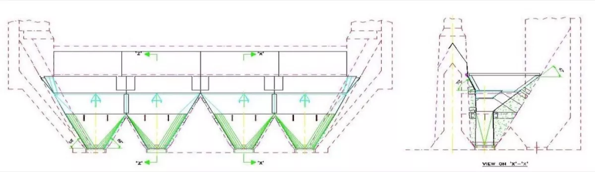
The second mass flow stage expanded the flow channel to a reliable flow width and connected a full row of four outlets together. To destabilise any large rat hole or cliff which might form, a third stage was added which would not mass flow but instead provide self-clearing of the remaining hopper contents. Due to the offset outlet construction, a set of inserts was fitted to reduce compacting pressures in the outlet region and encourage flow from the shallow side of the hopper (Fig. 3).
Performance of Inserts
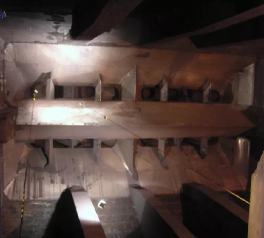
The first row of inserts made such a huge difference to the flow of coal from the bunker; that a financial case was put together to line a further three rows of outlets. There are now two rows of inserts in the 3000-tonne section and two rows in the 1000-tonne section (Fig.4).
Prior to fitting the inserts poking for coal was required at least once per shift from November to March. This is no longer necessary. Moreover, there have been no reportable injuries sustained from poking activities from the service bunker since the inserts were installed in 2009.
When poking for coal there was a tendency for the charge-cars to be under filled. This resulted in the ovens not being filled to the required standard, lower coke yield and subsequent refractory damage to oven chambers. Since the inserts have been installed, better filling of the charge-cars has occurred resulting in improved oven filling and a higher coke yield. The live capacity of the 1000-tonne section is now approaching 80 percent.
In conclusion, powder testing for flow, insert system development using a model and careful consideration of the bunker’s structural integrity, has enabled Tata Steel R,D&T and Ajax Equipment to deliver a successful solution to overcoming earlier flow problems at the Scunthorpe coal bunker.
■
