
(From the archive of ”bulk solids handlingshowthread.php?32098 About the bulk solids handling journal and this archive", article published in Vol. 34 (2014) No. 3 , ©2014 bulk-online.com)The feeder can be subject to quite high overpressures from the hopper contents which can impose heavy shear loads on the feeder. Efficient sizing will limit the load on the feeder and the feeder’s capital cost. The forces acting through the outlet of a bulk storage hopper that has developed a fully mobilised mass flow regime are favourable for reducing the load on the feeder and can be considered to have two components: - that resulting from carrying the unsupported mass underneath the dynamic arch and the extra overpressure resulting from the degree by which the stress developed in the dynamic arch exceeds the unconfined failure stress because the size of the outlet is greater than the critical arching span. Of course to provide an effective mass flow regime it is essential to provide progressive extraction along the hopper outlet slot and generate a shear plane that expands in the direction of travel to relieve the ‘pull-out force’ needed by allowing for expansion and the change of flow direction.
1. Introduction
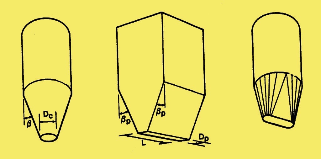
Loose solids are stored in a wide range of hopper shapes and size. A large proportion of these have cylindrical walls because this cross section is effective at resisting the horizontal pressures generated by the material acting on the boundary surface that can be calculated for the vertical walls by the Janssen formula, based on the density and head of material, wall friction and the ratio of vertical to horizontal stresses developed in storage. Container outlets often have a conical hopper section or transform to a slot outlet.Fig. 1 shows some examples. Small outlets can restrict the rate of flow below that required or block, either by lumps jamming together to form a structural blockage or by cohesive products forming stable arches. These hazards are dependent on the interaction of various factors, principally; - the nature of the bulk material, the size and shape of the outlet, the flow regime generated by the vessel geometry leading to the outlet and the rate of flow of the material. The outlet size must exceed the size at which flow stops if the system is to work efficiently but oversizing leads to a high load burden on the feeder and excessive cost.
Guidance on sizing to avoid mechanical arching because of lumps is given elsewhere [1] but the size of hopper outlet needed to avoid the formation of cohesive arches depends on the deformation nature of the bulk material, its frictional resistance on the wall surface and whether the flow channel developed is of converging radial type flow as in a conical hopper, or of planar form as with a wedge shaped convergence. It is also influenced by whether the material is in state of Mass Flow, with slip taking place on the approach walls to the outlet, or whether the flow channel is within a mass of static material. Further, both Mass Flow and Plane Flow have flow advantages over non-Mass Flow and Radial Flow patterns and they both carry various other operational benefits.The problem of cohesive arching was addressed by Jenike, [2], who produced an analysis, test device and design methodology to calculate the ‘critical arching span’ that must be exceeded to secure reliable flow. The procedure for testing the bulk solid and calculating the size of opening needed to avoid cohesive arched forming is well established. Such an arch is only be mobilised when flow initially takes place. However a material forming a stable structural or cohesive arch that negates flow still allows the unsupported load present under the arch to weigh down through the outlet onto the feeder installed underneath. This element is not necessarily significant if the hopper has a circular outlet but if a long slot outlet is used such as in a vee shaped hopper then the load is not insignificant.
2. Flow Patterns
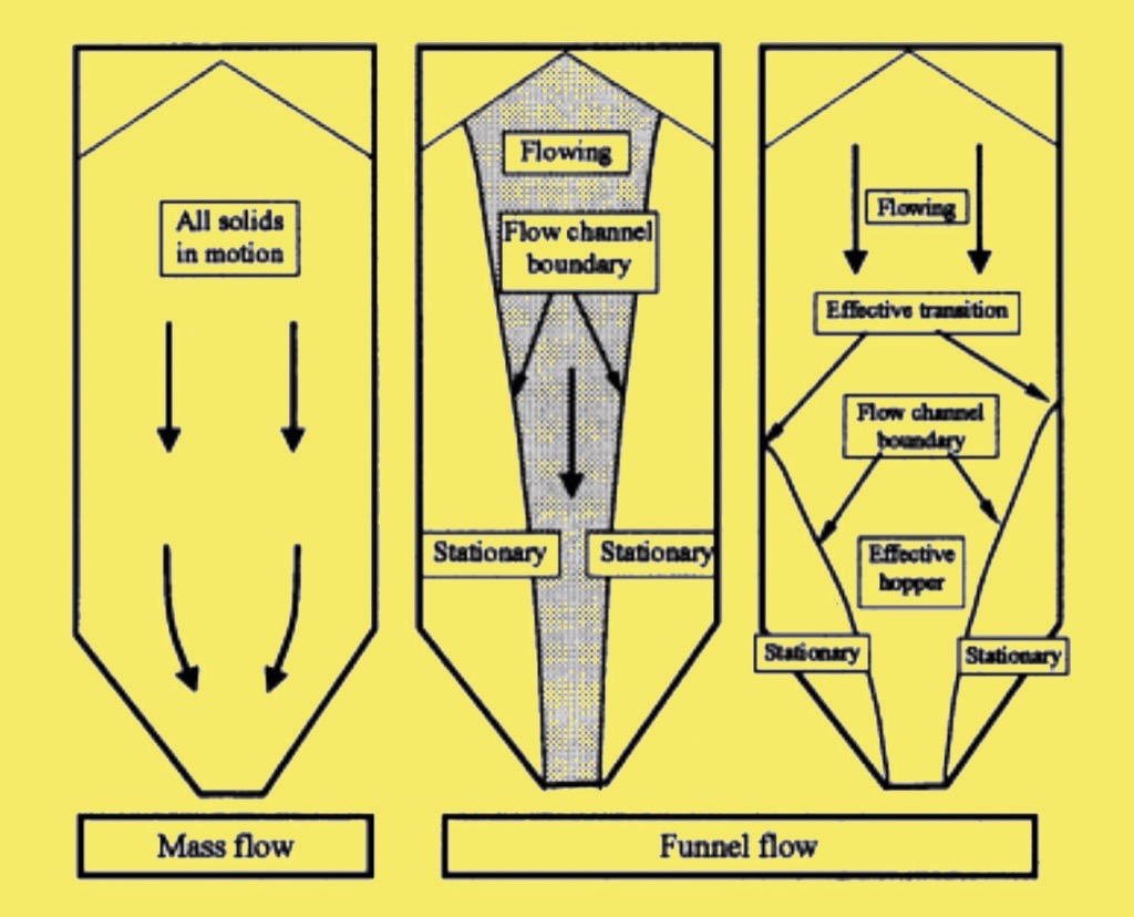
The flow pattern in any hopper, silo or bunker is an important feature that impinges on all aspects of performance, e.g. the loads acting on the structure, the order in which the contents are discharged which may in turn increase segregation. Moreover the flow pattern will influence the size of opening that is needed to ensure that the discharge can be reliably achieved and complete. Flow patterns can generally be classified as either mass flow – where all of the contents moves during any discharge or non mass flow (sometimes called core flow or funnel flow) where a proportion of the contents remain static when discharge takes place [3], Fig. 2.
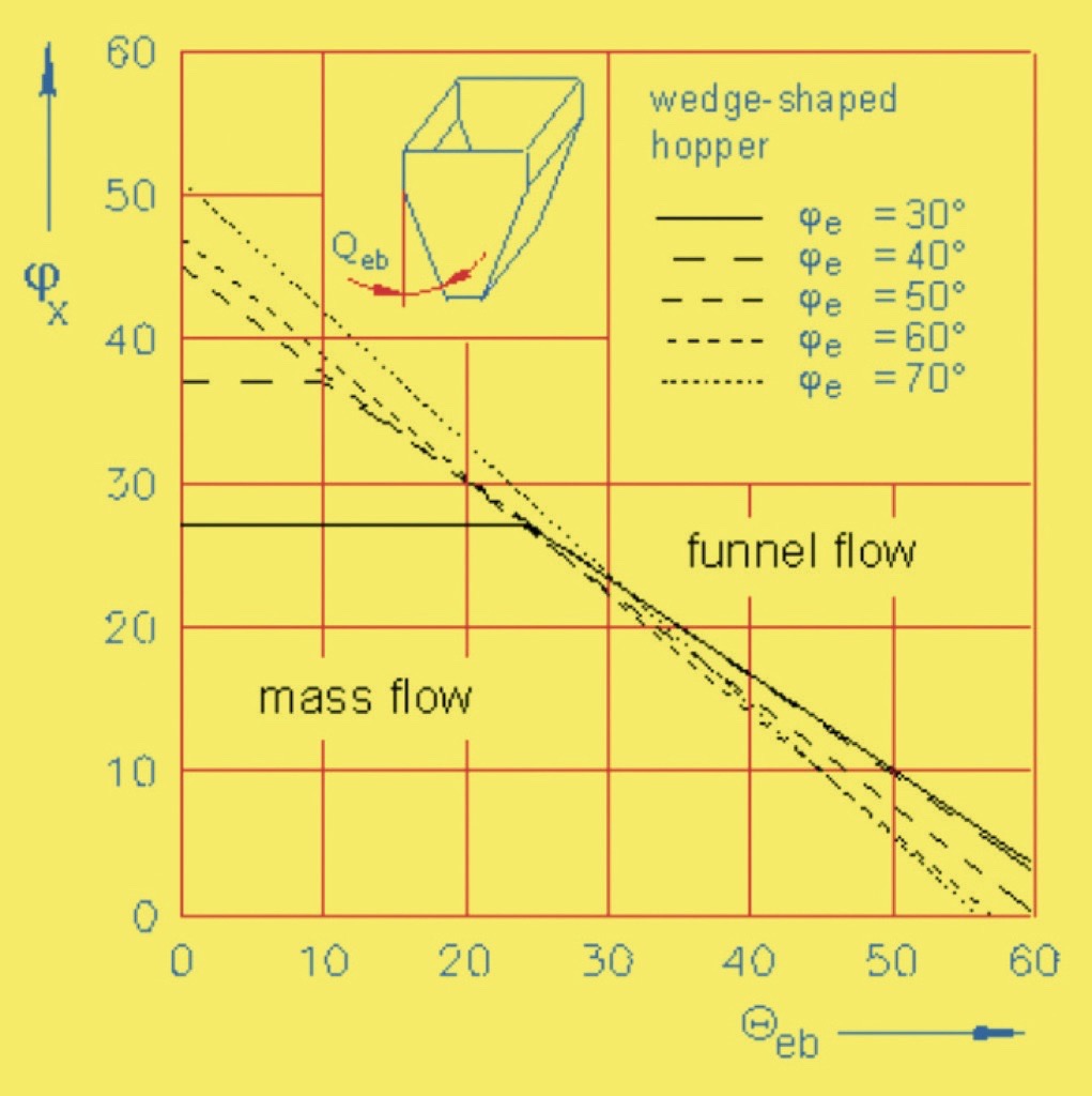
The critical aspect for mass flow is the steepness of wall required for flow. Wall friction measurements are relatively easy to perform and analyse [4]. Charts are available for determining the mass flow hopper slope which also includes consideration of the internal friction angle (Fig. 3) but it is quite possible to make a simple analysis for plane flow hoppers where the slope of hopper to the vertical α, needed for mass flow is dependent only wall friction angle Φ (an easily measured characteristic) by Eq. 1:
| α = 60 – 1.2 ⋅ Φ | 1 |
The other important feature that arises from mass flow design is that the outlet size can be significantly smaller than a hopper that is of non-mass flow form. This can be explained in part because the motion of the total hopper contents during discharge precludes the formation of a stable rat hole. The boundary for mass flow means that a stable arch has to straddle the outlet and without the key of stagnant product this is also far less easily achieved. With the steeper walls that mass flow design inevitably brings there is less support for the contents from the walls and more energy is available for deformation and flow through the outlet. This feature of flow explains the importance of mass flow for efficient outlet sizing. This approach to efficient sizing affects the feeder selection and design too.The stress conditions in the hopper when it is first filled are shown in Fig. 4(left) and are evidently very different to those seen during flow, Fig. 4 from reference [5].
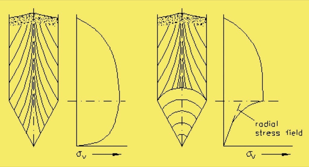
The lines superimposed on the hoppers in Fig. 4 indicate the direction of the major principal stress. In the filling condition the major principal stress is almost vertical due to action of gravity (it diverges slightly due to the friction at the walls). Once the outlet is opened the bulk solid in the converging section can expand vertically but has to compress horizontally. The major principle stress thus switches to the horizontal, arched alignment shown in Fig. 4(right). This indicates that the vertical stress in the converging section during flow is proportional to distance from the apex of the hopper (the radial stress theory, [2]) and is a lot less near the outlet during emptying than at filling (note the wall stress is very much increased during flow and is an important aspect for structural strength of the silo). This switch in flow stresses can be exploited to minimise the feeder load.
3. Loads on Feeders
From Fig. 4 the highest loads will occur following the initial filling of a hopper without any discharge taking place. In addition to these loads the prospects for further less predictable supplementary stresses, for example due to impact loads can combine to generate further effective load on hopper outlet onto the feeder. Good practice dictates that the flow stream should be prevented from impacting directly over the outlet area to prevent inertial forces applying additional compacting loads on the product and outlet area. Apart from increasing the load on the feeder, such conditions will detract from the flow potential of the bulk material. Prior to discharge taking place, the vertical forces reflect the active stresses of storage that may be calculated by the Janssen/Walker equations. Time consolidation would allow further settlement and strength gain to resist flow and resist expansion for easing starting. It is therefore recommended that effective hopper management ensures that some material is drawn off after part loading (ideally as loading occurs) to switch the flow stresses to the passive condition and hence reduce the vertical load on the feeder near the outlet. Furthermore leaving a heel of material from a previous load will both maintain the arched stress running load conditions and shield the feeder form impact loads in subsequent fills.In the limiting case, if the outlet is only just wide enough to support an arch then no vertical stress would bear down at the outlet as the arch would be fully supported from the hopper walls. Whilst unfavourable for flow there would be none) this does indicate that the load on the feeder can be reduced if the outlet size is close to the minimum needed for collapsing of the arch.
4. Arch Form
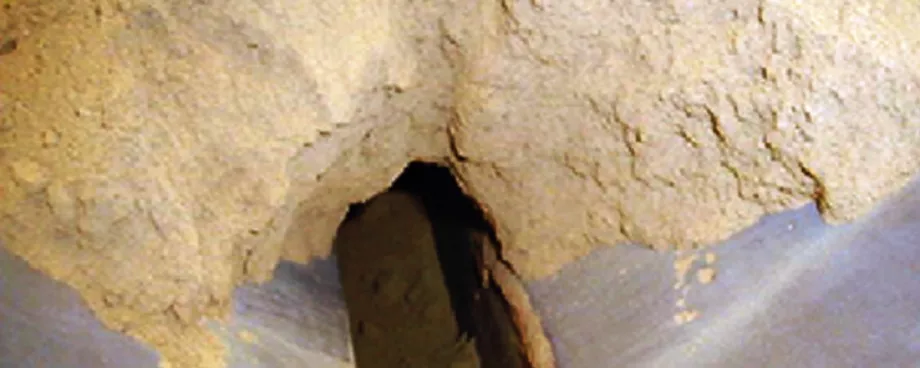
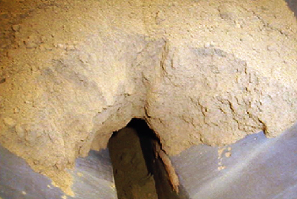
Hooke advised The Royal Society in 1671 [6] that the optimum shape of an arch formed in material of uniform strength and density takes the shape of a catenary curve [3]. As seen in Fig. 5 a real powder arch is so shaped and in line with the stress theory the material will satisfy the uniform density and strength aspects.
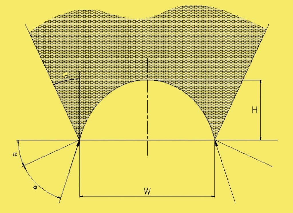
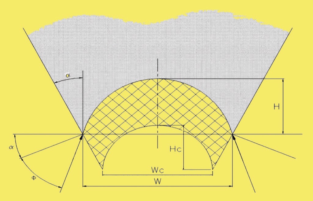
For ease of analysis and practical purposes this shape can be approximated by a parabola, therefore the dynamic load on a feeder during the discharge process of a ‘V’ shaped hopper will be related to the area of material under a failing parabolic shaped arch × the length of the outlet × the density of the product. In the case of such a plane flow hopper, the inclination of the converging walls required to develop mass flow of the contents is mainly a function of the angle of wall friction of the bulk material handled on the hopper walls, as Eq. (1).From Fig. 6, the line of action of the force supporting an arc that is slipping on the walls in mass flow is at an inclination of Φ to the normal of the hopper wall. Hence the tangent to the ends of the arch is at an inclination of Φ + α to the horizontal. The outlet width W, and the slope of tangent to the arch end, uniquely defines the shape of the arch and hence its height at the centre.
The area A under a parabola is
| A = 2/3 ⋅ W ⋅ H |
The height H of the parabola is related to the width W by:
| H = K ⋅ (W/2)2 and dH/dW = 0.5 ⋅ K ⋅ W |
The slope β is:
| β = tan(Φ + α) |
Hence is is:
| H = (W/2)2 ⋅ 2 ⋅ tan(Φ + α)/W |
So Area B under span is:
| B = W2 ⋅ tan(Φ + α)/3 |
The length L of the slot is usually a multiple of W and in any case for flow needs to be at least 3 times the width W. And the material has a bulk density ρ.So the unsupported load is easily established by multiplying area by length L and gravity g. See Eq. (2):
| F = ρ ⋅ g ⋅ L ⋅ W2 ⋅ tan(Φ + α)/3 | 2 |
The load F in Eq. (2) can be shown as a vertical stress σv by diving by outlet area to give Eq. 3:
| σv = ρ ⋅ g ⋅ W ⋅ tan(Φ + α)/3 | 3 |
5. Comparison of ‘in Hopper’ and ‘under Arch’ Loads
It is helpful to review with an example Vee shaped hopper. In this example a 6 m × 1 m long outlet, a 30° hopper half angle and a material being handled with a wall friction angle of 20° and bulk density of 1000 kg/m3. The comparison between the stress levels in the hopper during filling (to a fill height of 9 m) and when switched to flow is shown in Fig. 7.
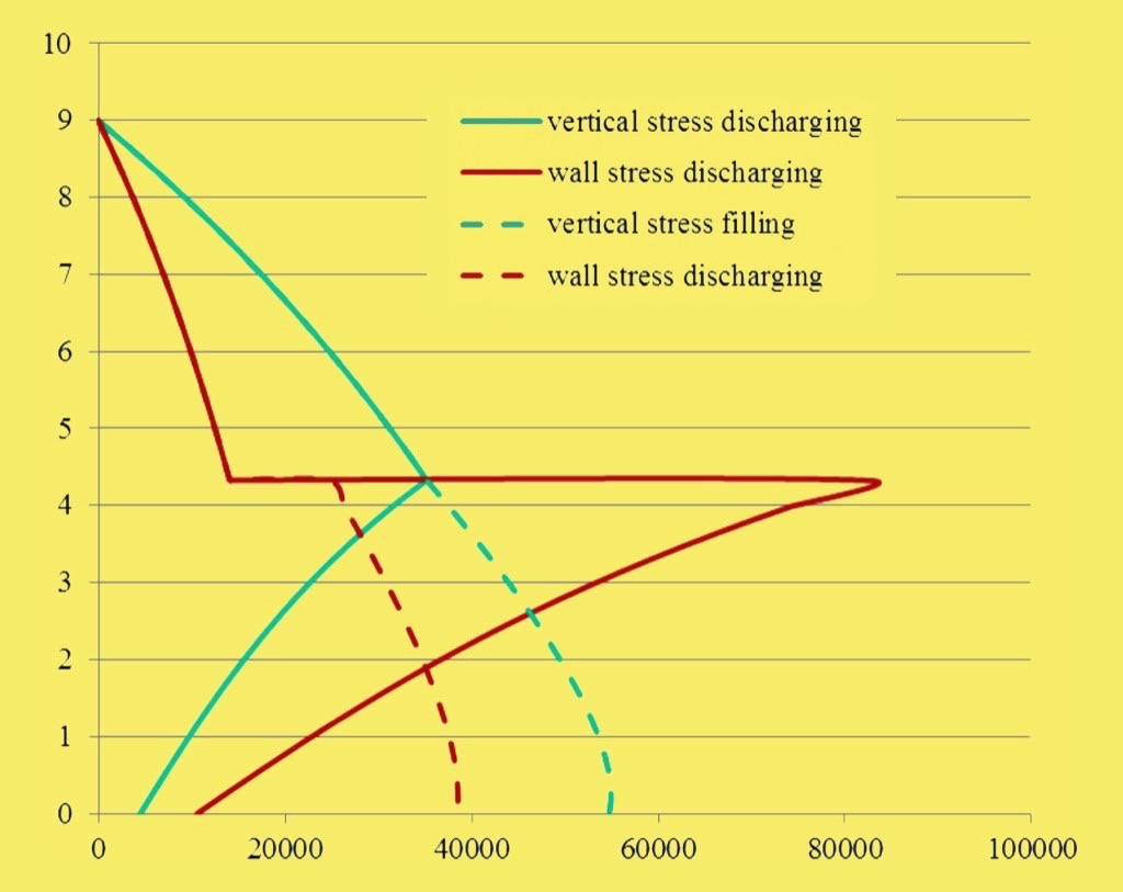
As can be seen the difference between flow stress condition and filling state is dramatic. The vertical stress during flow reduces from 54 kPa to about 4 kPa. This is exemplar in reinforcing the benefits of utilising the flow stress condition (and maintaining it) cannot be overemphasised.Consideration can then be given to the impact that the load due from material under the arch (assuming 1 m is the critical arching width) for materials with different wall friction angle (and hence different parabolas) all in line with Eqs. (2) and (3), see Table 1.
| Wall friction angle [°] | Hopper half angle [°] | Load [N] | Stress [Pa] |
| 25 | 30 | 28563 | 4760 |
| 20 | 30 | 23835 | 3973 |
| 15 | 30 | 20000 | 3333 |
| 10 | 30 | 16782 | 2797 |
It is clear then that the contribution from the material that the mass of material under the arch contributes a similar load to that due from the failing arch and that the wall friction makes a significant difference to the load and stress.If we then optimise the slope of the hopper to the wall angle (so that it is just sufficiently steep to mass flow) then a comparison in loads due under the arch can be made again using the Eqs. (2) and (3), see Table 2.
| Wall friction angle [°] | Hopper half angle [°] | Load [N] | Stress [Pa] |
| 25 | 30 | 28563 | 4760 |
| 20 | 36 | 29651 | 4942 |
| 15 | 42 | 30797 | 5133 |
| 10 | 48 | 32007 | 5334 |
In this case it is then noted that the differences in load or stress are not so very much across the various wall friction characteristics.The fact that these predicted values are lower than forces experienced by many industrial installations reflect the situation that very few hoppers operate with orifice sizes only slightly larger than the critical arching span so an extra pressure acts from the failing arch. The weight of any material occupying the distance from the hopper outlet to the interface with the feeder must also be added to the design load.
6. Consideration of Outlet Sizes larger than Critical Arching Span
A basic reason why hopper outlet sizes are invariably greater than that required to generate reliable flow and pass the rate of discharge necessary is that it is essential to provide a safety factor above the critical arching dimension to accommodate variations in the bulk material or operating circumstances. In practice, larger sizes are also adopted to save headroom, enhance the storage capacity within the available headroom and/or fit a feeding device to secure a controlled discharge rate. For reasons of better flow generation and enhanced storage capacity, the hopper section can also take the form of a transition to a slot outlet, which generates a local plane flow regime. The pressure acting through the outlet of the hopper determines the force acting on the feeder and the drive power requirements of the feeder. The larger the outlet; the greater the potential force that can act through it, so the effect has high significance on large installations. Wider openings cause the failing arch to transmit additional overpressure from the superimposed material; hence a crucial factor that determines the load acting on a feeder is by how much the opening size exceeds the critical arching dimension. The force acting through the outlet from material under the failing arch will still be a function of the parabolic volume of an arch. This component of the feeder loading increases as the square of the outlet width on a plane flow hopper.When flow takes place through an opening larger than the critical span, not only will the unsupported mass under the failing arch increase, but the collapsing arch bears down on any restraining device controlling the discharge. The dynamic arch being in a state of restrained collapse implies that the under-surface is partially confined and the support given to the arch by the material underneath will impose an additional load on the feeder, depending on the amount by which the outlet is larger than the critical arching dimension for flow.An arch larger than the critical span will experience a maximum principle stress greater than the unconfined failure load and be in a state of failure, supported by a force pressing on the underlying material. The amount by which the maximum principle stress exceeds the unconfined failure stress of the bulk material generates a stress acting normal to the arch surface that adds to the weight of the unsupported material under the arch on the outlet. Calculating the maximum principle stress in an arch establishes the critical span, (where this stress is equal to the unconfined failure stress). A similar calculation will determine the maximum principle stress in any larger arch of interest, and hence establish the amount by which this maximum principle stress exceeds the failure strength of the bulk to generate a component of minimal principle stress acting on the unsupported material under the arch.A simpler approach is to consider that at the critical span, any layer of material above a stable arch is supporting the pressure of material above, so, supporting that load must carry the additional force on the outlet from an arch greater than the critical span. i.e. the extra pressure on the outlet due to a large span is the not more than the weight of material in the space between the actual arched stress at the outlet and that of an arch at the critical span, see Fig. 8.
The consequences of the analysis [7] are:
- Load under stressed arch increases as square of width increase.
- Additional load is considered due to collapsing arch.
- Initial width must be greater than critical arching span, normally > 20 %, often much more.
- By way of example therefore if the width increases by 20 %, unsupported load increases by 44 % and an additional load is imposed the by collapsing arch.
The marked distinctive differences between the values this approach will predict and those based on an empirical multiple of the outlet width (is that these increase as a function of the square of the width minus the square of the critical arching span, whereas the empirical values increase linearly, with no consideration of the stressed arch conditions.
7. Some useful Considerations to ease Load on the Feeder
It follows therefore that the recommended design and construction of hopper outlet region should be guided by the following aspects for flow and to minimise loads on the feeder:
- Flow width to exceed critical arching span by comfortable margin only.
- Design for mass flow, (to maximise effectiveness of outlet size and minimise load).
- Outlet length/width ratio to exceed 3:1, (to secure full benefit of plane flow).
- Longitudinal insert, (to reduce overpressure on outlet at large flow area).
- Run off a small amount at an early stage of fill
- Consider fitting a minor flow obstruction or slide gate that can be withdrawn when starting the extraction.
- Ensure feeder offers progressive extraction capability so as to avoid shearing against stationary layer of material above
- If using a belt feeder consider fitting a mechanism to lower the belt before starting.
- Avoid widening hopper outlet as this will increase load (W2) –instead increase depth of extraction for feeder.
- The ‘pull-out’ force of a feeder from a hopper is sensitive to the conditions in the shear plane of flow as it translates from vertical to the horizontal. An efficient interface design must not only provide incremental extraction along the length of the outlet slot from a hopper but must also incorporate continuous dilatation of the bulk solid in the change of flow direction at the hopper outlet, particularly for granular materials that require more dilation to permit the relative motion of the larger particles and avoid jamming at the final exit point from the hopper.
8. Conclusion
Designers should be mindful to not oversize outlets for flow otherwise the design and cost of the feeder will be more than necessary. Additionally running costs will be higher as drives will need to serve the oversized hopper outlet. The minimum requirements are to satisfy flowing condition, as this is the essential job that needs to be done. Fill conditions can put far higher burdens on but these can be managed by mitigation of impact loads and draw off at low fill level to switch to the lesser vertical load condition that flow creates.Even for minimal stressed arch loads designers should be mindful that material under the arch can offer significant load, in some cases comparable with calculated flow loads. It is of course crucial to ensure the outlet is adequately sized and wall slope generates the desired flow regime, ideally mass flow. Whilst it is tempting to be cautious and follow the maxim: ‘if you are a 0.5 hp under sized everyone notices, if you are a hp over no one does’ however these days there is a need to consider IE3 motors and the new efficiency classes as well as the inherent demands that the costs of oversizing will put on the capital plant, its running and the environment.
A Note from the Editor
For all statements in this article that refer – directly or indirectly – to the time of publication (for example “new”, “now”, “present”, but also expressions such as “patent pending”), please keep in mind that this article was originally published in 2014.
References:
- Bates, L.: Size of Hopper Outlet to avoid Blocking by Lumps. Ajax Equipment, 2011.
- Jenike, A.W.: Gravity Flow of Bulk Solids. Bull 123, Utah Exp. Stn, 1964.
- EN1991-4:2006 Eurocode 1: Actions on Structures - Part 4: Silos and Tanks.
- McGee, E., McGlinchey, D.: Using Wall Friction Data to design Hoppers. PARTEC 2004 Nuremberg 2004.
- Schulze, D.: Silo Design and Bulk Solids Flow Properties. From Powder to Bulk, IMechE Conference 2001.
- Hooke, R.: Lectiones Cutlerianæ, or A Ccollection of Lectures: Physical, Mechanical, Geographical, & Astronomical. Linda Hall Library. 2002 – 8, www.lindahall.or, retrieved 2010.11.17.
- McGee, E., Bates, L.: Design Considerations for Hopper Outlet Loads on Feeders. CHoPS 7, Friedrichshafen Germany 2012.
| About the Authors | |
| Dr. Eddie McGeeManaging DirectorAjax Equipment Ltd., United Kingdom | |
| Lyn BatesFounderAjax Equipment Ltd., United Kingdom |
■
