
Bearingless Motor
The rotor is rigidly connected to the drive pulley by means of a flange connection (Figs. 4 and 5).
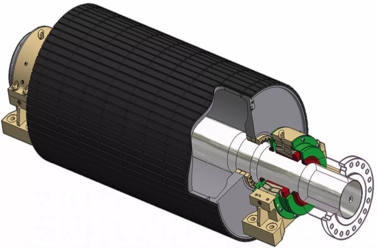
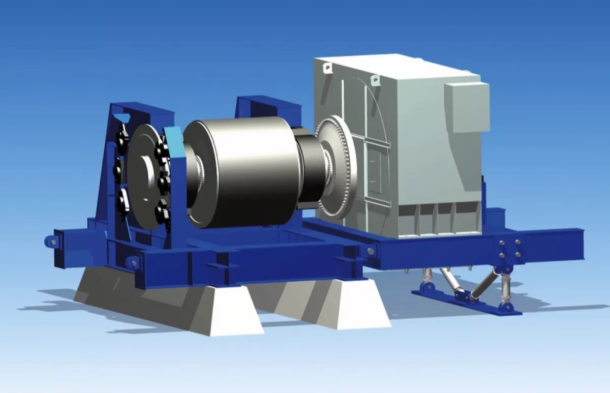
Fig. 4 : Drive pulley with connencting flange for the motors rotor. (Picture: © Takraf)
|
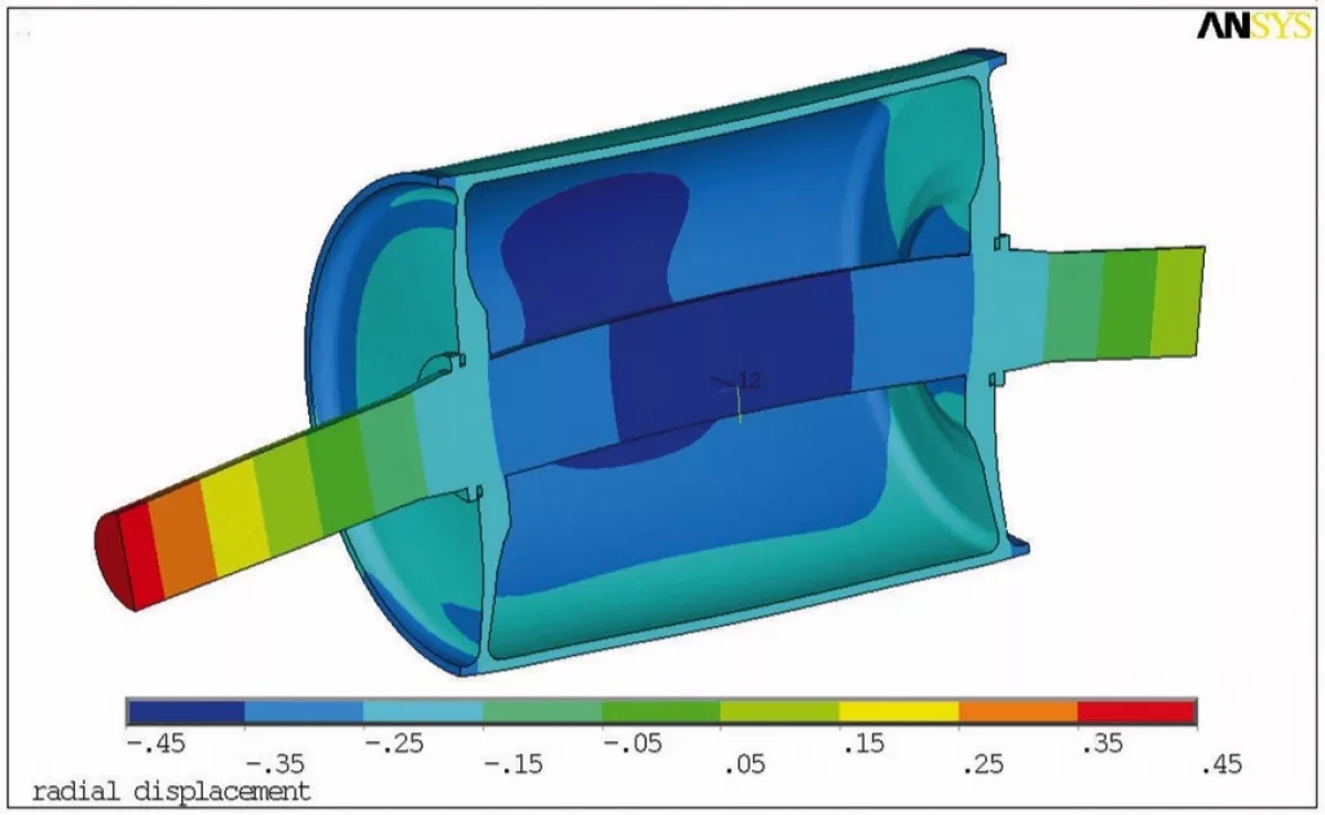
Fig. 5: Deformation at the drive pulley when stressed by driving torque. (Picture: © Takraf)
|
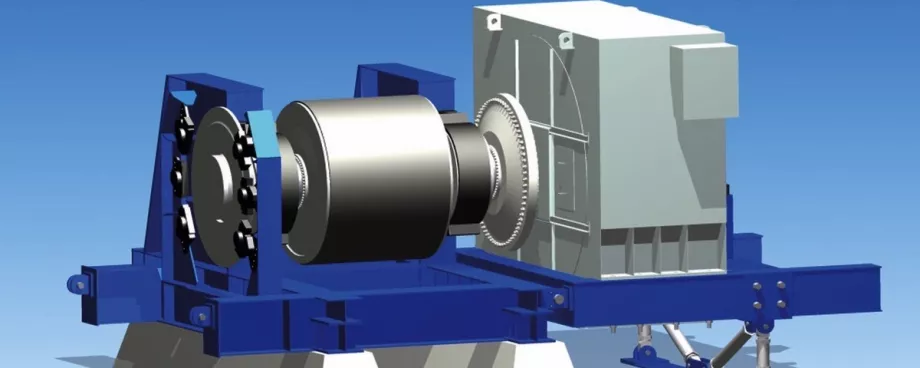
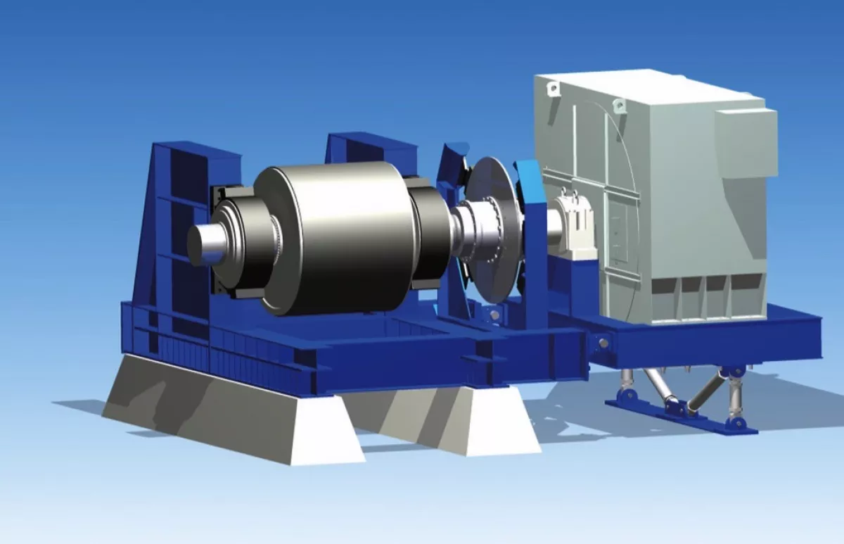
Compared to the standard layout, an additional criterion is necessary for dimensioning the drive pulley. The deflection of the pulley shaft at the coupling flange may not exceed the close tolerances that result from the permissible deviations in the air gap between rotor and stator. That leads to drive pulley structures with large shaft diameters (see Fig. 1). Since the rigidness of the stator mount determines the tolerances in the motors air gap to the same extent, it is necessary to offer solutions with very limited deformations that also allow a subsequent alignment of the stator during commissioning of the conveyor. Drive realignment would be necessary if a proper belt alignment could be reached by drive pulley readjustment only.
Motor with extra Bearing
For the solution previously described, no motor bearings are needed, neither is a special coupling required for connecting the motor to the drive pulley. A rigid flange connection is sufficient. On the other hand, bearingless motors also have disadvantages, such as:
- Special drive pulley design to decrease shaft deflection
- The motor must be assembled on site, since the rotor first has to be connected with the pulley shaft and the stator is then moved over the rotor. This means that the motor must be disassembled again after factory assembly and completion of test run.
- In case of damage, the motor cannot be disconnected quickly and/or replaced with a spare drive.
- For the load case earthquakes, it is necessary to take into consideration the large (rotor) masses at the cantilevered drive shaft end.
The disadvantages described here with regard to bearingless motors have led to working with ABB to design a motor with separate bearings as an alternative.
Diaphragm Coupling
With regard to the bearing motor previously described, the motor and drive pulley are connected by means of a flexible coupling (Fig. 6). A gear coupling was selected as suitable transfer element for the torque being transferred and the permissible angular deviation of both shafts. For very large motors (6000 kW up to 8000 kW of drive power), geared couplings reach their limits. The drive concept with bearingless motors has resulted in heavy and expensive drive pulleys due to the deflection of the pulley shaft in the area of very large drives.
Based on these disadvantages, a motor concept with a bearing at motor N-end and a diaphragm coupling to connect the rotor with the drive pulley was developed. The diaphragm coupling combines the functions of the bearing at the motor D-End and the geared coupling between rotor and pulley (Fig. 7).
To transport the motor, a support structure will be placed on the motor frame, which secures the rotor shaft on the side with the output shaft end. This also provides the option to quickly separate the motor and the drive pulley by opening the coupling in case of an emergency.
Projects
In 2012 Takraf was awarded a contract by the Chilean mine operator Codelco to deliver conveyors with 12 gearless belt drives for the world’s largest underground copper mine (El Teniente). After completion of the conveyor installation, approx. 12000 t/h of copper ore will be transported over a totaldistance of 11.5 km. The drive motors each have an output of 2500 kW. As a result of extensive discussions with the customer, the principle of the motor with separate bearings was implemented for this contract. The commissioning of the first motor is slated for 2014.
Summary
Gearless drives are expanding the service range of drives of belt conveyors. Individual drives with a driving power of up to 8000 kW are possible. Studies on the use of gearless drives of this performance class are currently being carried out in the current projects. When it comes to maintenance and energy efficiency, gearless drives offer advantages compared to the conventional electromechanical solutions. The drive motor can be designed as bearingless, with bearings or with diaphragm coupling. Motor size, site conditions and customer requirements form the basis for the solution that is to be implemented.
A Note from the Editor:
For all statements in this article that refer - directly or indirectly - to the time of publication (for example "new", "now", "present", but also expressions such as "patent pending"), please keep in mind that this article was published in 2014.
■
