

Re: Design Calculations For Pneumatic Conveying
 Originally Posted by Teus Tuinenburg
Edited to make the formula understandable ■
Teus
Re: Design Calculations For Pneumatic Conveying
Originally Posted by Teus TuinenburgEdited to make the formula understandable ■
Teus
Re: Design Calculations For Pneumatic Conveying
Hello Amrit,
I am working on design on dilute and dense phase vacuum conveying systems. I need help in calculating pressure losses in case of dense phase vacuum transfer. I have searched online but i'm not able to find a standard method to do it.
Also it will be great if you can mail me the article on design of dilute phase conveying systems.
my email id: puskar36@gmail.com
Thanks in advance.
Regards,
Puskar
Originally Posted by Amrit Agarwal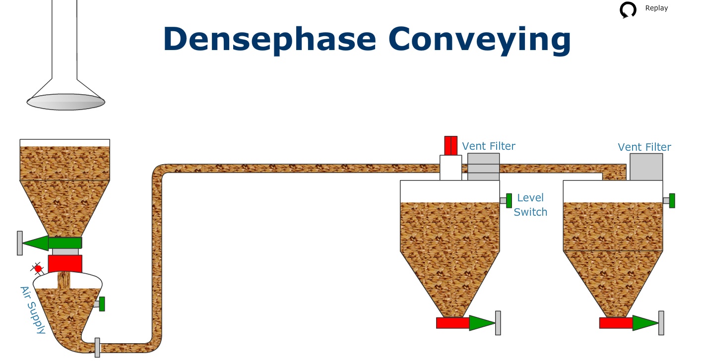
■
Re: Design Calculations For Pneumatic Conveying
Hello Amrit,
I am working on design on dilute and dense phase vacuum conveying systems. I need help in calculating pressure losses in case of dense phase vacuum transfer. I have searched online but i'm not able to find a standard method to do it.
Also it will be great if you can mail me the article on design of dilute phase conveying systems.
my email id: puskar36@gmail.com
Thanks in advance.
Regards,
Puskar
Originally Posted by Amrit Agarwal■
Design Of Dilute Phase Conveying Systems
Originally Posted by puskarpachoriya++++++++++++++++++++++++++++++++++++++++++++++++++++++++++++++++++++++++++++++++++++++++++++++++
Dear Puskar,
I will be glad to send my article for designing dilute phase conveying systems. Please email your request to me.
Regards,
Amrit Agarwal
Consulting Engineer
Pneumatic Conveying Consulting
Charleston, WV, USA
Email: polypcc@aol.com
++++++++++++++++++++++++++++++++++++++++++++++++++++++++++++++++++++++++++++++++++ ■
Calculation Method For Dilute Phase Pneumatic Conveying
Dear Amrit,
Can you send me a copy of the article where in you have given Excel based calculation method for pneumatic conveying.
My email id : ujjwalchowdhury19@gmail.com
Thanks
Ujjwal Chowdhury
Originally Posted by Amrit Agarwal■
Calculation Method For Dilute Phase Pneumatic Conveying
Dear Amrit,
Can you send me a copy of the article where in you have given Excel based calculation method for pneumatic conveying.
My email id : ujjwalchowdhury19@gmail.com
Thanks
Ujjwal Chowdhury
Originally Posted by Amrit Agarwal■
Design Calculations For Pneumatic Conveying Formula
Dear Amrit !
I know it's been a while since this thread was created, this could be a big help with my problem.
May I also request a copy of your article?
my email : Tiendungbkbn@gmail.com
Regards ■
Design Calculations For Pneumatic Conveying Formula
Dear Amrit !
I know it's been a while since this thread was created, this could be a big help with my problem.
May I also request a copy of your article?
my email : Tiendungbkbn@gmail.com
Regards ■
Re: Design Calculations For Pneumatic Conveying
Dear Mr. dungnguyen,
I noticed your request on the bulk online forum for the article od Mr. Agarwal.
From your private message on the bulk online forum, you share some extra information.
Material fly ash (no pneumatic conveying properties given).
Conveying length approx. 100 m (not differentiated in horizontal length and vertical length and number of bends)
Your guesses are a pipeline diameter of 4” or 5” or 6”.
The compressor volume is selected at 60 m3/min. (for all 3 pipe diameters?)
The required capacity is set at 300 tph.
A first indicative calculation shows:
6” pipeline performs 60 tph at 2.5 barg
5” pipeline performs 48 tph at 2.5 barg
4” pipeline performs 29 tph at 2.5 barg
The selected (guessed) pipeline diameters are far too small to reach the required 300 tph.
If this is a serious project, then my advise is to contact your local Atlas Copco agent to for professional support or send a request to simon.van.rompaey@atlascopco.com Antwerp, Belgium. ■
Teus
Re: Design Calculations For Pneumatic Conveying
Dear Mr. dungnguyen,
I noticed your request on the bulk online forum for the article od Mr. Agarwal.
From your private message on the bulk online forum, you share some extra information.
Material fly ash (no pneumatic conveying properties given).
Conveying length approx. 100 m (not differentiated in horizontal length and vertical length and number of bends)
Your guesses are a pipeline diameter of 4” or 5” or 6”.
The compressor volume is selected at 60 m3/min. (for all 3 pipe diameters?)
The required capacity is set at 300 tph.
A first indicative calculation shows:
6” pipeline performs 60 tph at 2.5 barg
5” pipeline performs 48 tph at 2.5 barg
4” pipeline performs 29 tph at 2.5 barg
The selected (guessed) pipeline diameters are far too small to reach the required 300 tph.
If this is a serious project, then my advise is to contact your local Atlas Copco agent to for professional support or send a request to simon.van.rompaey@atlascopco.com Antwerp, Belgium. ■
Teus
Fly Ash Tank
Originally Posted by Teus Tuinenburg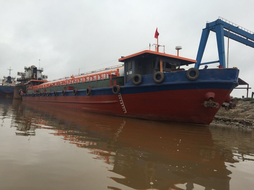
href="showthread.php?p=92822#post92822" rel="nofollow">
Dear Teus Tuinenburg !
Thank you very much for the quick reply
Of course this is a serious project, from my knowledge, and learning in this forum.
we have manufactured and used 750m3 equipment with 4inch pipe and 2.5bar pressure. Currently the capacity is about 50tph per line (90-100tph if use 2 line discharge). From there I want to increase the capacity with 1250m3 equipment and 6inch pipes, 2.5 bar pressure. 60m3 air flow is for 6 inch case with 4 pipes (each exhaust will provide 75tph capacity).
I would like to ask for your opinion, or your calculation to limit the occurrence of congestion, not ensuring enough wind flow or not enough capacity.
Thank you very much for your knowledge.
href="https://forum.bulk-online.com/attachment.php?attachmentid=48215&d=1650104962" title="Name: z3344721528869e2df0806a0c593c8666c0f04a59e43e0.jpgViews: 14Size: 81.1 KB">z3344721528869e2df0806a0c593c8666c0f04a59e43e0.jpg ■
How To Calculate Method
my knowledge is still too little with this pneumatic conveying, from what can be tracked, your knowledge helps me a lot. If possible, can you give me a part of your calculation in excel for my reference. Of course if it's a secret I can understand if you can't help.
my email : tiendungbkbn@gmail.com
I wish you all the best ■
Re: Design Calculations For Pneumatic Conveying
Dear Mr. dungnguyen,
Of course, this is a serious project, from my knowledge, and learning in this forum.
Is this a serious project for you to learn or is it a serious project, which will be executed?
4inch pipe and 2.5bar pressure. Currently the capacity is about 50tph per line (90-100tph if use 2 line discharge).
If the conveying length of this system is the same system, which I calculated 100m horizontal, 40 m vertical and 20 bends, there is a difference in calculated capacity and claimed capacity.
Due to insufficient data, it is not possible to find the cause of the difference.
From there I want to increase the capacity with 1250m3 equipment and 6inch pipes, 2.5 bar pressure. 60m3 air flow is for 6 inch case with 4 pipes (each exhaust will provide 75tph capacity).
I calculated for 4 6” pipelines a combined capacity of 4 x 60 = 240 tph. (Then you need 4 separate tanks and 4 compressors)
Again, the calculated capacity is a preliminary one and not reflecting a final design.
From the picture in your thread, I assume that the project concerns a fly ash tanker barge with one horizontal pressure tank with a working pressure of 2.5 barg.
Operating 1 pressure tank with 4 outlets is not a stable situation.
If one of the outlets is not conveying fly ash, the other outlets lose the airflow and get choked.
Then you have multiple, 100 m long problems.
Designing a pneumatic conveying system requires in depth knowledge how a system functions in all stages and calculations require software, based on the understanding of the physical laws (gas laws, Newton, thermodynamics, conservation of energy, flow dynamics and the mathematical description of all those physics)
If possible, can you give me a part of your calculation in excel for my reference.
The calculation is not in Excel. The software is not available on the market.
Again, if this is a serious project to be executed, then my advice is to contact your local Atlas Copco agent to for professional support or send a request to simon.van.rompaey@atlascopco.com Antwerp, Belgium. ■
Teus
Hmm
Thanks for your comments, I will think about these suggestions. for some reason I'm still thinking of a system with one tank and 3-4 discharge lines to increase capacity. if it really doesn't work, it will be a math problem that I can't find the answer to ■
Hmm
Thanks for your comments, I will think about these suggestions. for some reason I'm still thinking of a system with one tank and 3-4 discharge lines to increase capacity. if it really doesn't work, it will be a math problem that I can't find the answer to ■
Re: Design Calculations For Pneumatic Conveying
Dear Mr. dungnguyen,
Thanks for your comments, I will think about these suggestions. for some reason I'm still thinking of a system with one tank and 3-4 discharge lines to increase capacity. if it really doesn't work, it will be a math problem that I can't find the answer to
Assume that you have 4 parallel lines operating from one common pressure tank.
And assume that the 4 pipelines have the same diameter, horizontal length, vertical length and the same number of bends.
The 4 pipelines will convey the equal amount of fly ash because the conveying pressure for all pipelines is equal and the airflow is equally divided over the pipelines.
If the feeding of one of the pipelines is changing (f.i. an irregular feeding flow or one pipeline is not getting any fly ash at all, because that section is empty) then the 4 pipelines still experience the same tank pressure.
But the requirement of equal airflow for the 4 pipelines can no longer be met.
The pipeline which is not getting any fly ash feeding becomes an open line with a low airflow resistance and draws all the air, leaving not enough air for the other lines.
In the other lines the airflow drops and the air velocity in those lines reduce to a level that the fly ash can no longer be kept in suspension, resulting in a full choke.
If it really doesn't work, it will be a math problem that I can't find the answer to
This is not a situation that can be solved by mathematics. ■
Teus
Pneumatic Conveying Using Blow Through Valve
We have stored Non hygroscopic, self compacting, dry powder (fly ash) (Bulk Density-800 kg / cum) and ( 0 to 200 micron - d50=45 micron) in Bulk bag - 1000 kg
We have 9 cubic meter hopper. We are using hoist to lift bulk bag and pneumatic massager to empty bulk bag in the hopper.
Below the 9 cubic meter hopper we have a BLOW THROUGH VALVE (350 MM ROTOR DIA) 130 mm pipe line.
The material conveying pipe line has 6 bends, 23 meter vertical distance and 28 meter horizontal distance.
We have connected Hyva blower (Centrifugal) of 850 cum and + 1 kg/sq. cm pressure. Motor 37 kw.
Hyva air is connected to the Blow through valve.
The material is not getting conveyed.
First 5 meter pipe is 130 mm, then there is 4 meter long flexible hose of 140 mm, rest is the 150 mm pipe line. Bends are 5d with DRC wear lining
Expected conveying rate is 10 TPH.
What is the problem of system design?
Is the pressure of the blower correct?
Is the air flow of the blower sufficient?
Is the material conveying line design a problem?
What are the possible solutions to make it operational.
Vipin Dave
vipindave1851@gmail.com
Ahmedabad, India ■
Re: Design Calculations For Pneumatic Conveying
Dear Vipin Dave,
Design is 34 tph at 0.236 m3/sec at 1 bag (at sea level)
Is the pressure of the blower correct? Is the air flow of the blower sufficient?
Depends on the blower characteristic. (could not find that on the internet)
Is the blower characteristic given as:
850 cum at 0 barg
And
0 cum at 1 barg
No, the material conveying line design is not a problem.
It seems that the rotary valve is over feeding the system and that the blower curve delivers not enough air flow at 1 barg
What are the possible solutions to make it operational.
A PD blower is a better choice than a centrifugal fan, due to the respective characteristics.
A VFD drive on the rotary valve from zero to maximum and probably a smaller blower. ■
Teus

Design Calculations for Pneumatic Conveying
My article "Theory and Design of Dilute Phase Pneumatic Conveying Systems" was published this month in
href="https://who.bulk-online.com/profile/2-reinhard-h-wohlbier.html" target="blank">Powder Handling and Processing magazine. This article gives an easy to use Excel-based calculation method for designing new dilute phase pneumatic conveying systems or for improving the performance of existing conveying systems.
Regards,
Amrit T. Agarwal
Consulting Engineer
Pneumatic Conveying Consulting Services
Email:
href="mailto:polypcc@aol.com">polypcc@aol.com
Ph and Fax: 304 346 5125
Picture added by Adinistrator as an example:
href="https://forum.bulk-online.com/attachment.php?attachmentid=42181&d=1415730847" id="attachment42181" rel="Lightbox14426" target="blank"> ■
■