
(From the archive of ”bulk solids handling", article published in Vol. 35 (2015) No. 2 , ©2015 bulk-online.com)
Introduction
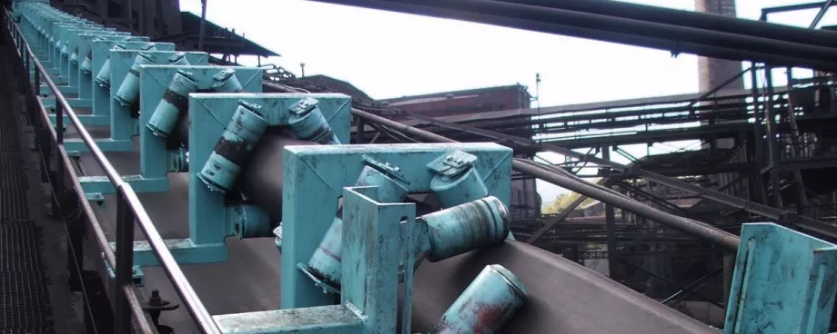
The pipe conveyor represents a progressive transport and handling medium, which is developed for the continual transport of solid bulk materials. This special type of belt conveyor is applied in a wide range of various industrial technologies. Nevertheless, there are still remaining many unanswered questions concerning the pipe conveyor operation as well as questions relating to the maintenance, reliability and durability of the pipe conveyor belt. A number of different scientific methods, together with their modifications, are used in order to find out answers to the above-mentioned questions. One of the most often exploited methods, which is proven within the framework of a quantitative research, is the experimental method.The experimental method (or briefly „experiment“) plays an important role among the methods of quantitative research oriented into the area of pipe conveyors because it is the only one of the research methods, which is able to verify the causal consequences of the individual operational parameters and characteristics [1, 2].This method is able to demonstrate, how one of the operational phenomena influences the other one, etc. [3] The other research methods that are used for investigation of the pipe conveyors enable to determine mutual relations among the individual phenomena, however they are not able to verify whether these interrelations are causal or not.Realisation of the experimental measurements on the current operational conditions of the real pipe conveyors is a very demanding task and sometimes the real measurement is almost impossible due to various reasons. A suitable solution of this problem offers application of a special testing stand, which enables to perform a wide range of the experimental measurements [4, 5]. One such stand was developed at the Technical University of Kosice [6]. During the process of development and calibration of this stand a FEM (Finite Element Method) model was created and applied, which offers a possibility to simulate the real pipe conveyor.
1. The Calculation Model
The calculation model, which is based on the FEM, was created in order to determine conditions or relations concerning forces that are occurring during the real pipe conveyor operation, and the above-mentioned testing stand was designed according to the determined relations. At the same time the measuring strain gauges were selected and calibrated.
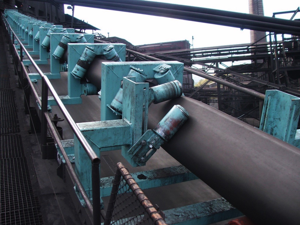
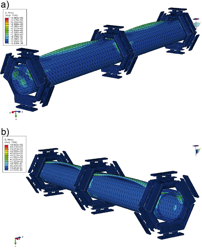
The calculation model represents a separated straight section of the real pipe conveyor (Fig. 1). The calculation procedure was realised by means of the software tool Abaqus, whereas during performing of the calculation it was considered a non-linear process, using the ABAQUS/Explicit software. The calculation procedure was divided into several steps. The explicit method is a suitable tool for solution of difficult tasks [7]. The corresponding geometrical model is created so that it represents a linear segment of the pipe conveyor, whereas this segment can be situated anywhere in the straight section of the pipe conveyor trajectory (Fig. 1).Within the geometrical model the idler housings are simulated, which are typical for the pipe conveyor, i.e. the idler housings with 6 mounted idler rolls (three idler rolls are situated on one side and the other three idler rolls on the opposite side of the idler housing).
2. Material Characteristics of Conveyor Belt
In order to create the calculation model and to perform the experiment it was simulated the real type of the conveyor beltEP 500/3HP 5+3. Determination of the relevant material characteristics of the pipe conveyor belt is based on internal structure of the belt itself. The main material of the conveyor belt is rubber, of course.
| Material density of the conveyor belt ρ (kg/m3) | 1099.7132 |
| Poisson number μ (-) | 0.499 |
| Modulus of elasticity in a shear G (MPa) | 2.9 |
| Young’s modulus of elasticity of belt E1 (MPa) | 397.6429 |
| Young’s modulus of elasticity of belt E2 (MPa) | 6.501602047 |
The rubber is a material with a highly non-linear behaviour, which is difficult to be characterized exactly. That is why any mathematical process, which has to simulate this material, is very problematic and complicated. The rubber is considered as hyper-elastic material.In addition, the rubber conveyor belt also contains internal reinforcing elements, which are affecting the local stiffness properties of the belt and thus make it more difficult to define characteristics of the conveyor belt as a whole.In general, it can be said that the conveyor belt is a composite material, i.e. it is such material, which is made up of several internal layers, whereby the individual layers are different in their material characteristics. Therefore the conveyor belt characteristics are varied as a whole in the lengthwise and crosswise directions.Thus, the provided material characteristics were verified by testing the troughability and by determining the maximum deflection of the belt material.The main principle of the troughability test consists in measuring of the size of deformation for the conveyor belt sample. The measured deformation is caused by the belt’s own weight, without reaction of external forces (Fig. 2a). The sample is suspended from both ends so that the side edges are in the same horizontal plane.
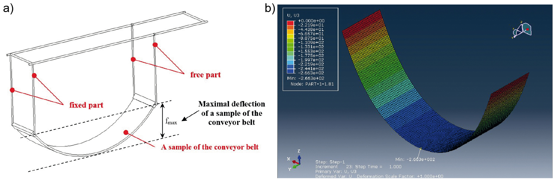
While testing, the maximum deflection at the centre of the sample is measured after 300 seconds. As a part of the verification, the results obtained by means of the experimental measurements were compared with the FEM calculation performed in the program Abaqus. The length of the geometrical model, which was used in the calculation, is 150 mm and its width is 800 mm (the same as the width of the real conveyor belt).The model was created or assembled from the finite elements of the type S4R Shell. It is a 4-node doubly curved thin or thick shell, reduced integration, hourglass control and finite membrane strains. Marginal conditions were defined so that one end of the sample has reduced degrees of freedom in direction of the axes x, y, z and the other end of the sample has reduced degrees of freedom in direction of the axes y, z.The result of calculation of the troughability test is the computed value of the sample deflection fmax = 266.3 mm (Fig. 2b). The sample deflection value determined by the experimental measurement was fmax = 266.4 mm. So it is proved that the difference between the results of the computational and experimental measurement is 0.0037 %.Within the calculation model the shell elements of the type S4R (4-node doubly curved thin or thick shell, reduced integration, hourglass control, finite membrane strains) were used in order to generate the finite element network.Two contact pairs were defined in the computational model. The first contact pair is created from the forming rollers placed in the idler housing and from the conveyor belt. The second contact pair is the conveyor belt itself, which is contacting both own ends each other after forming of the belt into the piped shape.The “General Contact” function was used in order to define the above-mentioned contact pairs. It is possible to say that the contact interactions are defined typically by specifying of a self-contact using the software tool Abaqus/Explicit, which includes all bodies in the model and it defines the element-based surface automatically. The general contact algorithm is usually faster than the contact pair algorithm and it is modified towards the models with multiple components and with a complex topology. The contact algorithm created in the Abaqus/Explicit is specified as part of the model. It allows a very simple definition of the contact relations with only very few restrictions concerning types of the involved surfaces. It uses sophisticated tracking algorithms so as to ensure that the proper contact conditions are established efficiently. The general contact can be used simultaneously with the contact pair algorithm (i.e., some interactions can be modelled with the general contact algorithm, while others are modelled with the contact pair algorithm).The marginal conditions, determined according to the computational model, were defined in such way that the idler rolls, representing the idler housing, have removed all degrees of freedom. The conveyor belt is placed in front of the idler housing and because of the defined displacement during the calculation it moves to a specified position.The conveyor belt model was loaded with additional torques, which ensure forming of the conveyor belt into the piped shape for a correct positioning of the belt in the idler housing. After setting of the conveyor belt into the required position in the idler housing, the belt is released. In this way the idler rolls are setting into the correct operational position. Furthermore, the conveyor belt is still loaded by the tensioning force and gravity.
3. Contact Force Effects between the Belt and Forming Idlers - Calculation
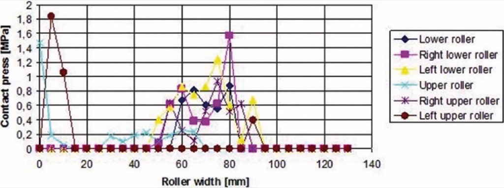
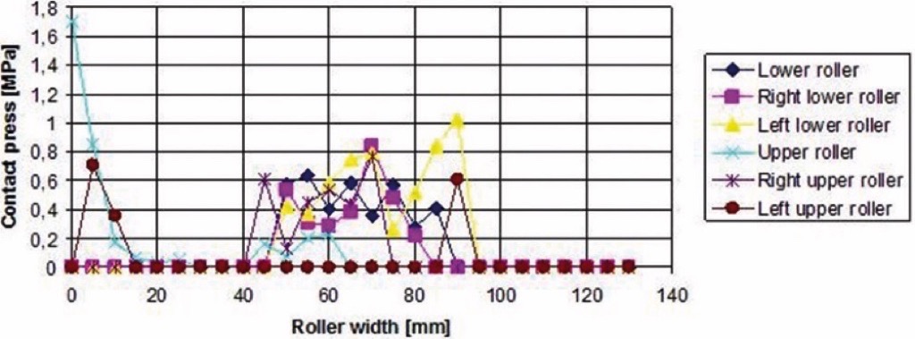
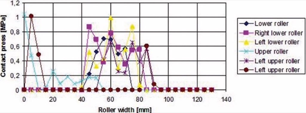
The calculation results describe tension stress state in the conveyor belt as well as value of distortions and particularly also interaction among the conveyor belt and forming rollers arranged in the ring (or hexagonal) idler housing, which consists of two idler roll triplets.The piped form of the conveyor belt is a result of the belt positioning among the forming idler rolls that are situated in the idler housing. An interaction between the conveyor belt and the forming idler rolls is occurring in the point of a contact between the conveyor belt and each of the idler rolls. As a result of this process there are generated the motional resistances, which have to be overcome. The higher is value of the motional resistances, the higher is also of energy consumption, which is required for driving of the pipe conveyor. Another negative influence of the motional resistances is a more intensive wear-out process of the conveyor belt and bearings supporting the forming idler rolls. The graphical illustration of the calculated contact force effects, which are presented in the form of the contact press values between the piped conveyor belt and the individual forming rollers, is in Figs. 3 - 5.
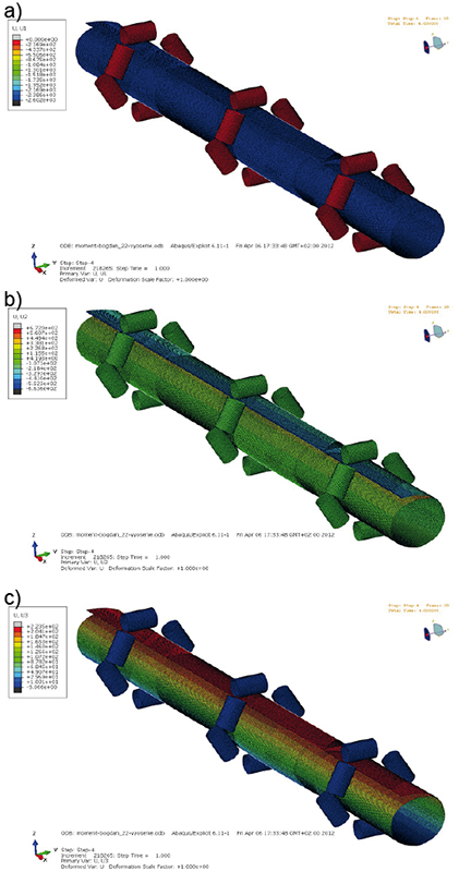
During a current operation of the pipe conveyor, the shape of conveyor belt is transforming periodically from the flat form (on the head pulley and tail pulley) to the piped form. The torsion deformations occurring during this whole periodical process are illustrated in the Fig. 6 by means of the partial deformations in directions of the axes X, Y, Z.
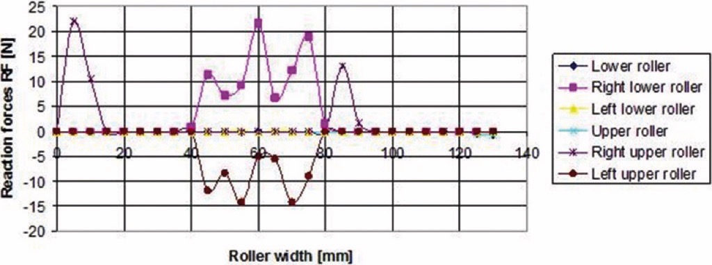
At the same time, movement of the conveyor belt through the round idler housing induces force reactions, which are acting on the forming rollers. The values of reaction forces (RF) occurring on the individual idler rolls in the 1st idler housing are presented in the Fig. 7.
Conclusion
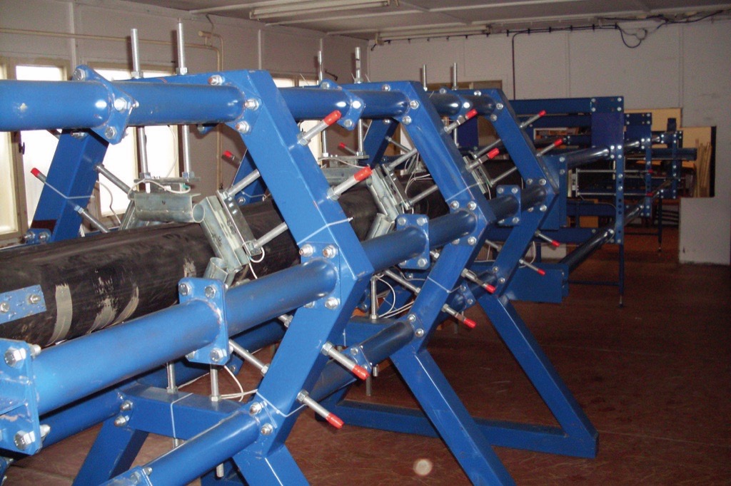
Development and design of the test stand (Fig. 8), which simulates a real pipe conveyor, was enabled thanks to information obtained from the described FEM calculation model.
This test stand enables to determine the contact forces that are induced due to forming of the conveyor belt into the pipe shape. Information concerning values of the contact forces between the conveyor belt and the forming idler rolls allows to perform a research, which is focused on interaction between two subjects: the conveyor belt and the forming idler rolls placed in the idler housing of the pipe conveyor.Another advantage, which is resulting from this simulation model, is a fact that it allows to fulfil a deeper investigation, together with more detailed analysis of the pipe conveyor sample as well as to verify existence of the movement resistances and contact forces in the pipe conveyor idler housings. The computational model is specified with regard to the research conditions, in order to investigate influences affecting size of the movement resistances and the contact forces during the pipe conveyor operation. Thus, the obtained information can be used for dimensioning of the pipe conveyor drives, for selection of the conveyor belt, idler rolls, etc. Simultaneously, it was also developed another computational model according to the obtained experiences and knowledge. However, it is a model of the testing equipment itself.This model, together with the test stand, enables to perform a more detailed scientific research of the movement resistances and the contact forces arising in the pipe conveyor idler housings, Fig. 9. Knowledge of the movement resistances and contact forces has predominant influence on design of the conveyor drive and on selection of a suitable conveyor belt structure. These factors are relevant in the design process of the pipe conveyor and they have a direct impact on the operational costs; however significant is also their impact on the conveyor belt durability.
It is possible to say that the correct understanding to the movement resistances and contact forces has a potential to bring significant financial savings to the operator of such continuous transport system for bulk materials. The presented model and calculation methodology can also be helpful in the process of a new structural design of the pipe conveyor belts, for a selection of internal layer structure of the conveyor belt, for a choice and composition of the rubber compounds, etc.Another important reason for ongoing investigation of the contact forces and movement resistances in the area of pipe conveyors is a substantial fact that these aspects are influenc-ing the durability or technical life of the conveyor belt very significantly.Every possible prolongation of the conveyor belt technical life is associated with relevant economical savings, because the new belt is an expensive financial item usually, what often represents unplanned expenditures to the belt conveyor operator. A necessity of the conveyor belt replacement may lead to consequential economical losses, even to a temporary closure of the given technological facility.
Acknowledgements:
This work is a part of research projects VEGA 1/0922/12, VEGA 1/0258/14, VEGA 1/0197/14 and project APVV SK-CZ-2013-0169.
References:
- Zamiralova, M.E., F. Van Keulen, G. Lodewijks: A new analytical approach to calculate the idler roll load distribution of a pipe conveyor; in: ICBMH 2013 - 11th Int. Conf. Bulk Mater. Storage, Handl. Transp., 2013. http://www.scopus.com/inward/record.url?eid=2-s2.0-84890044579&partnerID=40&md5=9d56d6bbcaea33d77055239a51039cb0.
- Rozbroj, J., J. Zegzulka, J. Nečas: Use of DEM in the Determination of Friction Parameters on a Physical Comparative Model of a Vertical Screw Conveyor; Chem. Biochem. Eng. Q. 29 (2015) 25–34. doi:10.15255/CABEQ.2014.2142.
- Petrikova, I., B. Marvalova, S. Samal, M. Cadek: Digital Image Correlation as a Measurement Tool for Large Deformations of a Conveyor Belt; Appl. Mech. Mater. 732 (2015) 77–80. doi:10.4028/www.scientific.net/AMM.732.77.
- Mazurkiewicz, D.: Problems of numerical simulation of stress and strain in the area of the adhesive-bonded joint of a conveyor belt; Arch. Civ. Mech. Eng. 9 (2009) 75–91. doi:10.1016/S1644-9665(12)60061-2.
- Strohmandl, J.: Use of simulation to reduction of faulty products, UPB Sci. Bull. Ser. D Mech. Eng. 76 (2014) 223–230.
- Michalik, P., J. Zajac: Using of computer integrated system for static tests of pipe conveyer belts; in: 13th Int. Carpathian Control Conf. (ICCC), 2012, IEEE, High Tatras, 2012: pp. 480–485. doi:10.1109/CarpathianCC.2012.6228691.
- Sun, J.S. K.H. Lee, H.P. Lee: Comparison of implicit and explicit finite element methods for dynamic problems; J. Mater. Process. Technol. 105 (2000) 110–118. doi:10.1016/S0924-0136(00)00580-X.
| About the Authors | |
 Prof. Gabriel FedorkoProfessor Gabriel Fedorko works at the Logistics Institute of industry and transport, Faculty BERG, Technical University of Kosice as Head of Logistics Institute of Industry and Transport. Within his scientific research activities he devotes himself to modeling and simulation of ecological transport systems. Prof. Gabriel FedorkoProfessor Gabriel Fedorko works at the Logistics Institute of industry and transport, Faculty BERG, Technical University of Kosice as Head of Logistics Institute of Industry and Transport. Within his scientific research activities he devotes himself to modeling and simulation of ecological transport systems. |
|
 Assoc. Prof Vieroslav MolnárAssoc. Professor Vieroslav Molnár works at the Logistics Institute of industry and transport, Faculty BERG, Technical University of Kosice as Head of Division of Transport. His research interests include the steel ropes and pipe conveyors simulated by CAD systems Catia and Creo. Assoc. Prof Vieroslav MolnárAssoc. Professor Vieroslav Molnár works at the Logistics Institute of industry and transport, Faculty BERG, Technical University of Kosice as Head of Division of Transport. His research interests include the steel ropes and pipe conveyors simulated by CAD systems Catia and Creo. |
|
 Ing. Melichar Kopas, PhDIng. Melichar Kopas, PhD. is an assistant lecturer at the Department of Engineering for Machine Design, Automotive & Transport, Faculty of Mechanical Engineering, Technical University of Košice. His research interests include drive mechanisms and transmissions for transport and handling machinery as well as theory and construction of mechanical conveyors for bulk solids. Ing. Melichar Kopas, PhDIng. Melichar Kopas, PhD. is an assistant lecturer at the Department of Engineering for Machine Design, Automotive & Transport, Faculty of Mechanical Engineering, Technical University of Košice. His research interests include drive mechanisms and transmissions for transport and handling machinery as well as theory and construction of mechanical conveyors for bulk solids. |
■

