

Re: Pneumatic Conveyor Pipeline Sizing
The distance is more critical if the convey length is long. More differential pressure at pick up results in lower pick up velocity if not sized properly. I would allow at least 5 feet after pick up. If this is not possible, then place an elbow in the horizontal plane, place long horizontal run, then elbow up to the vertical. Use an elbow with 12X the pipe diameter. Note, you should reconsider the line size you have chosen. A 5" convey line will work better if you are going 100 foot or more.
Peter Hoefler
HAF Equipment
Centerville, MN ■
Re: Pneumatic Conveyor Pipeline Sizing
Originally posted by Don L
I am currently designing a system to pneumatically transport Sodium Sulphate from a silo via a rotary valve to another storage vessel. Approx 9 tph.
Is there a specific length of straight pipe ( ie 10x dia?) that I should have after the rotary valve and before the first 90 degree bend. We have space constraints which means we are planning to go straight from the rotary valve to a 90 degree bend, going vertical. I am using a 100mm dia stainless steel pipe with 1000mm radius bend. (10x dia, rad).
I would appreciate any advice you can offer.
First things first.
You have not mentioned whether you will be using dense or dilute phase conveying for your sodium sulphate as this is the first stop at the algebra problem.
second: can you change the direction of the piping to allow for a shallow rise and run/slope?
total distance including elbows, desired flow rates etc
the roots tables will help you or my friend Teus will gladly help.
Every curve or need to propel the material upward will cost you huge amounts of energy/power to move the material from a to b.
Resistance AKA gravity, pipe friction at the elbows, product size, power available to operate the blower, year round ambient temperature, The elbows will probably be the first things to go bad from friction so plan on having elbows that are bolted to flanges and a rotary valve that can be bolted and unbolted into place for repair and replacement
Boyles gas law and a good local rotary lobe blower representative/supplier will help you size the proper blower for this if the route of the pipe is unchangeable
Google Roots Blowers and they have a lot of useable information
and tables of distances for propelling materials for their line of blowers as do many other manufacturers.
lzaharis ■
System Design And Supply
As you are located in New Zealand, Please contact us at Nu-Con-Auckland
for Suitable design of system suppy of components etc.
BV Sarma
Regional Sales Manager
Nu-Con Limited
20, Fairfax Ave
Penrose
Auckland
0064-9-5792044- extn 216 ■
Pneumatic Conveying Line
The location of the first elbow is more critical on aggressively designed systems (long distance, high material-to-air ratios) than more conservatively sized ones. Picture that the airstream must fully entrain the material prior to the elbow in order to efficiently pass through the elbow without disentraining the product. More heavily loaded pipes require a longer acceleration length.
Min of 5 ft (preferrably 10) would be the normal recommendation.
If this is not possible in your line layout, you can "cheat" by decreasing the line size of the pick-up and first elbow and then step to the original pipe size 5-10 ft later. This will create much higher velocities at the pick-up and significantly shorten the acceleration length (abrasion due to higher velocities should not be a problem with this material). You will sacrifice a small pressure drop to do so, but it should be small compared to the overall system pressure.
A more detailed analysis can be done with actual convey lengths and pipe sizes.
Jonathan Thorn
MAC Equipment, Inc ■
Design After Feed.
If you use a tee bend you can go straight up after the feed point.
just the needed space for trhe welds.
Regards
Marco ■
Re: Pneumatic Conveyor Pipeline Sizing
dear DonL,
You have not mentioned the particle size distribution of the Sodium Sulphate.
The particle size distribution will, together with the specific gravity, determine the necessary airflow and velocities, resulting in a certain loading ratio and pressure drop.
The long radius bend will behave more like a curved pipe than like a bend.
Acceleration will take place in the long radius bend (as well as deceleration).
By designing for a lower loading ratio, the system will become less sensitive to blocking.
Also a first straight pipe line for the initial acceleration, followed by a short radius (1.5D) bend is an option within the same space.
Your design should also account for rotary lock air losses.
success
teus ■
Teus
Pneumatic Conveyor Pipeline Sizing
Dear Mr. Petone,
According to our experiance we don't like a bend or diverting pot just after accelerating the product, but if there is no space we should plan inn an injector with additional air supply to help speeding up the sodium sulphate.
For longradius bends we also calculate pipesize x 10= bend radius. After the radius we suggest a cylindrical pipe of 200 mm till to flange face.
Best regards from Switzerland
Peter Kohler
info@intec-kohler.ch ■
Re: Pneumatic Conveyor Pipeline Sizing
A number of academics have looked into the acceleration lengths after the rotary valve and bend R/d effect. According to most of then minimum length of 5 m is required to fully accelerate the material to minimum slip velocity. The material is accelerated exponentially so 5m is not required, but always try to have the initial straight as long as possible. ( x10) dia concept is now obsolete it works very well with liquids but not for 2 phase flow.
Effect R/d with pressure drop is product dependent but for most of the material above R/d 10 there is no significant gains hence R/d 10 bends are almost standard for conveying lines.
As far as sodium sulphate system is concerned it is a high-density material with density around 1700-1800 kg/m3, initial pick up velocities will be crucial. With 100mm pipe 9 tph can be achieved at standard pick up velocities giving a SLR of 9-10 provided the conveying line is not too long. ■
Re: Pneumatic Conveyor Pipeline Sizing
As the material is dropped in to the convey line from rotary air lock, it has to be accelerated to near the gas velocity. Theoretically this acceleration length is about 15 to x dia.. However if this distance is not available then the particles will not attain their required velocity before entering the bend. In bends particles will loose their velocity further and this may result in dropping of particles from gas/air stream and may clog the pipeline at bend. To overcome this a higher velocity at the pick up point than necessary in a theoretically ideal pipe layout would be required. !0 x dia. bends are perfectly o.k.
If you can tell me total conveying length (horizontal & vertical), no. of bends, particle size distribution or average particle size, bulk density I will size the pipeline and blower for you free of charge.
Regards,
Ajit GOHAD ■
Acceleration Length
Rules of thumb such as 20 feet, or some number of pipe diameters have no technological basis, these are based on experience. Technologically, this length depends upon factors such as conveying mode, particle size, particle density, gas velocity and gas density at the pick-up point. Based on these factors a number of co-relations for calculating the acceleration length are available in the literature. For the same material this length can be minimized by increasing the gas velocity at the pick-up point. This requires using a smaller diameter pipe at the pick-up point and then stepping the pipeline to a larger diameter after the first bend.
Regards,
Amrit Agarwal
Consulting Engineer
Pneumatic Conveying Consulting
Email: polypcc@aol.com
Ph and Fax: 304 346 5125 ■
Acceleration Lenght And Rise Position.
Sorry to contradict you all.
But although the acceleration lenght is an interesting concept ,
it is less relevant to the position of the rise if you use a tee bend as your first rise . we tried this extensively during more than 10 years of research for the HYtemp system in monterrey
Using a long radius bend required more gas flow and you couls still hear the recirculation of the material inside the piepeline .
Our material was a mixture of larfge abd fine particles , the largest was 3 inches the smalles 8 micron size dusts .
To make things worse our gas was hot Hidrogen and carbon monoxide .
the temperature ranged from ambient to 800ºc.
once we took the long radius bend away we could rise almost immediately .
For Photos and technicall data on the pilot plant instalation you can look into the paper hot pneumatic conveying of sponge iron, presented on the IFPS meeting in Pittsburgh some 12 years ago.
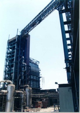
I am attaching a foto of the industrial instalation , rated at 200 tons per hr.
due to plant trafic the pipeline had to rise immediately to 54 mts , cross the patio and then rise to 84 mts to the roof of the building. ■
Finally Photo
this a view of the industrial instalation you can notice the almost immediate rise . the plant has been working for abouth 10 years now.
you can find more pictures in the HYLSA site under HYTEMP or in the cd released a¡in the second HYtemp meeting in monterrey.
Also in the document presented by Alberto Soriano at the ADIAT industrial innovation price 2000 published in their site , the project won the national ADIAT industrial innovation Price.
Here you can find a detailed layout and more pictures. a list of the PHD tesis and the patents produced.
Attachments
■
Re: Pneumatic Conveyor Pipeline Sizing
By the wy i might be able to get a copy of the paper to a few of you guys but the document is in spanish , and is abouth 7 megas.
send me an e.mail and I wil,send it trough my Gmail account .
marco
the same goes fior the IFPS pper . this one is in english.
marco ■
Re: Pneumatic Conveyor Pipeline Sizing
You are more then well come to contradict everyone. It is always nice to hear contradicting statements. As far as the changing the long radius bend to short radius, it sounds like the bigger 3” particles were getting smashed into smaller particles thus no blockages. If you provide PSD analysis before and after conveying we can discuss this further. If the paper on this system is in English it would be interesting in reading it. Unfortunately I don’t understand Spanish so your paper wont be much use to me. ■
Re: Pneumatic Conveyor Pipeline Sizing
The IFPS (International freight pipeline society) paper is in english, due to this paper the society descided to honor me (as representative of my team) board member.
degradation was a mayor issue as the sponge iron is fragile and abrasive , so we had to keep the particle velocity as low as possible , that was also another reason to rise as soon as possible , we run 3 years of degradation test doing abouth 20 cold runs a day and abouth 2 hot runs a day with 2, 18 metric ton batches , Jorge Klinzing , Roy Marcus and Paul Solt helped with this endeavour , in fact we did made an IFPS meeting in Monterrey Mexico and the asistants were able to visit the industrial plant in the first stage of operation. Some of the visitors were prof Senz , F Rizk. Of course Paul Solt and some other from germany and japan whose names I do not rememeber.
Sorry that you could not read spanish.
The Association of Researc and Development Directives (ADIAT ) in spanish distinguished this project with the national industrial innovation price.
From here we went to help design and build de HISMELT plant in Australia. another large hot pneumatic conveying instalation.
Where we also used Tee Bends.
Once you use then you will love them . ■
Re: Pneumatic Conveyor Pipeline Sizing
BY the way Alberto Soriano came with something like an acumulated energy impact index to better define the pipeline expansions.
The statisticall analysis (degradation wise) was led by Prof vera from the TEC of monterrey and coordinated by Prof Gilberto Guzman , both now decesased and who we ow more than just words.
Juan Celada the third was one of the project champions within the board of stockholders and he more than anyone is responsible for the succes of the project.
Let me look for the papers and I will attach some of the results .(this was long ago)
You see this company is in bussiness for the money but they also know how to have fun .
The priject saved 6,000,000 dollars a year in gas , when the gas was 2 US per GCAL ,
plus reduced significantly the melting time in th electric furnace , here the data I remember was somewhere arrownd 20%
so the stock holders once they saw the system running to the first furnace descided to build a dedicated furnace for hot sponge iron, I believe it was a danielly furnace . an large investment in itself. the pneumatic transport system included the heater and compressor was abouth 6 millon dollars . ■
Pneumatic Conveying
Hi guys
Thank you all for such a great response. I never expected all the info. We have re-positioned our system to allow about 1m of straight before the bend, (best we can get ).On a similar system we have about 500mm straight then a 90 degree bend in the horizontal, then a 90 degree bend in the vertical and this works fine. I have arranged for a New Zealand company ( who contacted me via this forum) to give us a hand.
Thanks again
Cheers
Don ■

Pneumatic conveyor pipeline sizing
I am currently designing a system to pneumatically transport Sodium Sulphate from a silo via a rotary valve to another storage vessel. Approx 9 tph.
Is there a specific length of straight pipe ( ie 10x dia?) that I should have after the rotary valve and before the first 90 degree bend. We have space constraints which means we are planning to go straight from the rotary valve to a 90 degree bend, going vertical. I am using a 100mm dia stainless steel pipe with 1000mm radius bend. (10x dia, rad).
I would appreciate any advice you can offer. ■