

Conveying Of Cement
Dear Mr. Tuinenburg,
You are right with your statements concerning importance of temperature and heat transfer in pneumatic conveying lines.
But it is not a common (or realistic) example to convey approx. 400 t/h of cement with about 4.54 kg/s of air. This leads to an air velocity of about 21,5 m/s at the end of a 500 mm pipe! I have never seen such nig installation in cement industry (and I have seen a lot of installations during the last 35 years).
So please, slow down to 40 t/h (much more realistic and even the same physic, but with smaller nimbers, of course!).
Best regards
Klaus Schneider ■
Re: Pneumatic Conveying Is Temperature Driven
Dear Klaus,
I appreciate your interest in my posts.
And your comments do keep me sharp.
The given example of temperatures and heat transfer values are based on a calculation, which I made a some time ago, when I was investigating the energy balance in pneumatic conveying and how the physical phenomena of this heat transfer were.
I do not have that calculation in my files (or I cannot find them anymore)
Therefore, I re-calculated a cement conveying system that corresponded (more or less) with the example.
The Solid Loading Ratio in the example is 111.1/4.54 = 24.47
Based on this SLR, I found a possible conveying length of approx. 450m
Calculating the following installation:
400 m horizontal length
50 m vertical length
10 bends
Air supply piping: 15m - 5 bends – 400mm
For 400 tons/hr and this calculated SLR, a conveying air flow of 4.58 kg/sec is determined.
For an end velocity of approx. 20 m/sec a 20” (Internal diameter 489 mm) pipeline is required.
Compressor: 4.58 kg/sec
Pressure: 2.5 bar
Calculation result:
455 tons/hr at 2.5 bar
Conveying power = 514 kW (which corresponds nicely with the calculated isothermal expansion energy of 524 kW in the example)
The calculated end velocity is 22 m/sec in a 20” pipe (Internal diameter 489 mm)
(As you also have calculated)
In the early 1990’s, I was the project manager of a cement unloader with a design capacity of 800 tons/hr in London.
The discharge installation existed of 2 conveying lines of 16” diameter.
Conveying length was:
horizontal = 455 m
vertical = 35 m
9 bends
Conveying air:
compressor 1.4 m3/sec + booster 2.1 m3/sec = 3.5 m3/sec
We achieved approx. 320 tons/hr for each pipeline.
I agree that there are not many installations that big, but they do exist.
In cement import terminals, distances up to 400 m (and a few over 400 m) are quite common, although the capacities are mostly limited to approx. 600 tons/hr over 2 pipelines.
Also Self Discharging Cement Carriers do have those big installations on board.
Also have a look at the thread:
https://forum.bulk-online.com/showth...loader-Vietnam
Calculating a smaller installation should generate smaller numbers of course, however, if I have my theories right, the same conclusion would emerge.
I believe that the internal gas energy, conveying energy, temperature and heat transfer theory is even more important in the application of venturi-eductors.
At low SLR’s, the material is relatively a low energy (heat) source, compared to the heat content of the gas.
Expansion and cooling of the gas has then a stronger effect.
Again, I appreciate and enjoy in depth technical discussions.
Have a nice day
Teus ■
Teus
Pneumatic Conveying Is Temperature Driven
Please allow me with REGARDS to the Gentlemen who are sharing valuable information. I think ,this forum is a Running institution.
Anil ■
Re: Pneumatic Conveying Is Temperature Driven
Dear Mr. Tuinenburg
In my opinion your heat balance is incomplete you need to take into account the heat losses from the pipe walls. Since very few conveying systems are insulated so heat loss from the pipe walls cannot be ignored. Once you add these figures you will find that heat losses only in the clean section of the pipe will be very substantial and will change the whole equation. In a dense phase system where the powder is close to ambient temperature the mixture temp will be almost same as the solids temperature within 2-4 m of the conveying pipe. This is due to very high surface area of the powder which makes it a perfect mixing system. Since the Cp of solid is much higher than air the temperature increase of solid will be minimal. After further 15 -20 m it will probably reach ambient. This is mainly due to heat losses form the pipe wall. Simple test is if you touch a pipe at the screw compressor then it is about 120 -170 C approx depending on the conveying pressure. But if you touch a pipe after 20m it is hot but you can touch it and if you touch at the screw pump it is just warm.
Other things which need attention in this situation are air volume change due to sudden cooling of air to the bulk solid temperature. Transfer of energy from air to solid particles, frictional losses. All these factor are important and have significant effect in heat balance.
Your conveying figures as ever are very typical of Screw pumps where you need 16” pipe for 400 tph. If you use dense phase vessels and convey at 4 -4.5 barg then these rates at this distances can be achieved in 12” stepped to 14” and substantially lower air flows.
Last but not least the Tilbury unloader you have mentioned according to my information it only achieved 50% of the design rate and that was after a lot of tinkering with it. Maybe you can enlighten us further with the problems with the unloader one day.
Have a nice day. ■
Re: Pneumatic Conveying Is Temperature Driven
Dear Mr Mantoo,
I am very pleased with the attention with which you have read my thread and with your in depth remarks.
You are correct that the heat balance in the example is not clearly completely presented, although I mentioned :
If the material is very cold, then the mixture temperature can become lower than the surrounding’s temperature and then the pipe wall transfers heat from the surroundings to the conveying mixture.
(The conveying pipe acts as a heat exchanger)
The main objective was to indicate that heat transfer is driving the physics of pneumatic conveying.
In my computer program, I calculate at every 0.001 sec the heat exchange between the compressed gas and the conveyed material, the cooling effect of the expanding gas, the heat exchange with the surroundings (pipe wall) and the generated heat of product friction, which flows back into the gas.
Your description of the rapid temperature drop from the gas at the mixing location and subsequently in the first 15m to 20 m further in the pipe is also in line with my field experience.
As I have been a designer/project manager in big grain unloaders, big cement unloaders and cement (and other powdery products) conveying installations, the calculated examples are indeed mostly based on the usual parameters for these installations.
Normally, the chosen conveying pressure is/was approx. 2.5 – 3 bar, which made oil free screw compressors with internal compression applicable.
You are correct, that in high pressure installations of 4.0 – 4.5 bar smaller pipe diameters can be used for the same capacity.
Due to the higher SLR, the total heat capacity of the material is more dominant in relation to the gas heat content.
In addition, for the higher pressures, normally oil filled compressors with coolers are used, resulting in lower gas temperatures at the mixing point.
Stepped pipelines are more beneficial at these pressures, although in the offshore industry, where these pressures are applied, single diameters pipe lines are applied.
About the Tilbury unloader:
Design capacity was 800 tons/hr.
1 suction pipe
1 suction product/air separator filter kettle
2x double tank pressure system, blowing into 2 16” pipelines over approx. 500m
After delivery, a performance test was executed.
Maximum suction capacity: approx. 700 tons/hr at 0.68 bar vacuum
Maximum discharge of pressure side; approx. 2x 340 tons/hr = 680 tons/hr at 2.5 bar
Average unloading capacity of complete unloader (suction and discharge combined) was approx. 360 tons/hr. (Tested on a 6000 dwt ship, although the design was for a 35000 dwt ship)
The unloader was accepted after the performance test. (April 1991)
Later on, the unit was used to unload alumina, which worked after using all possibilities in the design, such as combing the 2 by-pass regulators on 1 of the 2 systems.
The 400 tons/hr, mentioned by you is possibly the through the ship capacity. (compared to the measured 360 tons/hr in the performance test.
After March 1994, I lost contact with the ins and outs of the unloader.
This discussion about the physics of pneumatic conveying is showing that calculations are rather complicated and up till now, I did not found a calculation method that includes the temperature balance nor the actual product velocity calculation and the influence of the suspension velocity on the energy required to keep the material in suspension any way.
Have a nice day too
Teus ■
Teus
Estemation Values
 Originally Posted by Mantoo
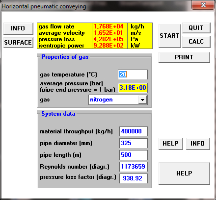
href="showthread.php?p=78142#post78142" rel="nofollow">
Hi! I would like to show you the calculation results of my software for the design that you have described. The conveying conditions lie on the dense phase boundary. Best regards
href="https://forum.bulk-online.com/attachment.php?attachmentid=35640&d=1363347564" id="attachment35640" rel="Lightbox78203" target="blank">■
Re: Pneumatic Conveying Is Temperature Driven
Dear Mr ManfredH,
The actual design, you refer to, does not really match the calculation, you made.
The real design has a 16”pipeline (diameter=397 mm) where you use a pipe diameter of 325 mm
The real designed airflow is a compressor of 4800 m3/hr plus a booster of 8400 m3/hr, totaling 13200 m3/hr, equaling approx. 15576 kg/sec AIR mass flow. (Not mentioned in the previous replies)
In the screenshot, I read 17680 kg NITROGEN mass flow, equaling approx. 14983 m3/hr.
You calculate 400 tons/hr at a pressure drop of 4.282 bar, while in the real installation a capacity of 340 tons/hr is reached at a pressure drop of approx. 2.5 bar.
The calculated average gas velocities (actual installation and your calculation) are almost equal.
The gas flows, diameters and average pressures differ in such a way that the calculated results are close. (this must be regarded as a coincidence)
It would be interesting to know the recalculated result according the really built installation. for ordinary cement.
Have a nice day ■
Teus
Re: Pneumatic Conveying Is Temperature Driven
Originally Posted by Teus Tuinenburg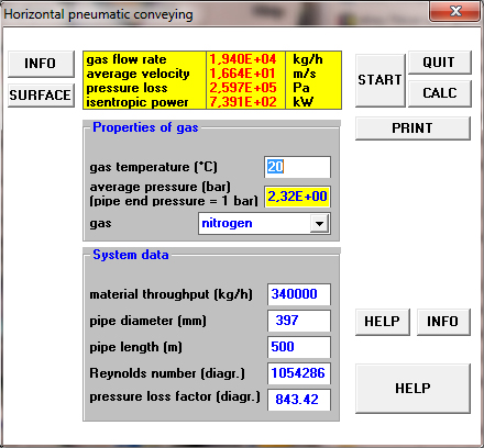
href="showthread.php?p=78307#post78307" rel="nofollow">
Dear Mr. Tuinenburg! My calculation was oriented to the data for a pipe diameter of 12"/14" given by Mantoo. The pressure loss of about 4.5 bar was confirmed. For the airflow was no comparison possible.
The attached screenshot shows the calculation results based on your data. The pressure loss lies at 2,5 bar. The airflow of around 19000 kg/h is about 20 percent too high. The reason for this discrepance may be, that the material throughput of 500 kg/h means a substantial extrapolation of my current state diagram.
Calculation results in comparison to really built installations for cement are discussed based on the data sets, I extracted from several bulk-online threads (see the list in my downloadable publications). The maximum cement capacity was 120 t/h.
Best regards, Manfred Heyde
href="https://forum.bulk-online.com/attachment.php?attachmentid=35725&d=1364208245" id="attachment35725" rel="Lightbox78321" target="blank">■
Re: Pneumatic Conveying Is Temperature Driven
Dear Mr. Manfred Heyne,
I understand that the previous screenshot was referring to Mr. Mantoo’s high pressure installation proposal, instead of referring to the really built installation.
I recalculated the “built” installation for a 20% higher airflow, but that increased the capacity only by approx. 4%.
This is caused by the fact that the design is close to the lowest point in the Zenz diagram, where the pressure does not change much at a varying airflow.
Tanks for the info
Have a Nice day
Teus ■
Teus

Pneumatic Conveying is Temperature Driven
Energy transfer and changes between gas, material and surroundings during compression and pneumatic conveying
Pressure discharging:
During compression of the gas, external energy (compression energy) is converted into internal energy of the gas.
This internal energy of the gas is expressed by the compression temperature (kinetic energy of the gas molecules).
The reached temperature is depending on the compression method.
Adiabatic: Without heat exchange with the surroundings
Isochoric: By heat exchange with the surroundings (constant volume)
Isothermal: Heat exchange equals the external compression energy. (constant temperature)
When the conveying air is mixed with the conveyed material, there is heat exchange to a mean mixture temperature at the (constant) pressure of the mixing zone.
As the heat content of the material is generally high, compared to the heat content of the conveying gas (SLR >> 10), the mixture temperature is close to the material temperature.
During the pneumatic conveying, the gas expands at cost of the internal energy, resulting in a lower temperature.
The internal gas energy (temperature) is used to convey the material and cover the energy losses for particle collisions, air friction and the energies, required for acceleration, elevation and keeping the particles in suspension.
If this lower temperature (meaning lower internal energy left) is not compensated, the pneumatic conveying would result in very cold gas and subsequently in much lower gas velocities than required.
However, when the gas expansion results in lower gas temperatures, the temperature of the material becomes higher than the temperature of the gas.
The higher material temperature forces heat to flow to the gas and the gas is reheated.
As the heat content of the material is generally high, compared to the heat content of the conveying gas (SLR >> 10), the mixture temperature stays close to the material temperature.
The tendency is that the expansion during conveying is approx. isothermal.
The isothermal expansion of the conveying gas in pressure conveying, where the external energy equals the internal energy, is made possible by the material and surroundings as a heat source.
If the material is very cold, then the mixture temperature can become lower than the surrounding’s temperature and then the pipe wall transfers heat from the surroundings to the conveying mixture.
(The conveying pipe acts as a heat exchanger)
In pressure conveying, cooling the compressor air before mixing with the material has normally no significant influence on the conveying performance, as the mixture temperature is always close to the material temperature.
Vacuum conveying:
In vacuum conveying, the starting temperature is normally the ambient temperature.
The mixture temperature is, due to the high heat content of the material, compared to the heat content of the gas, close to the material temperature.
The lower temperatures from the gas expansion are in vacuum conveying, as well as in pressure conveying, compensated by the heat content of the material and the heat exchange with the surroundings.
The isothermal expansion of the conveying gas in vacuum conveying, where the external energy equals the internal energy, is made possible by the material and surroundings as a heat source.
Example of material heat transferred into internal energy of gas:
Mass-air = 4.54 kg/sec
T1 = 150 +273 = 423 K (Air temperature after compressor)
T2 = 54,7 +273 = 327.7 K (mixture temperature)
cp = 1.005 kJ/kg.K
Mass-cement = 111.1 kg/sec
T1 = 50 +273 = 323 K (Cement temperature)
T2 = 54,7 +273 = 327.7 K (mixture temperature)
c-cement = 0.8372 kJ/kg.K
Transferred heat into internal energy:
E-transf-air internal = cp * Mass-air * (T1 – T2) = 1.005 * 4.54 * (423 – 327.7) = 434.8 kW
E-transf-cement internal = c-cement * Mass-cement * (T2– T1) = 111.1 * 4.54 * (327.7– 323)= 437 kW
Example for estimating the available internal energy for conveying as a result of the expansion mode:
Mass-air = 4.54 kg/sec
p1 = 2.5 + 1 = 3.5 bar(a)
p2 = 1 bar(a)
T1= T2 = 54,7 +273 = 327.7 K (mixture temperature)
cv = 0.716 kJ/kg.K
k = 1.4
R = 287.14 J/kg.K
Internal energy change at isothermal expansion:
Einternal isothermal = Massair * R * T * ln(p2/p1) = 4.54 * 287.14 * 327.7 * ln(3.5/1) = 524.6 kW
Internal energy change at adiabatic expansion:
T2 = (p2/p1)^((k-1)/k) * T1 =(1/3.5)^((1.4-1)/1.4) * 327.7 = 229.1 K # 229.1-273 = -43.9 C
E-internal adiabatic = Mass-air * cv * (T1 – T2) = 4.54 *0.716 * (327.7 – 229.1) = 320 kW
Resume:
-As the internal energy of the conveying gas (the available energy for pneumatic conveying) is solely determined by the temperature of the gas, the heat transfer between the conveyed material and surroundings and the conveying gas is very important (heat balance).
-Cooling the conveying gas before entering the pneumatic conveying system reduces the internal energy of the gas. However, the internal energy of the gas is restored by the heat from the conveyed material and by the surroundings as long as the ambient temperature along the pipe route is higher than the mixture temperature.
-Heat loss along the conveying pipe reduces the available internal energy for pneumatic conveying. Insulation of the pipe where the mixture temperature is higher than the ambient temperature is then beneficial. (Prevention of heat loss). Where the mixture temperature is lower than the ambient temperature, a pipe without insulation is beneficial (internal energy is increased by heating from surroundings)
-The pressure of the conveying gas determines the exponent of expansion and thereby the rate of converting internal energy into other forms of energy in combination with heat transfer from the material and the surroundings.
-Heat transfer- and temperature calculations have to be a part of the complete pneumatic conveying calculation.
Conclusion:
A pneumatic conveying calculation has to account for the influence of heat transfer between gas and material and surroundings on the gas temperature, as the internal energy, available for conveying, is the only energy source.
Statement: Pneumatic conveying is temperature driven and the temperature heat balance cannot be neglected. ■
Teus