

Re: Pneumatic Conveyance Layout Project
Dear Dana,
Need some more info:
1.Pressure conveying type system
OK
2. Screw feed device to pneumatic transfer pipe
OK
3. Partial size 500 to 1 micron (average 300 micron)
?Particle size plastic?
?Particle size limestone?
4. Partial density 5lbs/FT^3 (80kg/m^3) plastic, 50lb.ft^3 (800kg/m^3) limestone dust
Particle density plastic = 80kg/m^3
Particle density limestone dust =800kg/m^3
?Or are these figures bulk density?
5. Bulk density 37lb./ft^3 (600kg/m^3)
Bulk density plastic = ?? kg/m^3
Bulk density limestone dust =???kg/m^3
6. 500 (150m) feet above sea level
OK
7. Material feed rate 17tons/hr. (15425kg/hr.)
OK
8. Pipe layout-24” (.609m) down then 130” (3.3m) up with three 125 degree 90” radius bends 100’ (31m) total length.
More accurate geometric description?
9. Standard atmospheric conditions and 35deg. C
OK
10. 1 week test not concerned for wear in equipment
Are you planning to build a test installation or is there already an installation?
11. Assume roots type blower?
If you require the application of a roots type blower, the system can be designed for the allowable pressure.
What size pipe and CFM and conveying pressure do you recommend for this application? I would like to try and keep the CFM low and still achieve very constant flow.
The constant flow is taken care of by the screwfeeder.
Best regards
Teus ■
Teus
Re: Pneumatic Conveyance Layout Project
Dear Teus,
Here are my responses to your questions. Thank you for your time!
3. Particle size plastic is 500 microns minus and under, average is about 300 microns
Particle size lime stone is 150 microns minus average about 75microns.
4. Sorry bulk density
5. Bulk density of the mixture of constituents.
8. The pipe comes out from the metering system and travels down .609 meters in elevation and forward 4meters, then it bends 112 degrees horizontal at a 2.2meter radius to a 10 meter long section then to a 130 degree horizontal bend at 2.2m radius to a 5.08 meter straight section, then it bends upwards at a 145 degree bend at 2.2m radius for 5 meter straight section. I attached a cad view of the layout I hope it helps understand. Its fairly unrestricted i tried to make the bends as long as possible.
10. We are building the system so nothing is completed.
11. I would like to keep the line size smaller and I assumed using the roots blower with a higher pressure would allow that?
Thank you,
Dana
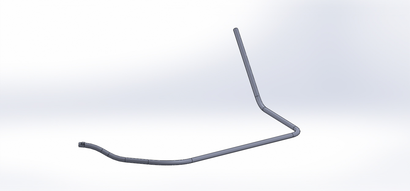
href="https://forum.bulk-online.com/attachment.php?attachmentid=36542&d=1371477438" id="attachment36542" rel="Lightbox79511" target="blank">■
Re: Pneumatic Conveyance Layout Project
Dear Dana,
From your info, I understand that you want to convey a mixture of plastic and limestone.
As these are 2 different materials with different particle size and density, I estimated a virtual particle with a weighed particle size and density that represent pneumatic conveying properties of the combination of the two.
From the given densities, the weight ratio of the plastic is 27.8% and the weight ratio of the limestone is 72.2%
The virtual particle has then a particle density of 1875 kg/m3 and a particle size of 90 micron, resulting in a suspension velocity of 1.82 m/sec.
The I modeled the pipeline and calculated 3 installation with a positive displacement blower as compressor. (Maximum pressure = 1.0 bar)
Calculation results:
3” pipeline:
compressor = 0.07 m3/sec
capacity 9.35 tons/hr at 1.0 bar
SLR = 32.8
Begin air velocity = 8.1 m/sec
End air velocity = 19.7 m/sec
4” pipeline:
compressor = 0.1 m3/sec
capacity 14.9 tons/hr at 1.0 bar
SLR = 34.7
Begin air velocity = 7.1 m/sec
End air velocity = 17.8 m/sec
5” pipeline:
compressor = 0.16 m3/sec
capacity 22.4 tons/hr at 1.0 bar
SLR = 34.6
Begin air velocity = 6.8 m/sec
End air velocity = 17.3 m/sec
5” pipeline:
compressor = 0.16 m3/sec
capacity 17.0 tons/hr at 0.6 bar
SLR = 26.7
Begin air velocity = 8.7 m/sec
End air velocity = 15.1 m/sec
Note:
There are no known pneumatic conveying properties for a plastic/limestone mixture and therefore I assumed an weight interpolated solid loss factor.
I noticed that you have used very long radius bends (28D to 17D). I am not sure whether this is a good idea. Such a long bend looks more to a series of bends.
Please note the above calculations as an indication, due to the significant uncertainties.
Is a preliminary test with a bulk truck an option?
Take care
Teus ■
Teus
Re: Pneumatic Conveyance Layout Project
Teus,
Thank you for your work I greatly appreciate it.
Dana ■
Re: Pneumatic Conveyance Layout Project
Dana,
You are welcome.
Take care
Teus ■
Teus

Pneumatic Conveyance Layout Project
System parameters
1.Pressure conveying type system
2.Screw feed device to pneumatic transfer pipe
3.Partial size 500 to 1 micron (average 300 micron)
4.Partial density 5lbs/FT^3 (80kg/m^3) plastic, 50lb.ft^3 (800kg/m^3) limestone dust
5.Bulk density 37lb./ft^3 (600kg/m^3)
6.500 (150m) feet above sea level
7.Material feed rate 17tons/hr. (15425kg/hr.)
8.Pipe layout-24” (.609m) down then 130” (3.3m) up with three 125 degree 90” radius bends 100’ (31m) total length.
9.Standard atmospheric conditions and 35deg. C
10.1 week test not concerned for wear in equipment
11.Assume roots type blower?
What size pipe and CFM and conveying pressure do you recommend for this application? I would like to try and keep the CFM low and still achieve very constant flow.
Best Regards,
Dana ■