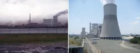
Lignite from the Maritza basin has always played a key role in Bulgaria’s energy supply balance. The three major power stations Maritza East 1, 2, and 3 deliver around 40% of the overall energy production of Bulgaria. Since 2006, the new owner AES has been replacing one of these three power stations – Maritza East 1 – with a new build comprising two blocks with a power output of 300 MW each.

1. Residue Disposal at ‘Maritza East 1’
The process of generating electricity from lignite produces significant amounts of residual products, which need to be either disposed of or put to other continued use. Pulverized fuel ash and gypsum can be reused in the construction materials industry, while bottom ash is usually dumped in landfill sites. Due to the lack of any subsequent infrastructure on the side of the construction materials industry, owner AES decided to permanently deposit all of the arising residual products at the dumping ground of a former open-cast mine situated around 9 km away from the power station.
In the old power station, the ash was put into interim storage in a sluicing dump before subsequently being transported by rail to the site of the dumping ground. As part of the plans for redeveloping the power station, the issue of residual product disposal was also examined and re-evaluated. In the process, the existing practice involving railway transportation was eliminated in advance from further considerations, as was the possibility of transporting the materials via truck, as this would have involved driving through a village and almost half of the route would have been on public roads.
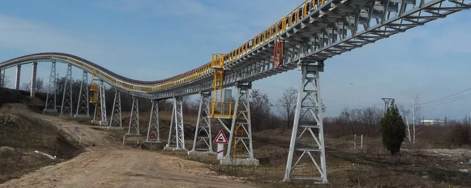
As a conventional conveyor belt transport system was found to be non-viable on account of the complexity of the route along the former railway line, the decision was taken at a relatively early stage to use a tube conveyor. Three possible variants were considered for the long-distance transportation from the power station to the landfill site:
- A 4.5 km long tube conveyor combined with a truck loading station at the end of the conveyor line and transportation via truck for the final 4 km, with an option for upgrading the second part at a later date and adding a second tube conveyor with a length of 4.3 km. This variant requires the lowest initial investment. It is slightly more flexible than the other two variants. Since a fleet of 24-t trucks needs to be available anyway for the second part of the transport chain, this means that a back-up is already in place that allows at least some of the waste products to be disposed of from the power station by truck if the conveyor fails.
- Single 8.8 km tube conveyor with intermediate storage facility at the end of the conveyor line. In terms of technology, this variant is the most reliable. The material is transported in a single stage right up to the landfill site area, where it is dumped on two transfer heaps. From here, the material is distributed with wheel loaders or trucks to the final landfill destination and dumped. However, there is no back-up in the event of failure of the conveyor system, as only a small number of trucks is kept available for use on the landfill site.
- One conveyor line with an overall length of 8.8 km, comprising two tube conveyors measuring 4.5 km and 4.3 km in length, respectively, with an intermediate storage facility at the end of the second section of the conveyor. Transportation from the unloading point of the second tube conveyor to the dumping site is performed similarly to the setup for variant 2 with a small fleet of trucks or wheel loaders. As mentioned before, in the event of the conveyor system failing, there is no possibility for performing the complete transportation of residual products with the aid of trucks.

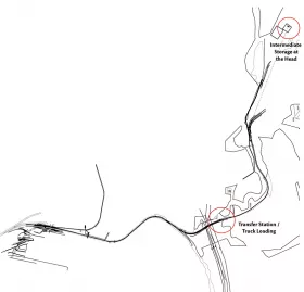
On the basis of the available financial framework, the power station operator opted for the first variant, which does not involve truck-based transportation on public roads here. This solution represents the best compromise for the customer in terms of the funds available for investment, environmental requirements and the operational safety and reliability of the plant. The option for extending the conveyor line to 8.8 km at a later date has also been incorporated in the plans (Fig. 2).
After a tendering process that took around a year and enabled AES to arrive at a final decision, the order for the design, construction, supply, assembly, and commissioning of the entire residual product disposal system was awarded to Takraf in August 2007.
According to the specification, the mixture of materials being conveyed is made up of 48% pulverized fuel ash, 45% gypsum and 7% bottom ash, whereby both the moisture content and density of the materials can vary. In addition to a mixture of the three materials, it must also be possible for each material to be conveyed individually. This made it very difficult to predict how the material would behave during transport. In addition, previous experience showed that, depending on the mode of operation of the power station and silo installations, the actual demands placed on the system during day-to-day operation can differ greatly from the specifications defined beforehand, so it was important that the transportation system should be able to cope with any such deviations.


