

Handling Wood Chips
I think that it is right to point out that specialised manufacturers employ techniques for handling difficult materials based on hard won experience, so it is not practical to share this intellectual property with essential competitors or those who chose to go their own route. With a 200 mm diameter screw in a 220 mm diameter casing it seems unlikely that wood chips 20 x 20 x 60 mm would remain between the screw and the casing over the whole travel. However, it also seems likely that the chips are of variable size and irregular shapes, so will probably jam in the clearance between the flight tips and the casing, as is indicated by the bad practice of reversing the screw to free a blockage, even by a small amount, when filled with product. Apart from the prospect of damaging the inlet end flight by compaction, this radically reduces the transfer capacity of the machine.
I would say that elevating direct for a hopper at 65 degrees is not easy, both to secure adequate flow at the interface between the hopper and screw and to provide an efficient elevating mechanism. Wood chips do not flow easily, so it is no small challenge to design a flow channel that will reliably transfer the chips from a hopper into a screw against the resistance offered by a steeply inclined, rotating screw. In addition, a screw will not elevate by gravity mode at this inclination, so must work in either flood or dynamic mode to lift the material. The various mechanics of these forms of conveying are described in more detail in my book – ‘Guide to the design, specification and application of screw feeders’ published by The British Materials Handling Board. However, in both methods that maybe employed, it is not practical to minimise the danger of particle trapping by techniques that are available in gravity mode conveying, so the flight tip clearance must be selected to suit either a minimum clearance, if no slivers are present, or one that is sufficiently large to avoid ‘lamination blockage’. The mechanics of flood mode is effective at any rotational speed and is similar to the operation of a horizontal feeder, depending on casing friction to restrain product rotation and drive the product round an inclined helix. The difference is that discharge will cease short after the in-feed stops, leaving the machine virtually full of product that will not clear and may cause re-starting problems. At higher rotational speed the material in transit experiences a centrifugal frictional resistance from the casing and will clear a higher proportion of the machines contents. Employing a square casing eliminates any chance of the clearance layer rotating to elevate and ensures a rough boundary layer against which the screw contents must shear, so is to be avoided.
Trial and error without experience can be expensive in time and effort, so you may well be advised to contact a company that specialises in screw type equipment to sort out your problems. ■
The Same Problem Over Here
hi forum members,
over here the same problem appears. It looks like the woody biomass, has an resilient property. The smaller chucks can be forced into the gap between the
screw tip and the pipe. The biomass is the jamming the screw, with a overheated engine as result because the power required for turning the screw forward is x10 bigger.
My company also have this problem, and we are looking for a new kind of screw. we handle woodblocks (40x20x50mm) relative hard wood, so low resilient property.
the angle of the screw is +- 45 degrees,
the screw has to be airtight: a rotaryvalve is placed to feed the screw
The engine has to be set, dependent on which type of screw.
The feeding speed is super low: we need about 0.2 m a hour.
(is it possible to turn the screw one rpm a hour?. batch loading is applied so the engine has to be off 90% of the time, otherwise it is a waste of energie)
Our question, which type of screw can be used? we studied literature, those literature say that when applying material above 2``, the screw diameter should be 18`` (to big for our application!)
Hoping for some information.
kind regards wessel ■
Biomass Burner
 Originally Posted by wessel574
++++++++++++++++++++++++++++++++++++++++++++++++++++++++++++++++++++++++++++++++++++++++++++++++++++ ++++++++++++++++++++++++++++++++++++++++++++++++++++++++++++++++++++++++++++++++++++++++++++++++++++ ++++++++++++++++++++++++++++++
Well you have come to screaching halt at the left hand fork
of the roadblock.
What your missing is the basics. It takes adhesion, weight,
traction and mass to move any given mass.
Please examine how a concrete pumper works, it recieves the
wet concrete from a ready mix truck and it uses a pair of
hydraulic rams rams drive the concrete into the concrete pipeline
to the end of the crane boom and into the flexible hose used to
drop and place the concrete mix in a form for a foundation pour.
The easy way to do this is uses a worm gear attached to the interior
of the rectangular pusher to force the biomass into the burner using
a simple 110 volt timer and bidirectional 110 volt electric motor with
a reduction gearbox to rotate the screw with the following;
A garage door opener with a screw drive will work fine for you.
The sealed rectangular box within the trough feeding the burner is
forever sealed against any bomass entering behind the screw which is
within the interior of the sealed box with an end bearing and locking collar
for lubrication of the screw end bearing. NO you do not want the bearing
on the interior side because you will forget to grease it!!!!!!!!!!!!!!!!!!!!!!!!!!!!!!!!!!!!!
The stroke is limited by the length of the screw which also protects the
bearing from the heat of combustion as the end of the pusher box does
not get close enough to the burner to affect the bearing.
The stroke in the forward direction is stopped by a limit switch that is
positioned beneath the open bottom of the rectangular box which is
stopped and reversed by a stationary paddle target attached/welded within
the box interior on both ends of the plungers stroke to control forward and
reverse motion with a timer which uses a normally open limit switch to control
the direction of travel with a second limit switch on the retract function to
stop the pusher box on the return travel portion of the process.
you need an electrician to do the wiring with the timer and an automatic reversing
controller wired into the 2 limit switches exactly like a garage door functions only slower. ■
Re: Designing Screws For Wood Chips
A few basic features: -
- Lumps tend to form flow blockages, see 'Solid Sense' notes on hopper outlet requirements.
- large, hard, irregular shaped components tend to jam is working clearances, specialised design features can mitigate problem.
- Rotary valves do not like large, hard pieces because they tend to jam and block flow channels
- Screws do not work well at inclinations above 30 degrees, so specialist suppliers are recommended for steep inclinations.
- Screws will work at very low speeds, the travel time has to be allowed for when priming and running out.
The combination of elevation, awkward bulk material and very low feed rate presents some difficulty and any manufacturer should be wary of offering equipment for this duty without a close understanding of the site conditions and especially knowing the full range of bulk material conditions that have to be accommodated. ■
Biomass Screw
I would believe Lyn has an answer to your question. He is a specialist in these matters. You can hire him to design of do the ropa-dope with the many answers that abound here abouts.
I have an idea of how the screw should be forms, that Lyn can already tell you. I would have to model it in ROCKY the non-round particle Discrete Element Method (DEM) code. WE can configure biomass dimensions. I do not think it is difficult, only unusual. Try Lyn first.
I think you need to take two steps back to see the solution. The wall to screw is not a problem.
I a quite sure other biomass engineers have conquered it. ■
Difficulty Biomass Specs
@ lyn and nordell,
The difficulty to feed the biomass into a gasifier is indeed a problem, many biofuel engineers counter with.
it is also a no option to hire specialist, this is because i am doing a case study, there is no client yet.
a simulair plant is build in the us. they also use chips and corn cabs.
the have a small screw, with a heat exchange pipe around (the productgas of the gasifier heats up the biomass, this will increase the efficiency)
see more details:
href="http://gekgasifier.com/wpgallery/100kw-powertainer-at-apl-june-2012/nggallery/image/powertainerapl2-21-2/" target="blank">http://gekgasifier.com/wpgallery/100...inerapl2-21-2/
the use also a rotary valve to keep things airtight.
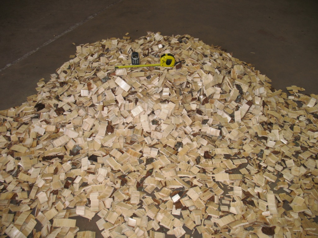
the angle of the screw can be decreased to 30 degrees. a picture and material specs :
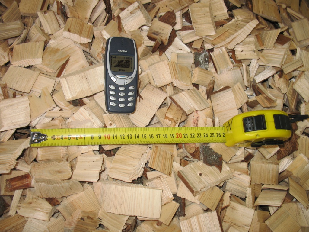
href="https://forum.bulk-online.com/attachment.php?attachmentid=33625&d=1343375682" id="attachment33625" rel="Lightbox75410" target="blank">■
Case Study For Biomass Feed
A case study without a solution to a key part must be difficult toput together. In this particular situation a solution is most likely to hand, it is just in a specialist field. It is not realistic to expect an expert to supply free help to dispense with his services, but is valid to enquire what the cost f a solution would be, even for a case study. ■
Lump Size Limitation
If you check the lump size limitation of the screw you will see that the minimum recommended screw diameter is over 12 inch, you have around 9. It is to our point of view logical that you face problem. On solution, if possible increase the screw diameter. Other wise filing level 15%. If you want the technical documentation for screw calculation please send me a mail. I will forward the data. www.archimedys.com
regards
S Osmani ■
Feeding Wood Chips
There is much more to avoiding jamming in a screw feeder than increasing the diameter of the screw. The design of a screw feeder involves an intigrated approach between the screw and the feed hopper, each of which require serious design attention. There are also various factors to take into acount when the matching of the feeder outlet with a reactor, particularly if delivering to a elevated temperature region and/or a hazardous gas area. I would suggest that this duty is no task for the inexperienced. For a case study it is adequate to size the hopper and envlope of the feed system, as these may be determined relatively easily. The devil is in the detail and it is no coincidence that many biomass systems fail because the feed arrangement does not work properly, if at all. ■

Designing Screws for Wood Chips
Dear sir:
We are designing a system to move biomass from a hopper to the inlet of a gasification reactor.
My first problem is that we need a very large slope (65º).
The main features are:
process:
flow 1.30m3/h
material:
wood chips
size: Around 60mmx20mmx20mm
Screw:
diameter:200mm
pitch:150mm in the inlet and the first part (1m) and 200mm for the rest of the screw.
inner diameter:60.3mm
Casing; 220x6mm tube
intermediate hangers: No
drive:
helical gear motor: 20rpm-1.1kw
We did the first tests and we can see that the chips introduce between the casing and the flights and probably stay there during the whole travel in the screw. For this reason the system sounds very bad and after some minutes the gear motor stops because it's very hot.
Also we think that the screw is rotating too slow and for this reason the screw is full of chips increasing the previous problem.
We solved partially this issue changing the way of working of the screw.NOw it works forward during 8-10seconds and works backward during 1-2 seconds. In this way the chips trapped are free and everythig improves a lot but after some hours the gearmotor is very hot and stops.
We think about some solutions for this:
1.-Use a square casing avoid the chips stay between the casing and the flights all the travel.
2.-Move the screw faster to avoid the screw working full of chips. In this point we don't know if use a higher rotational speed with the same power ( reducing the torque) or increase the the speed and keep the power.
I would like to know your opinion about this.
Thanks in advance ■