
(From the archive of ”bulk solids handling", article published in Vol. 33 (2013) No. 4 , ©2013 bulk-online.com)Overland tubular pipe conveyors can overcome difficult terrains and protect the environment. But a pipe conveyor’s power consumption typically doubles that of comparable trough conveyor, due to the additional rolling resistance from the pipe belt. For an overland pipe conveyor longer than 3 km, the capital and operating costs from the increased power consumption are significant. The Low Rolling Resistance (LRR ) trough belt is well studied in theory, tested in lab, and proven in conveyor applications. This article describes a methodology that analyses LRR pipe belts and introduces recent applications of LRR pipe belts on overland pipe conveyors that reduces power consumption and improves performance.
1. Introduction
Belt conveyors have been widely used as an efficient way to transport bulk materials. The ubiquitous trough belt conveyors have the benefit of a high degree of reliability and availability, and low operating and maintenance cost. However, trough belt conveyors have limited capability to negotiate difficult terrains, mainly due to the limited horizontal curves they can withstand. Typical curve radii are about thousands of meters. Tubular pipe conveyors solve this problem by folding the belt into a smaller pipe cross section, which allows the belt to rotate within idler frames. The allowable horizontal curve radii are about hundreds of meters. This conveniently falls within the range of the horizontal curve radii of a typical paved road. As a result, pipe conveyors can be constructed alongside existing roads. Being more versatile in conveyor routing also avoids some of the property rights and land permitting issues, which are becoming more important in an increasingly crowded world. The open trough belt could raise concerns about materials spillage into the environment. Folding the belt into the enclosed pipe shape separates the material from the environment. This protects both the material and the environment, especially for dusty materials with fine particles. In certain cases, this also protects the material from being stolen.Despite the benefits, pipe conveyors are more expensive than trough conveyors in terms of capital (excluding civil cost) and operating costs. The folded pipe belt, depending on its cross sectional belt stiffness, exerts additional contact pressure on idler rolls. The additional contact pressure, when coupled with the belt bottom cover, translates into additional indentation rolling resistance, belt tension, and power consumption. To accommodate the increased belt tension and power consumption, a bigger drive size and a more expensive belt are required, in addition to more idlers, which all increase the capital cost. The engineering of a pipe conveyor is more complex. The lack of open design standards limits the engineering proprietary to a few practitioners with good understanding and experience. Pipe conveyors with improper engineering, or a belt unfit for the system, can lead to problems that are difficult and costly to resolve.During recent years, more overland pipe conveyors longer than 3 km have been commissioned, with some conveyor lengths exceeding 6 km [1]. Now pipe conveyors longer than 10 km are being planned. As a general trend, it can be expected that the conveyor lengths will continue to increase, like overland trough conveyors, whose single-flight lengths have exceeded 20 km [2] and are now approaching 30 km. The higher friction, the increase in power requirement, and the belt tension that are intrinsic with longer pipe conveyors can quickly escalate to a very expensive level. Thus, making the long pipe conveyors more efficient has significant implications for system suppliers and end users.
2. Methodology
An overview of the LLR belt technology is given in Section 2.1. The extension of LRR belt technology to pipe conveyors is described in Section 2.2.
2.1 LLR Belt Technology
The components of energy loss in trough conveyors have been well studied. It is shown that the idler indentation rolling resistance can account for approx. 60 % of the total rolling resistance [3, 4]. Reducing the indentation rolling resistance is an effective way to reduce conveyor power consumption and the belt tension. The indentation rolling resistance is due to the hysteresis energy loss of the viscoelastic deformation in the belt bottom cover, which is closely related to belt bottom cover properties. The LRR belt has a modified bottom cover rubber with less hysteresis energy loss, compared to the conventional belt bottom cover rubber. Major global belt manufacturers now offer conveyor belts that have low indentation rolling resistance properties, for example, Goodyear’s Easyrider, Phoenix’ EOB (Energy Optimised Belt), and Bridgestone’s Energy Saving Belt.The question is how to quantify the low rolling resistance (LRR). It is an important question for conveyor design, component selection, and cost analysis. The indentation rolling resistance can be determined in a number of ways. Currently three methods are most commonly used: small scale rubber test, medium scale belt test, and full scale conveyor data acquisition. Small scale rubber test: The viscoelastic properties E’ (elastic modulus) and E” (loss modulus) of a small sample of the bottom cover rubber is measured over a range of temperatures, strains and frequencies using the Dynamic Mechanical Analysis (DMA) machine.The data acquired from DMA testing is post processed to generate master curves and is incorporated into mathematical models to calculate the indentation rolling resistance from the conveyor operating conditions. Conveyor Dynamics, Inc. (CDI), USA, has been developing its own proprietary small scale test methodology, applying it to conveyor design, and has been accumulating verification data since the 1990s [5].Median scale belt sample test: A full size, closed loop belt sample is installed on a 2-pulley test machine, where one pulley is driven and one pulley has variable position to regulate belt tension. The indentation rolling resistance over a range of temperatures, idler diameters, belt loads and belt speeds is measured by a single instrumented idler. University of Hannover, Germany and University of Newcastle, Australia independently developed such testing machines. Currently, one German standard exists (DIN 22123) on the median scale belt sample test. The equipment shown in Fig. 2 is the University of Newcastle’s belt test machine, where the belt sample and the instrumented idler are shown (by permission of Tunra Bulk Solids, University of Newcastle).
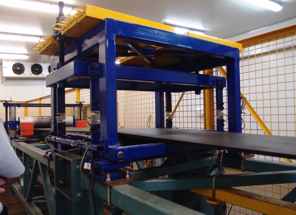
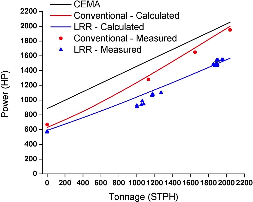
The indentation rolling resistance is expressed in force resistance of the test belt rolling over the instrumented idler, for the particular belt speed, load, idler diameter and temperature. Median scale belt sample tests have the benefit of testing an actual sample in a controlled lab environment. It can be used to compare different rubber grades from the same or different belt manufacturers to provide meaningful comparative indentation rolling resistance data. The test data can be incorporated into conveyor design tools to predict the power and tension of conveyors.Full scale conveyor data acquisition: the power consumption and belt tension of an operating conveyor are measured by strain gauges mounted on drive shafts. Other conveyor operating conditions, like belt speed, takeup tension, and material load, can also be measured by instrumentation. This method measures the performance of the actual conveyor system. As a diagnostic tool, the data collected can be used to trouble shoot existing problems, or used in engineering system upgrades. In terms of measuring belt rolling resistance, the conveyor data acquisition is especially insightful on the same conveyor with different types of belt.Conveyor Dynamics carried out data acquisition studies on a 7 km long overland conveyor in Ohio, United States between 1999 and 2000 [6]. The conveyor was running with a conventional conveyor belt and then replaced with LRR belt. For both belts, th company measured the bottom cover viscoelastic properties and compared with actual conveyor operating data. The result is summarised in Fig. 3. It is clear that:
- the LRR belt can produce significant power savings of more than 20 %, and
- the small scale rubber test, when coupled with a robust mathematical model, can produce accurate results.
2.2 LLR Pipe Conveyor Belts
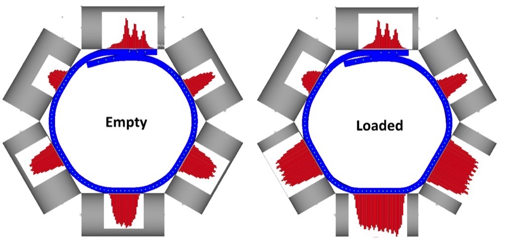
The main difference between pipe belt and trough belt is that the folded pipe belt adds additional contact pressure to idler rolls. The additional contact pressure increases the indentation rolling resistance, causing higher power consumption and belt tension for pipe conveyors. The magnitude of this contact pressure is not only related to the belt weight, material weight, and idler spacing, but to a greater extent, is affected by the cross sectional bending stiffness of the belt. For trough belt, the cross sectional stiffness can be measured by the troughability test (ISO 703:2007). High belt stiffness decreases troughability, which may cause the empty trough belt not touching the centre roll and belt tracking problem.The cross sectional stiffness can be modified by the belt construction: belt thickness, rubber modulus, and the fabric layer in top and bottom cover. By adjusting the type and spacing of the fabric layer, cover thickness, and even the rubber modulus, the pipe belt stiffness can be customized for individual applications.In general, a bigger diameter pipe requires higher stiffness to maintain full pipe shape, and a smaller diameter pipe requires lower stiffness. If the stiffness is too high, the pipe belt will have very high indentation rolling resistance. It can even cause the conveyor to be unable to start an empty belt. If the stiffness is too low, the pipe belt will collapse and will not be able to maintain the circular cross section. A collapsed pipe belt also tends to have large rotation and twist during horizontal and vertical curves. Belt tension also affects the belt stiffness design, where high tension would require higher stiffness, because during curves the bending force component is increased. To analyse all these factors, both experimental testing and finite element analysis (FEA) were developed [7]. The belt bending stiffness is measured by tests: 3 point bending test using a 300 mm × 50 mm belt sample, and 6 point pipe belt stiffness test using full width, folded pipe belt. The bending tests are also simulated in FEA, to establish a correlation with experimental results.After a proper belt construction is designed, the pipe belt FEA model is analysed for empty and fully loaded conditions. Fig. 4 shows the contact pressure of a 350 mm diameter ST1600 pipe belt, in empty and loaded conditions. The belt is constructed using the patented Goodyear Confine pipe belt design. It can be seen that the steel cord distribution is different from a conventional trough or pipe belt, where all steel cords have even spacing. The FEA outputs the contact pressure on idler rolls for empty and loaded conditions. The pipe belt shape and overlap opening can also be investigated. The contact pressure distribution from FEA is then incorporated into mathematic models to calculate the pipe belt’s indentation rolling resistance.
The mathematical models are modified from the ones used to calculate the indentation rolling resistance for trough belt, where the contact pressure distribution is different. The pipe conveyor model is capable of including the rubber viscoelastic properties, to calculate the power consumption and belt tension for different types of belt bottom cover. Now it is possible to study if a LRR pipe belt is used, what kind of power saving benefits, belt tension changes, and related conveyor system changes can be achieved.
3. Conveyors with LRR Belts
Low Rolling Resistance pipe belts have been implemented in several projects (Table 1). They serve as full scale tests to verify the aforementioned methodology.
| Project | Conveyor length [km] | Tonnage and material | Pipe belt |
| Itaqui | 4.3 | 1000 t/h, coal | Ø375 mm, ST1400, SLRR |
| Kailin | 6.2 | 850 t/h, fertilizer tailing | Ø375 mm, ST2500, LRR |
| Bulgaria Marista | 2.7 | 910 t/h, fly ash | Ø400 mm, ST1100, LRR |
| Yong Steel | 3.2 | 1000 t/h, iron ore pellets | Ø350 mm, ST2000, SLRR |
| CNOOC | 2.2 | 400 t/h, coke | Ø300 mm, ST800, LRR |
3.1 Brazil Itaqui Pipe Conveyors
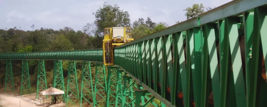
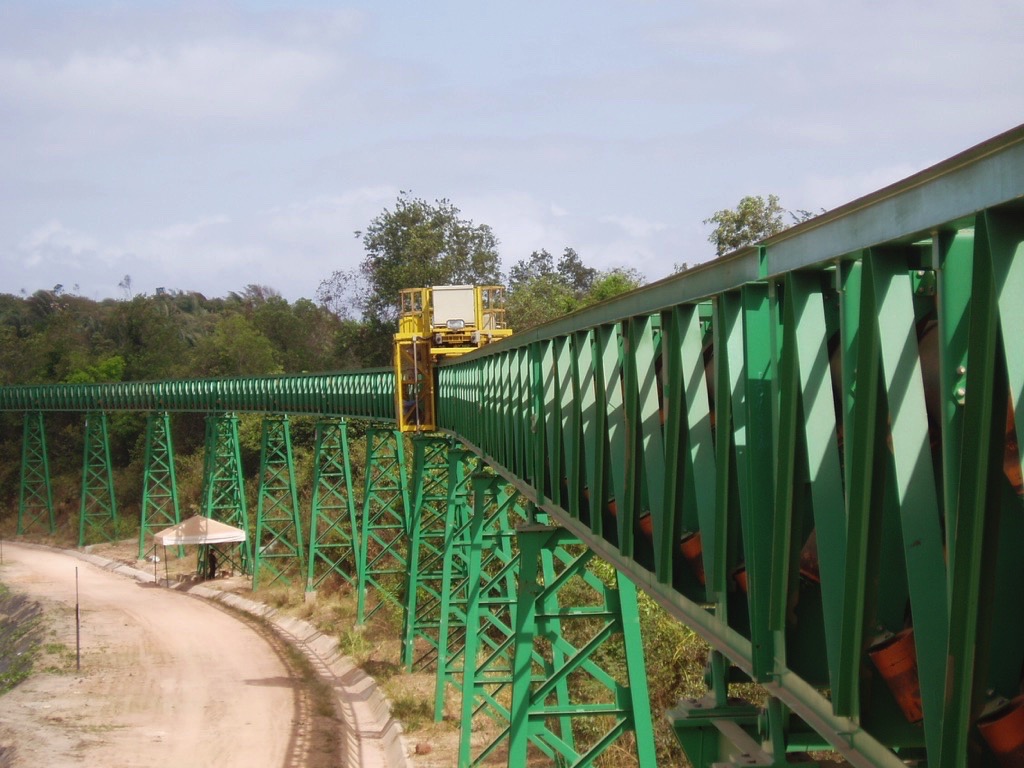
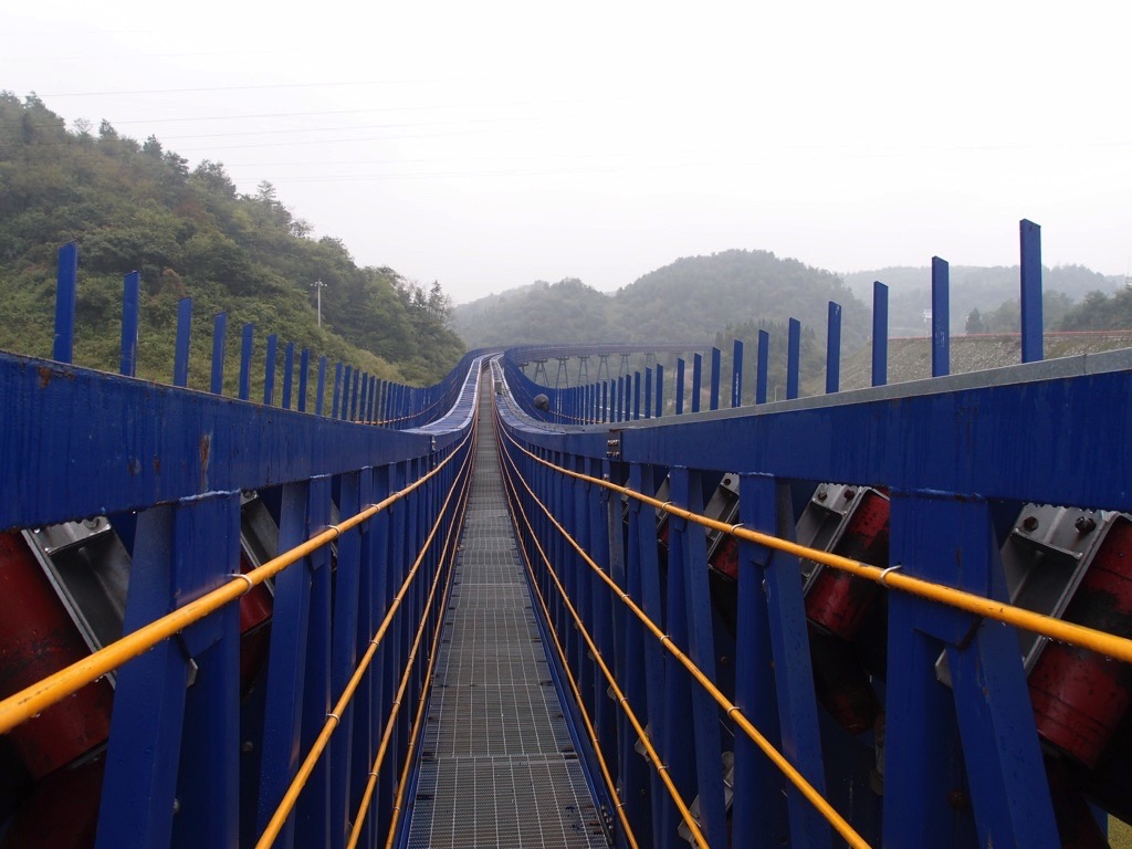
The Itaqui pipe conveyor system is located near the Port of Itaqui, Brazil. The design capacity is 1000 metric tons coal per hour. There are two conveyors: a 4.3 km long first flight (PC1), using a 375 mm diameter Goodyear ST1400 pipe belt, and a 0.6 km long second flight (PC2), using 375 mm diameter Goodyear EP800 pipe belt. Conveyor Dynamics was hired by Tecnometal Engenharia from Brazil to design the conveyor system and carry out data acquisition after commissioning. Tecnometal Engenharia supplied the detailed engineering, equipment and erection for this project. Conveyor Dynamics also worked with the belt supplier, Veyance Technologies, Inc., to design the pipe belts. The conveyor system was dry commissioned in August, 2012. The PC1 conveyor is shown in Fig. 1. This project has several highlights:
- The 375 mm diameter ST1400 pipe belt uses an improved LRR bottom cover. Its indentation rolling resistance is lower than typical LRR rubber, thus given the name Super Low Rolling Resistance (SLRR).
- The PC1 conveyor replaces the conventional walkway with a self-powered maintenance trolley. The installation of this maintenance trolley reduces the weight and cost of conveyor steel structure, and maintenance labour as well.
- The pipe belt has a maximum speed of 5.2 m/s. This is the fastest belt speed for a long overland pipe conveyor currently known to the author.
- The PC1 conveyor has very difficult horizontal curves. The conveyor route in plan view is shown in Fig. 5
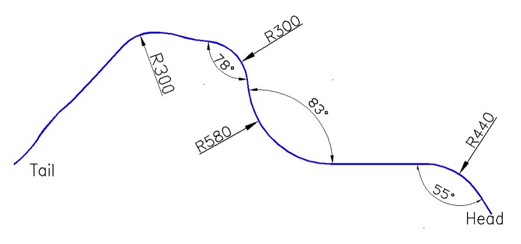
The 4.3 km PC1 conveyor has difficult horizontal curves, which were originally deemed as not suitable for steel cord pipe belt. There is one 300 m radius horizontal curve turning 78 degrees, one 580 m radius horizontal curve turning 83 degrees. Because of the difficult horizontal curves, a high stiffness pipe belt was designed. The high belt stiffness reduces the pipe belt deformation during horizontal curves and increases the belt stability against rotation.The high belt stiffness inevitably increases power consumption and belt tension. As a result, the design is an optimising process aiming to reach balanced belt stiffness. The pipe belt stiffness was analysed extensively through experimental testing and FEA, following the methodology outlined in Section 2.2.By adopting the SLRR belt, not only the power consumption is reduced, but the maximum belt tension is reduced as well. If using a conventional belt bottom cover, the high belt stiffness would cause excessive power consumption and belt tension. By using the SLRR cover, the power consumption and belt tension is mitigated. The lower belt tension is beneficial in two aspects. First, a lower rating steel cord belt can be chosen, the lower modulus of which is helpful for negotiating horizontal curves. Second, the lower belt tension reduces the pipe belt deformation during horizontal curves.After the conveyor was commissioned, Conveyor Dynamics carried out data acquisition on the Itaqui PC1 conveyor to measure the torque on drive shafts, takeup tension and displacement, and belt speed. The measured torque values on the drive shafts eliminates the uncertainties of drive efficiency. The results are summarized in Table 2.
| Belt speed [%] | Measured torque from strain gauge [%] | Calculated torque from PLC* [%] | Predicted torque for SLRR pipe belt [%] | Predicted torque for conventional pipe belt [%] | Predicted torque for conventional pipe belt [%] |
| 50 | 62.14±1.62 | 68.32±1.02 | 60.4 | 75.4 | 125.2 |
| 100 | 67.96±1.61 | 75.11±0.75 | 63.7 | 77.7 | 125.8 |
The measured value is very close to the initially predicted value for the SLRR pipe belt. The predicted torque values for using LRR and conventional bottom cover on the same belt are also shown in the table. Due to the system’s characteristics, a conventional belt would not have worked for this conveyor.
3.2 Kailin Pipe Conveyor System
The Kailin conveyor system has two identical, parallel pipe conveyors, with 6.2 km centre length and 103 m lift, commissioned in 2012 (Fig. 6). It is located in Guizhou province, China. The conveyors move through hilly regions, with multitude of horizontal and vertical curves. Conveyor Dynamics audited the conveyor system design, and worked with Veyance Technologies, Inc. in designing a 375 mm diameter, ST2500 Goodyear Confine pipe belt with LRR bottom cover.
The LRR Goodyear belt was installed on one conveyor. The other conveyor used a pipe belt from a different belt supplier, with the same pipe diameter and belt rating, but with conventional belt bottom cover. This parallel conveyor system provides the opportunity of side by side comparison between LRR and conventional pipe belt. The torque values from the drive control PLC are shown in Fig. 7, for both the LRR pipe belt (blue) and the conventional pipe belt (red), for both empty and loaded conditions. Fig. 7 is comparable to Fig. 3, only the vertical axis is torque ratio instead of horsepower. The reason for the different vertical scale is because the Kailin conveyor uses variable speed drives. The belt speed changes with tonnage, so torque is a better measurement than power. Based on the torque data, the author estimated the other conventional belt’s stiffness and calculated the predicted curve of torque vs. tonnage.
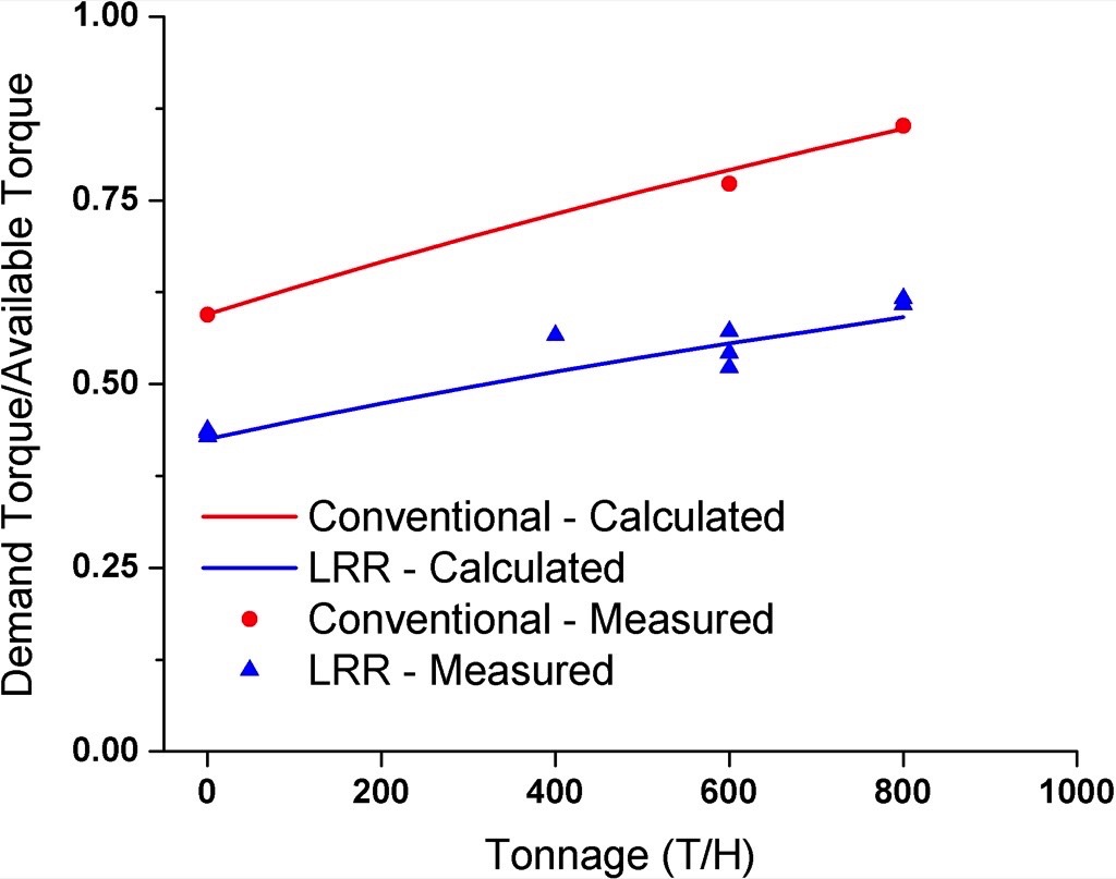
Between the two belts, there is approx. 35 % difference in torque demand for full load conditions, and approx. 30 % difference for an empty condition. As is described, the pipe conveyor power consumption is very much affected by the belt stiffness. Similarly, the effect of using LRR bottom cover is also affected by the belt stiffness.The percentage in power and tension improvement from LRR bottom cover will vary, depending on the belt stiffness and belt construction. Nevertheless, the reduction in demand torque is very substantial. The Kailin conveyors were originally equipped with 4 Å~ 800 kW drives. Because of the low power demand from the LRR pipe belt, the client was able to take one 800 kW drive off and store it as a spare.
3.3 Energy Efficient Operation
The installation of an LRR belt can achieve significant energy savings for pipe conveyors. Using the Kailin conveyor as an example, based on the 3.2 million metric tonnes annual tonnage, the current LRR belt will save about 4 million kWh per year compared to the conventional pipe belt. Accumulating over the belt life, the energy saving can be comparable to the belt cost itself.The additional power consumption for pipe conveyors, compared to trough conveyors, mainly comes from the extra contact pressure between pipe belts and idlers. As a result, the power consumption for running an empty pipe conveyor is high, compared to the full load condition. To minimize the power cost, empty running should be avoided, unless for maintenance purposes.Although the same is true for trough conveyors, avoiding empty running for pipe conveyors has a stronger effect on the operating cost. With Variable Frequency Drives, the power consumption can be reduced by adjusting the belt speed, depending on the material load, while keeping the same material cross section.Keeping the material cross section constant can also increase the pipe belt stability and reduce belt rotation. For long overland pipe conveyors, this can be achieved with a silo or stockpile at the tail, weight scales near the loading point, and VFD’s PLC control logic to adjust belt speed based on material loading.
4. Conclusion
Long overland pipe conveyor systems can transport materials in enclosed pipe belts and have small radii curves. However, the power consumption is typically double compared to a trough conveyor, incurring higher capital and operating costs. The Low Rolling Resistance (LRR) trough belt is a well-studied and proven technology. By combining numerical modelling and experimental testing, the LRR pipe belts can be analysed to optimise the design and operation of long overland pipe conveyors, and the benefits have been validated through several pipe conveyor projects.
A Note from the Editor
For all statements in this article that refer – directly or indirectly – to the time of publication (for example “new”, “now”, “present”, but also expressions such as “patent pending”), please keep in mind that this article was originally published in 2013.
Acknowledments:
References:
- Wiedenroth, J.: The longest pipe conveyor of the world with double load transport at Cementos Lima in Peru. SME Annual Meeting 2010, Phoenix, AZ, USA
- Stevens, R.: Belt conveying-belting the worlds' longest single flight conventional conveyor. bulk solids handling, Vol. 28 (2008) No.3.
- Hager, M., Hintz, A.: The energy-saving design of belts for long conveyor systems. bulk solids handling, Vol.13 (1993) No. 4.
- Wheeler, C., Roberts, A., Jones, M.: Calculating the flexure resistance of bulk solids transported on belt conveyors, particle and particle system characterization. bulk solids handling Vol. 21 (2004) No. 4.
- Nordell, L.: The power of rubber. bulk solids handling, Vol.16 (1996) No. 3.
- Kruse, D.: State-of-the-art data acquisition equipment and field measurement techniques for conveyor belts. In: Reicks, A., Myers, M.T. (ed.): Bulk material handling by conveyor belt 5, SME, Littleton 2004.
- Zhang, A.: Pipe conveyor and belt: belt construction, low rolling resistance and dynamic analysis. SME Annual Meeting 2012, Seattle (WA), USA.
| About the Author | |
| Dr. Yijun Zhang, P.E.Technical DirectorConveyor Dynamics, Inc., USA |
■

