
4. Indicators for Designing efficient Chutes
The following methodology has been recommended by one of our most eminent South African conveyor designers, Graham Shortt, for the design of conveyor chutes.
4.1 Chute Hoods
The chute hood should be dimensioned to cater for the following:
The side plates should clear the pulley face by a minimum of 50 mm. This distance is measured from the inside of any liner plates which may be attached to the chute hood.
The hood height at the material entrance should be at least 0.5 W, where W refers to the belt width. The height should allow sufficient space for the material burden to pass unhindered, including the possible incidence of larger rocks located on top of the normal burden. In this case, the minimum hood height should be in excess of 3 × bL, where bL is the maximum lump size.
The hood flanks and cover should extend backwards at least 850 mm from any nip point.
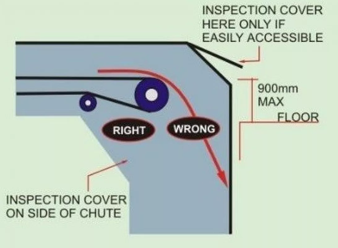
The hood may be provided with inspection or access openings, as required, located out of the material stream. The inspection openings should be easily and safely accessible. The inspection openings should be covered. For chutes that are de-dusted, the inspection and access openings should be designed to allow the minimum ingress of false air. The opening size must be sufficient for its purpose (see Table 1).
Where de-dusting is required, the hood should be provided with a back screen or apron seal, to limit the ingress of false air. The apron seal may be made of 3 mm (minimum) reinforced rubber cloth, attached to the chute hood entrance. The apron seal should be vertically slit to allow the material to pass. The slits are normally spaced at typically between 100 mm and 150 mm.
The hood is placed over the head or discharge pulley, which is located with respect to the equipment being fed. The location of the pulley is determined by consideration of the material trajectory over the pulley and the nature of the equipment being fed. The material trajectory is determined by the application of standard calculations. For conveyors discharging into hoppers and bins, the conveyor discharge pulley can be located to either feed the bin centrally when the bin is empty, or to allow central feed when it is full, as specified by the engineer. For cases where, for structural reasons, the bin must always be centrally loaded, the conveyor hood must be equipped with an adjustable impact plate or curved trajectory plate, in order to deflect the material stream into the desired path.
| Purpose | Height (min) | Width (min) |
| Observation | 300 mm | 250 mm |
| Servicing belt cleaners, sprays, etc. | 300 mm | 350 mm |
| Liner replacement | 450 mm | 600 mm |
| Maintenance personnel access | 650 mm | 650 mm |
4.2 Chute Body
The chute body should be designed to suit the transfer requirements, without changing the direction of the material severely. The area of the chute containing the body of the material flow must be at least 2.5 to 3.0 times the area of the material, based on the design capacity of the conveyor and the material speed at the point of consideration. The minimum area of the chute is then given by
|
|
where:
S = Material stream speed [m/s], (which could be belt speed)
D = Bulk density of the material [t/m3]
Cdc = Belt design capacity [t/h]
The chute body should be designed to centralise the material onto the downstream equipment. Material flow that tends to misalign the downstream belt is to be avoided. To this end, the use of ‘Vee’ bottom chutes is often encouraged, especially for in-line transfers from one conveyor onto another. For right-angled and skewed transfers, the use of adjustable impact plates or curved trajectory plates is recommended to change the direction of the material flow. The trajectory of the material will always impart some misalignment on a right-angle transfer. For this reason, the use of deflector plates is recommended. For material that is wet or prone to plugging, the impact plate ought to be designed to be self-cleaning, which may involve some test work.
(Fig. 4: Typical dead box design wp_1297)
The use of drop boxes is discouraged for material having a high content of fines or moisture or both. Drop boxes are also not always acceptable on conveyors handling diamondiferous material. Drop boxes may be designed for belts of relatively high speed (belt speeds in excess of about 2.0 m/s) that carry washed and sized material of lump size greater than 30 mm. Where drop boxes are specified, they should be designed to be self-draining. The base plate of the drop box must therefore be inclined at least at 10° to the horizontal plane. The drop box is then equipped with a replaceable lip liner, located to allow the passage of water underneath it.
(Fig. 5: Multiple dead boxes to reduce impact wp_1296)
The chute should be designed to minimise the impact height from one conveyor onto another, as far as the plant layout allows. The chute should be designed to minimise impact of the material on the sides of skirts on the conveyor being fed. The rear impact point of the material onto the conveyor is normally located 150 mm upstream of the first impact idler. Loading the conveyor in the transition zone from flat to trough is to be avoided as far as possible and should only be seen as a last resort.
Where the chute sides slope, the valley angle must not be less than the minimum slope angle for the material and liner combination. The valley angle is determined from the well-known equation as2
C = cot2A + cot2B (2)
where the angles A and B (the slopes of adjoining plates) are measured from the horizontal, and angle C is the valley angle, also measured from the horizontal.
(Fig. 6: Valley angle wp_1295)
The geometry of the chutes under silos and bins, feeding onto belt or apron feeders, are normally determined in conjunction with the material flow engineer.

