

Re: Pneumatic Grain Conveyor Design
Dear chavannilesh ,
how to design pneumatic grain conveyor?
I assume that your question is, how to design a pneumatic conveying system for grain.
Before starting to design, you must define several requirements:
-Grain pneumatic conveying properties
-Capacity
-Pipe routing geometry
-Vacuum system or pressure system
-Altitude above sea level
-Ambient conditions.
-Rotary valve feeding of nozzle feeding
-Rotary valve discharging
-Etc.
These data are required to estimate the pipe size, volume flow, pressure drop and filter size.
To perform these calculations, you must be familiar (expert) in the pneumatic conveying physics and systems plus the necessary field experience.
If this is your first installation, the time it takes to become that expert might be too long for the project.
Consulting a well known manufacturer of these type of systems is advised. ■
Teus
Re: Pneumatic Grain Conveyor Design
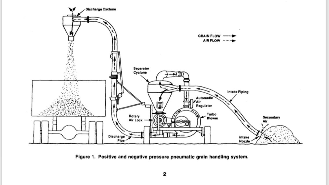
Please more explanation on working of pneumatic grain handling
Attachments
10fcbced-5599-44f1-9456-d3257b34a346 (PNG)
■
Re: Pneumatic Grain Conveyor Design
Dear chavannilesh
Your example of a pneumatic grain conveyor design is made by a company, which site can be visited at:
https://walinga.com/diesel-vacs
and
https://christianson.com/brands/vac-u-vator/
Designing such a conveyor system is rather complicated as the compressor fan is acting partly as a vacuum fan and partly as a compressor.
That results in the situation that the vacuum conditions influence the pressure conditions.
The pneumatic conveying principle is extensively described in many books and articles.
The main conclusion is that the principle is easy, but the technology and the mathematical calculation is very complex.
The complexity is that there are more variables than equations and these can only be solved by an iteration algorithm
And, as gas is used for conveying, the gas laws must be used to calculate the resulting velocities and pressures along the pipeline, while the gas is expanding.
The internal energy drop of the gas is used to cover the energy losses of the conveyed material, gas losses, elevation losses, bend losses, acceleration losses and additional losses, requiring a numerical integration algorithm.
more explanation on working of pneumatic grain handling
Many books, thesis’s and articles are written about pneumatic conveying, never leading to a user friendly and accurate calculation algorithm.
The calculation of pneumatic conveying installations require the knowledge of the physical laws (Newton Laws, Gas laws, thermodynamic laws, flow dynamic laws)
Many designs are based on the rule of thumb and a lot of field experience of a built gamma of machines.
Again, consulting a well-known manufacturer of these type of systems is advised. ■
Teus
Re: Pneumatic Grain Conveyor Design
Thanks for your reply sir. is there special type of centrifugal fan is used for this type of pneumatic conveying. I want to convey corn.capacity -30 ton per hour.conveying distance -30 mtr. Is it possible with centrifugal fan.what is multistaging in fan to get more pressure. In our area fan manufacturers gives maximum pressure 1500 mm WC . ■
Re: Pneumatic Grain Conveyor Design
Dear chavannilesh,
If you are still need a suction/pressure unit, whereby the inlet of the centrifugal fan serves as vacuum pump and the pressure side of the centrifugal fan serves as pressure pump and you want that design yourself, then you probably will not succeed, considering your questions
Study pneumatic conveying first at a proper education organization and then work some time for a pneumatic conveying company. (the road we all followed)
In your design:
The fan must generate an an equal air mass flow, which maintains the same grain flow at the corresponding vacuum and pressure.
Applying a centrifugal fan, this is not an easy task to design, as the fan curve is changing from high pressure drop at low air flow and high air flow at low pressure drop.
A fan with 2 impellers in series (multistage) can indeed generate more pressure.
In the past, I have calculated such a system and that took me days and days.
Balancing the inlet/outlet flow and inlet pressure drop with outlet pressure drop and accounting for the internal leakages of the cyclone and the rotary valve was an extremely complex exercise.
Again, consulting a well-known manufacturer of these type of systems is advise ■
Teus
Re: Pneumatic Grain Conveyor Design
Some manufacturers use roots blower instead of centrifugal fan what should we take care while we are using roots blower in this type of application ■
Re: Pneumatic Grain Conveyor Design
Dear chavannilesh,
Assuming that you are still referring to a vacuum/pressure unit whereby 1 compressor serves the vacuum side as well as the pressure side.
A lobe blower has the advantage of positive displacement, whereby the displaced volume is approx. constant.
That "simplifies" the calculations a lot.
Most of those units apply cyclones as material/air separators.
A cyclone is not 100% efficient, meaning that some dust is passing the vacuum/pressure compressor.
A centrifugal fan can withstand that better than a lobe blower.
To overcome this problem a filter assembly can be used instead of a cyclone, with some additional leaked air into the system. ■
Teus
Re: Pneumatic Grain Conveyor Design
While grains handling how much material to air ratio taken into account so that we can work smoothly. can we divide the dilute and dense with material to air ratio.in dilute phase conveying is there limit for material to air ratio.what are the calculations for selecting material to air ratio. ■
Re: Pneumatic Grain Conveyor Design
Dear chavannilesh,
The material to air ratio (also called Solid Loading Ratio, for short SLR) is not chosen.
The SLR depends on the conveying length and is valid for a certain airflow, pressure drop and a certain material.
In the pneumatic conveying governing formulas the SLR pops up as a, many times, returning value.
A pneumatic conveying calculation starts with gathering the known data:
-Pipe routing
-Capacity
-Material pneumatic conveying properties (particle size, particle density, bulk density, suspension velocity, material loss factor ambient conditions and additional pressure drop losses.
-Then you select a pipe diameter and compressor size and calculate whether the system is working (without choking) at the right capacity and pressure.
-If not, then select another diameter and repeat the calculation
This is an iteration approach of designing as the pneumatic conveying calculation itself is also an iteration algorithm.
The solid loading ratio will follow. ■
Teus

Pneumatic Grain conveyor design
how to design pneumatic grain conveyor ? ■