
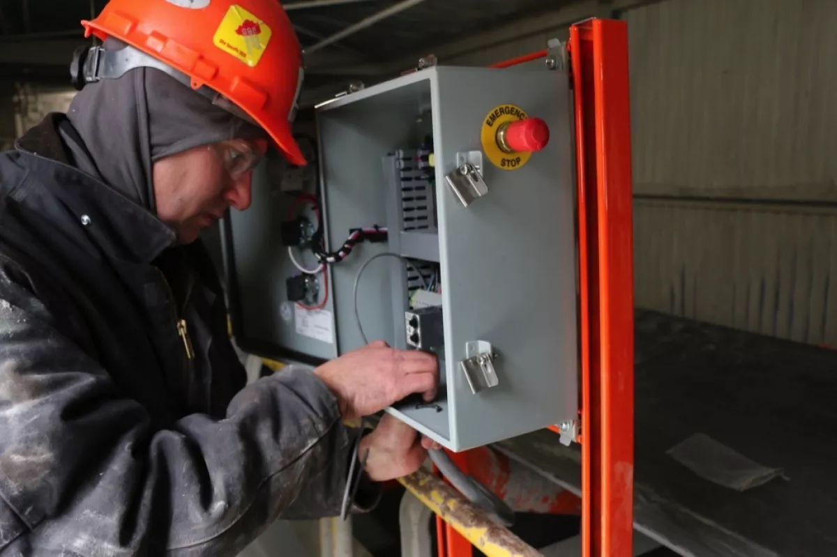
“Basically, a plant utility person would have to be stationed at the transfer point at all times, operating an air lance to prevent material from plugging the chutes,” explained Ash Grove Quarry Superintendent Quentin Vandal. “The approach required a staff member to poke and prod the accumulation for an entire shift to maintain the flow of raw material and keep pace with our production needs.”
Vandal recognized that air lancing was not a sustainable solution, and that the temporary fix was affecting overall efficiency, raising costs and taking a valuable employee away from more productive tasks. The plant had used air cannons from Martin Engineering in other locations at the facility to maintain material flow and prevent blockages. But the situation on Conveyor 102 was unique, in that no power was readily available to run the devices. Vandal turned to conveyor experts at Martin to review the issues and come up with a solution.
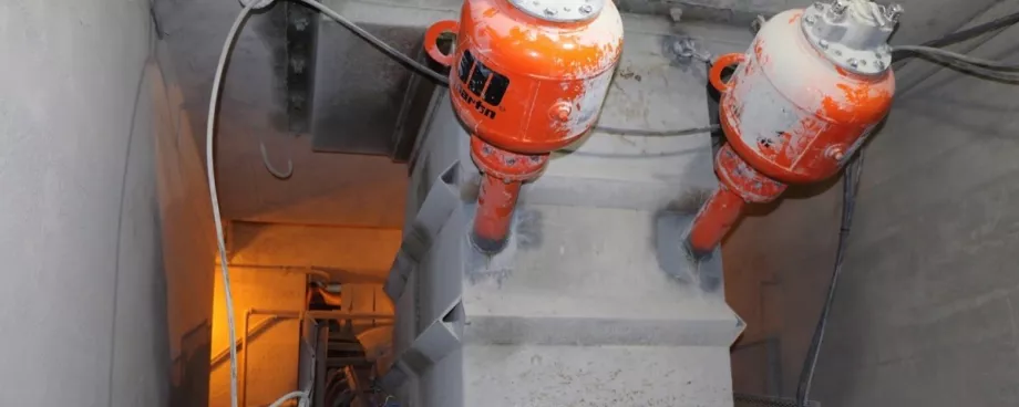
The first step was installing Martin’s innovative air cannon designs at key locations throughout the transfer point. One was located at the head of the conveyor, with two others at the tail. “The cannons did a good job of breaking loose the accumulation, but because they were connected to the plant’s air supply without electrical power, the units had to be fired manually,” explained Martin Territory Manager Cory Goldbeck. “So when plant personnel noticed a reduction in material flow, they would walk to the conveyor and trigger the cannons. This wasn’t a permanent solution, because at times the firing was a little too late, and that would require another round of air lancing.”
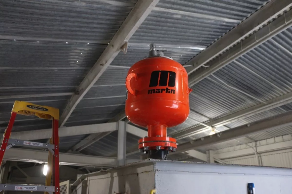
One cannon was located at the head of the conveyor.
|

Two other cannons were located at the tail.
|
Tapping into Kinetic Energy
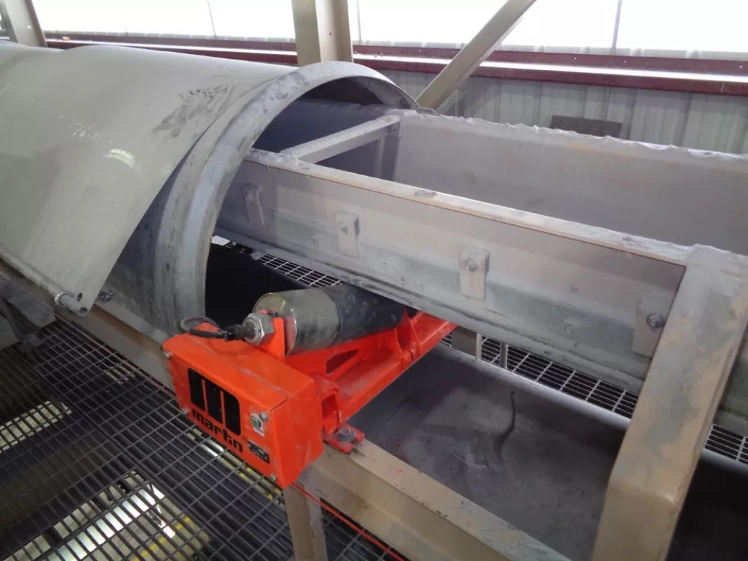
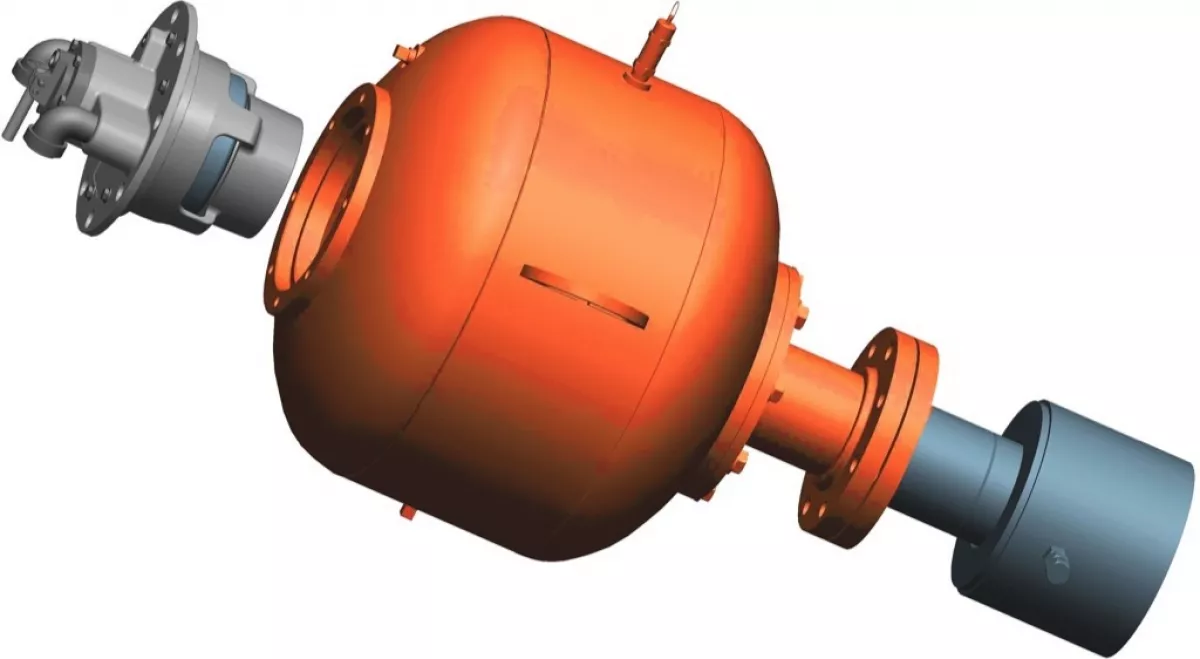
To address the lack of readily available power, Martin technicians installed the company’s Roll Generator System, a unique design that uses the energy of the moving conveyor to generate electricity.
“A conveyor is driven by a multi-kilowatt motor, and this power is readily available system-wide in the form of the moving belt,” Goldbeck continued. “The motors driving the belts are typically sized with a considerable power safety factor to account for parasitic loads, such as rolls with damaged bearings, tracking devices, sealing systems, belt cleaners and material changes due to different moisture levels and variable loads.”
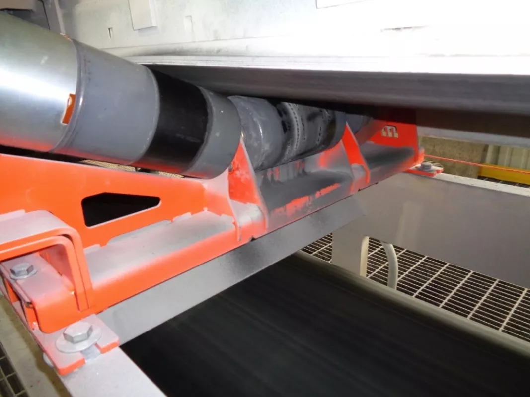
Currently available only in the USA, Martin’s product engineers developed the patented design that uses a magnetic coupling attached to the end of an existing roller. The outside diameter of the generator matches the diameter of the roll, but places the generator outside the material path to avoid the heavy loads and fugitive material that tended to damage previous design attempts. The system easily generates enough energy to power the air cannons, allowing operations personnel to schedule automatic firing and prevent the accumulation that had been creating flow problems. Together, the components created a turnkey solution that requires no human intervention.
The generator forms a lightweight unit that does not affect the existing roll in any way, except to be magnetically engaged and draw a small amount of mechanical power in order to generate the electrical energy. It’s sealed from fugitive material and forms an integral unit independent of the conveyor roller. All components to “condition” the power to a steady 24VDC are enclosed in a protective cabinet.
The Anatomy of an Air Cannon
The Martin air cannons are a positive-acting, internal valve design, developed specifically to deliver the most direct air path and maximum force output, with minimal air consumption. By producing more power from less air than most existing designs, it can employ a smaller reservoir, giving it a reduced footprint and allowing it to fit into tighter spaces.
During the firing sequence, a solenoid valve sends a signal to the exhaust valve, causing it to actuate and release the pressure holding the piston. The piston is instantly forced back by the air pressure stored in the tank, and the blast of air is then directed through the nozzle and into the target area. Refill time in this application is less than 30 seconds, and the current schedule has the cannons firing once every two minutes. Engineered to fire only when the belt is running and loaded, the system eliminates wasted air from firing when there’s no cargo on the belt or when the conveyor is idle.
The specially-designed valve allows the control solenoid to be positioned as far as 200 feet (60 meters) from the tank, keeping critical components away from harsh service environments. Locating the tanks in a safe, easily accessible area means that workers can inspect the equipment more often and perform service on a single cannon without downtime.
The design was developed for simplified maintenance, as the complete valve assembly can be removed by a single worker in one easy step, working from one side of the tank. The units are warranteed for a minimum of 200,000 firings.
Results
The air cannons are reported to be functioning as designed, significantly reducing the need for air lancing and preventing the buildup of material that was affecting production. “The process experiences less downtime associated with wet material plugging the chutes, feeders and storage bins,” said Vandal. “Operators are able to stay on task performing inspections instead of investing labor in time-intensive air lancing during operations. The ability to generate the necessary power right at the point where it was needed was a key element in the solution.” Vandal estimates the payback period at 1 to 1.5 years, adding, “The solution is worth its weight in gold.”
“The most valuable payback is improved safety,” he concluded. “With this automated system, we’ve dramatically diminished the risk of potential injury, reducing personnel exposure to unnecessary safety concerns associated with air lancing. We’re very happy with the outcome, and with the level of expertise and service overall from Martin Engineering.”
About Ash Grove Cement
Ash Grove Cement is the 5th-largest producer in the United States, shipping 8.3 million tons of Portland and masonry cements from eight plants nationwide. Founded in 1882, the firm currently operates 27 cement terminals and two deep-water import terminals, as well as extensive ready-mix operations and a major quarry operation in British Columbia.
■
