The centre of the sample and centre of the bottom plate were marked. The precise overlap position was controlled by placing the belt sample in such a way that the marks had to coincide in case of the top overlap position, or form a required angle, representing the angle of twist by rotation the sample clockwise (see the reference cross sections in Fig. 2).
For the experiments two types of the belt construction were used – a steel cord belt specially designed for pipe conveyors (one sample), and a fabric belt designed for a conventional trough belt conveyor (two samples with different belt widths). The information regarding the properties of the samples and tested ratios between belt width and pipe diameter are presented in Table 2.
| Sample N° | Belt type | Belt width [mm] | B/D [-] | |
|---|---|---|---|---|
| 1 | Steelcord | ≈ 1800 | ≈ 4.0; 3.6; 3.4; 3.0 | |
| 2 | Fabric | ≈ 1600 | ≈ 3.5 | |
| 3 | Fabrik | ≈ 1200 | ≈ 3.0 | |
| Sample N° | Troughability | Mass [kg] | Overlap position (see Fig. 2) | Tension |
| 1 | 0,334 | 10.4 | Top; Bottom | no |
| 2 | 0.398 | 4.9 | Top | no |
| 3 | 0.368 | 3.7 | Top | no |
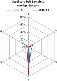
The test results were acquired during a period of about 5 minutes at a sample rate of 1 Hz and averaged in absolute values. Figure 8 illustrates the results of the contact forces for the different belt samples and ratios between belt width and pipe diameter for the overlap position on the top. Fig. 9 shows the form forces behaviour only for the steel cord sample 1 with overlap position on the bottom.

In general, a decrease of the pipe diameter with a sample of a specific width leads to an increase in the contact forces (in absolute values). The exception represents the case of “no overlap” (the ratio B/D ≈3.0) due to the appearance of the repulsion forces phenomenon at the edges. Both fabric samples exhibited low transverse rigidity and poor ability to form a stable pipe shape, as may be expected for a fabric belt intended for a conventional trough belt conveyor. Sample 3 did not form a tight seal on the overlap; Sample 2 collapsed its pipe shape, as can be observed from the contact loss with all three top idler rolls in Fig. 8b.

This test rig configuration is perfectly suitable for studying the effect of the viscoelastic properties of belt rubber compounds on contact forces behaviour, as it is capable to acquire data for each case during more than experiments lasting 24 hours. However, the relaxation effect was not considered in the described experiment due to practical considerations. The reason was that for the test case, the belt samples had to be stored in flat shape for a quite substantial time period in order to eliminate the initial deformation from the previous tests.
The test results confirmed that the belt properties and also the belt width and rate of overlap had a great influence on the load distribution between the idler rolls and on ability of the belt to form a stable pipe. That is why it is important to develop a uniform standard connecting all significant parameters. For example, the pipe diameter can be changed by either varying the length of the overlap, or by selecting a different belt width and keeping the rate of overlap versus belt width constant. In general, in order to form a stable pipe shape, softer belts require a higher rate of overlap, which need to be at the range B/D = 3.5…4. If the rate of overlap is preserved constant for all the manufacture belt widths, belts with higher transverse bending stiffness need to be selected for wider widths, i.e. for bigger pipe diameters.
3. Conclusion
Summing up for the paper Part A, it is important to emphasize, that all the six-point stiffness testing devices, described in this paper had a number of significant advantages. Due to low manufacture, installation and assemblage costs, their mobility and simple test performance, this type of test rig design together with the troughability test can be considered sufficient for identifying a belt’s ability to form a stable pipe for conveyor belts with different transverse bending stiffness, pipe diameter and rate of overlap. Positive and negative aspects inherent to the test rigs of this kind are highlighted in the list below. As a central disadvantage, six-point belt stiffness testing devices are not suitable for studying belt behaviour in curves and tensioned belts. For that purpose other test set-ups were designed and installed with various frames and supports, modelling pipe conveyor sections of actual size.
| Advantages | Disadvantages |
|---|---|
|
|
This type of the test rigs will be explicitly discussed in the following Part B of this paper.
■


