

Dense Phase System Conveying Rates
I use an Excel-based method to calculate the conveying rates for dense phase pneumatic conveying systems. This method will be described in an article that should be published in the next few months.
For the time being you may use my article "Debottlenecking Pneumatic Conveying Systems" published as a cover story in the April 2004 issue of Chemical Engineering. This article covers all of the variables that affect the capacity of dense phase conveying systems.
Regards,
Amrit T. Agarwal
Consulting Engineer
Pneumatic Conveying Consulting Services
Email: polypcc@aol.com
Ph and Fax: 304 346 5125 ■
Re: Transfer Rate Prediction Dense Phase System
I think you are jumping ahead for your system design first of all you need to look into a number of other parameters before you can calculate the transfer rates / pressure drop for a dense phase system. First of all you need the size of the blowtank. Then is it going to be single blow tank system or two in series or parallel? By the looks of it single blowtank with 5” pipeline and 5-10 elbows is bit ambitious for these flow rates.
Transfer rates only does not give the total conveying rates, as the dense phase cycle consists of “valve opening - blowtank filling –valve closing - pressurising-conveying - blowdown”. The vent line after the cyclone is also very long and if its length cannot be reduced the pipe diameter should be increased to reduce the air only losses in the vent. ■
Re: Transfer Rate Prediction Dense Phase System
You should find all you want in the "Handbook of Pneumatic Conveying Engineering" (written by myself and two colleagues) and published last year by Marcel Dekker. Chapter 13 is devoted to the pneumatic conveying of "Cement and Drilling Mud Powders". This includes conveying data on barite, bentonite, and oil well and OP cements. Figure 13.12 gives data for barite conveyed through a four inch single bore pipeline of similar length to yours and shows that with an air supply pressure of 35 psig and 200 cfm you will get about 80 ton/h (using a top discharge blow tank). With a five inch bore pipeline and a higher air supply pressure you should achieve the flow rates that you require with all three materials.
The 200 cfm in the above case is the total air flow rate. Part of this air flow is directed to the blow tank and the rest is introduced into the pipeline immediately after the blow tank. This is the means of controlling the discharge rate from the blow tank and this is covered in Chapter 2.
The 80 ton/h in the above case is the steady state flow rate. As mentioned in the previous reply, you must also consider the size, number, valving arrangements and cycling frequency of the blow tank to achieve your 80 to 120 ton/h on a time averaged mean basis. A review of these options is also given in Chapter 2. ■
Software
Avoid commercial software for conveying systems, the disclaimers accompanying them are a testament in themselves. Typically the calculations used in these programs are proprietary and wholly inaccessible to the user. I trust in God, not in calculations that I can not see.
I suggest that you develop your own program that is tailored to your specific requirements, excellent resources are available to help you along. Then you would have useful tool, i.e. a program based on first principles that can be verified for its accuracy.
Dennis Hauch, PE ■
Transfer Rate Prediction Dense Phase System
... ■
Transfer Rate Prediction Dense Phase System
Dear Gentlemen,
Many thanks for the valuable comments, especially advice from Dr Mills and Dennis.
Kind Regards
Ken ■
Re: Transfer Rate Prediction Dense Phase System
Our firm offers a well proven design software called PNEUCALC which has over 20 years of proven track record behind it.
It is updated based on actual field results and can be used to solve for various parameters.
Contrary to some of the previous comments, you can trust some commercially available software as it is no different than doing your own calculations by hand from textbooks or other references except that it is quicker and alot more flexible.
It is ideally suited for the products and application you have mentioned.
I'd be happy to provide more details if you so desire. Just send me an e-mail to the address below.
Regards ■
Re: Transfer Rate Prediction Dense Phase System
I am a little bit confuse...... ■
Re: Transfer Rate Prediction Dense Phase System
Ken
What's confusing you? ■
Pneumatic Conveying Calculations
My article "Theory and Design of Pneumatic Conveying Systems" was published in Powder Handling and Processing magazine in its April 2005 issue. This article gives all of the equations that are needed to run calculations for pneumatic conveying systems and to understand what and why every thing is happening. Only a basic knowledge of Excel is needed. A PDF copy is available from me.
Regards,
Amrit T. Agarwal
Consulting Engineer
Pneumatic Conveying Consulting Services
Email: polypcc@aol.com
Ph and Fax: 304 346 5125 ■
Re: Transfer Rate Prediction Dense Phase System
Another “cold case”,
Mr. Ken T asks:
Material : Cement, Barite or Bentonite
Transfer dry bulk from blow tank to process plant.
Blow tank is with top discharge pipe.
Compressed air is fed into blow tank through 6 to 10 nozzles for fluidizing effect and conveying of powder.
Distance of blow tank to process plant : about 100ft to 150ft
Conveying pipe size : 5 inch
Pipe elbows along conveying pipe line : about 5 to 10
Compressed air pressure (to blow tank) : 40 to 70 psi
Compressed air flow rate (to blow tank) : 300 to 700 cu.ft / min
Compressed air pipe size : 3 inch
Dense phase system
Expected transfer rate : about 80ton to 120ton per hour
Other conditions, vent air from process plant will pass through a cyclone separator before being piped to atmosphere (5 inch with 50ft, 3 elbows).
The description indicates a pneumatic conveying system for a drilling platform.
The given parameters are varying quite a lot, which makes a precise answer difficult.
Could someone recommend a good software suitable for following system performance prediction, or provide some guidance so that I can do the prediction effectively with a spread sheet.
“good software” is as good as the accuracy of the used algorithms and there representation of all the involved physics.
Then, the user has to understand and be familiar with the physics, the mathematical approach of the algorithms and the practical technology of pneumatic conveying.
(Knowledge and behavior of built installations)
This is not an overnight study and a spreadsheet program will not be useful if accuracy is required. Copying built installations will give better results.
Case 1, would like to predict the bulk transfer rate by fixing the compressed air pressure and flow rate.
To answer this question, the compressor flow rate has to be fixed and for a selection of compressor air pressures, calculate the transfer rate.
This must be executed for a selection of compressor air flows.
The result is a 3 dimensional table.
Too much work.
Case 2, would like to determine the compressed air pressure by fixing the transfer rate. Hence, determine the compressor size.
I calculated:
horizontal length = 7m
vertical length = 30m
bends = 8
Diameter 5”(128 mm)
Compressor: 25 m3/min at 4.5 bar
Conveying rate cement = 105 tph at 4.5 bar (bends start to fill up)
Conveying rate barite = 101 tph at 4.5 bar (bends start to fill up)
Conveying rate bentonite = 101 tph at 4.5 bar (bends start to fill up)
These operating points are at the lowest point of the Zenz diagram and therefore the maximum capacity with this airflow.
Would like to have more feedback from forum members.
Have a nice day ■
Teus
Re: Transfer Rate Prediction Dense Phase System
Dear Teus,
on the basis of my general state diagram, developed with the aid of operating data from industrial conveying systems, I have to offer for example the following results for your "case 2", whereby the vertical pipe length is increased by a factor of 2, and each pipe arc has been taken into account with an additional length of 1 m.
1. Operating point at the boundary of the dense phase area to the unstable area
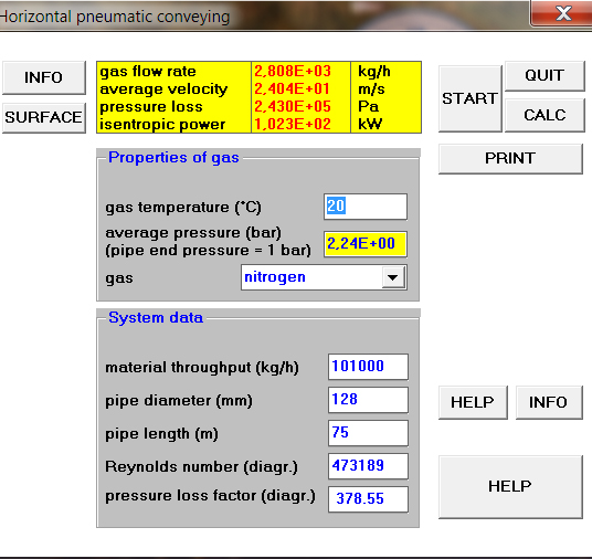
2. Operating point in the dense phase at a distance to the edge which is often to be found
What do you think?
Regards
Manfred Heyde ■
Re: Transfer Rate Prediction Dense Phase System
Dear Manfred,
I understand that case 2 is remodeled by you, according to:
horizontal length = 7m becomes 7 m
vertical length = 30 m becomes 60 m
bends = 8 becomes 8 m
Giving a total equivalent length of 75 m
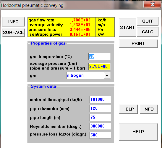
Then you calculate the system for 2 gas flows:
1)nitrogen 25 m3/min = 1780 kg/hr
2)nitrogen 39 m3/min = 2808 kg/hr
For a capacity of 101 tons/hr (cement, barite or bentonite), the calculated pressure drop is:
1)3.44 barg (I calculated 4.5 barg, conveying gas air)
2)2.43 barg
It is difficult to interpret the calculation results as the used algorithms are not really comparable.
What we actually need is a measured installation.
Have a nice day ■
Teus

Transfer Rate Prediction Dense Phase System
Good day,
I am working on a bulk transfer system. Prediction on system transfer rate is required. Could someone recommend a good software suitable for following system performance prediction, or provide some guidance so that I can do the prediction effectively with a spread sheet.
Material : Cement, Barite or Bentonite
Transfer dry bulk from blow tank to process plant.
Blow tank is with top discharge pipe.
Compressed air is fed into blow tank through 6 to 10 nozzles for fluidizing effect and conveying of powder.
Distance of blow tank to process plant : about 100ft to 150ft
Conveying pipe size : 5 inch
Pipe elbows along conveying pipe line : about 5 to 10
Compressed air pressure (to blow tank) : 40 to 70 psi
Compressed air flow rate (to blow tank) : 300 to 700 cu.ft / min
Compressed air pipe size : 3 inch
Dense phase system
Expected transfer rate : about 80ton to 120ton per hour
Other conditions, vent air from process plant will pass through a cyclone separator before being piped to atmosphere (5 inch with 50ft, 3 elbows).
Case 1, would like to predict the bulk transfer rate by fixing the compressed air pressure and flow rate.
Case 2, would like to determine the compressed air pressure by fixing the transfer rate. Hence, determine the compressor size.
Please provide comments on other considerations so that better accuracy prediction can be achieved.
Thank You
Ken ■