The concept of the so called “intelligent garland” is based on an elastic suspension (spring system) which continuously adjusts the troughing angle to the actual loading condition. This spring system entails a strong shock absorbance which in turn also positively affects both idler service life and noise emission. The general function of the intelligent garlands will be investigated within a research project. For the field measurements in Mibrag’s open pit mine “Vereinigtes Schleenhain’; a belt conveyor with a length of 600 metres was equipped with intelligent garlands. This article introduces both the concept of the intelligent garland and the results of the first field tests.
1. Introduction
![Fig. 2: Measured idler forces depending on troughing angle. Source: [1]](https://www.bulk-online.com/sites/default/files/public/styles/basic_max/public/2023-01/bsh2012_05_07_Katterfeld_02_img.jpg.webp)
Following the advice of belt manufacturers, the troughing angle should not exceed 45°. Smaller troughing angles lead to smaller conveying capacities and also decrease the deformation of the conveyor belt. A smaller belt deformation causes smaller idler forces due to the decreased flexure resistance in the belt and in the bulk material. This relation is shown in Fig. 2.
In the present case, the increase of the troughing angle from 10 to 30 degrees causes four times higher idler forces. An increase to a troughing angle of 60 degrees leads to a further 50 percent of increase in forces. Hence, it can be concluded that higher troughing angles, in general, cause higher motion resistances.
2. The Concept of the “Intelligent Garlands”
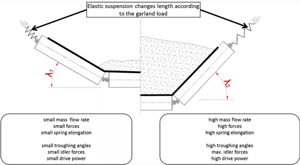
The first idea of an intelligent garland is shown in Fig. 3. The garland suspension consists of spring elements which change their length depending on the load on the garland and thus adjust the troughing geometry. Several patents [2,3,4] exist for such flexible troughing systems. All known solutions assume a special conveyor framework. The new concept of the intelligent garlands, however, will use the existing framework. It should also be noted that the existing solutions focus mainly on the relatively short load area of the conveyor belt and are aimed at dampening the impact of the bulk material on the belt.
Therefore, new ideas and concepts were developed which use a standard hook for the transfer of the main load to the framework. The springs are used only for changing the troughing angle. This concept is shown in Fig. 4.
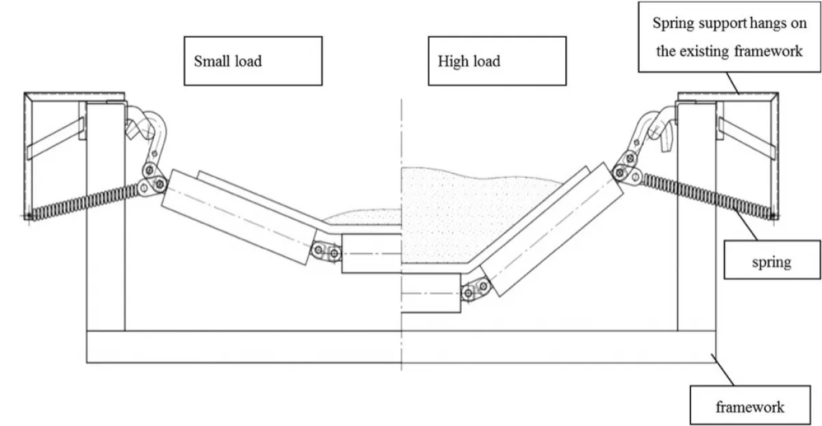
In the present concept (ed. note: publ. in 2012), the additional elements for the spring support are simply hung onto the conveyor framework. A spring is clamped between the spring support and the upper end of the side idler axis. The side idlers are pulled sideward by the spring force. The spring only transmits horizontal forces. The vertical forces are transmitted by the hook as with usual garlands. For high material loads, the garland geometry is the same as with standard garlands with a high troughing angle. The springs do not influence the maximum troughing angle. If, however, the belt is loaded with less than the maximum load, the forces acting on each garland are smaller. Here, the springs change the geometry and the troughing angle decreases. The choice of spring parameters, the design of the spring support and the length of the hook serve to optimise this concept of changing the troughing geometry.
3. Practical Realisation
The first prototypes of the intelligent garlands were produced and tested by company Artur Küpper. For the first test, five garlands were attached to a segment of a conveyor framework. The belt and the framework segment are original parts of a belt conveyor with the following parameters:
- belt width 2000 millimetres
- belt speed 6.55 metres per second
- nominal mass flow rate 14,500 tonnes per hour, (average approx. 7000 to 8000 tonnes per hour)
- garland distance 1.25 and 2.5 metres
- troughing angle 33 degrees
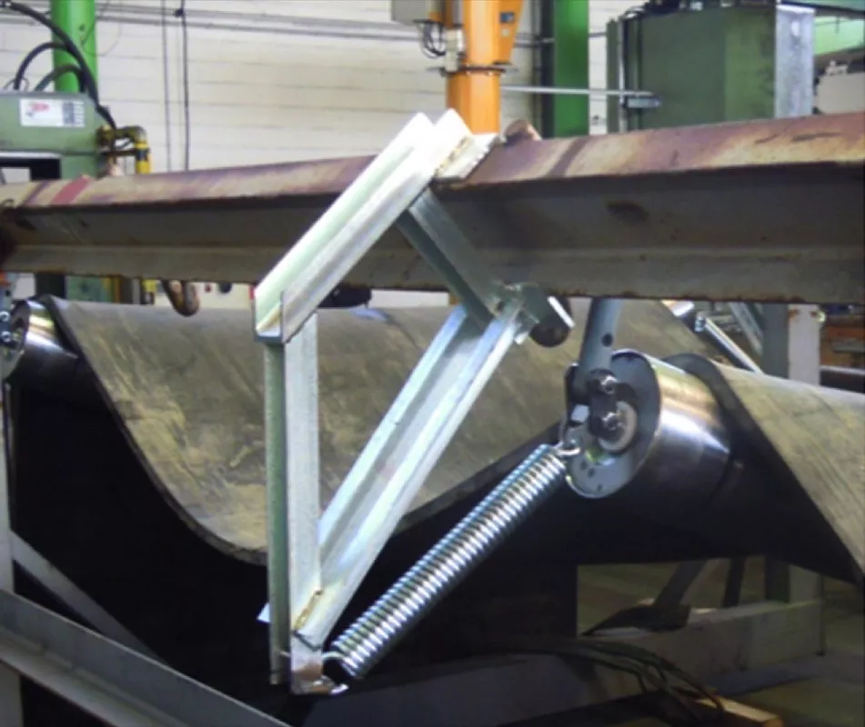
The test rig was equipped with the developed suspension system. The load of the bulk material was simulated to measure the change of the troughing angle. For this, steel bars were used instead of the bulk material. Although the weight of the steel bars was chosen to be equivalent to the bulk material weight, the load distribution on the belt segment was different due to the higher density of the steel bars. Hence, the whole weight of the steel bars acted on the central idler while in reality, the bulk material would also affect the side idlers. Also in contrast to actual conveyor operations, the belt was not tensioned in the test rig.
Fig. 5 shows the comparison of the first experimental tests and the simulation results. A good correlation can be seen between the experimental measurements and the results of several FEM simulations.
Changing the troughing geometry can be influenced by the choice of springs and the distance between the spring ends. Hence, it is possible to generate a specific behaviour of the troughing geometry for each belt conveyor. Especially for those belt conveyors with a deep trough of 45 degrees, a reduction of the troughing angle to 20 degrees will result in a significant decrease in power consumption. Troughing angles lower than 20 degrees have a higher risk of belt misalignment. Therefore, troughing angles below 20 degrees cannot be recommended.
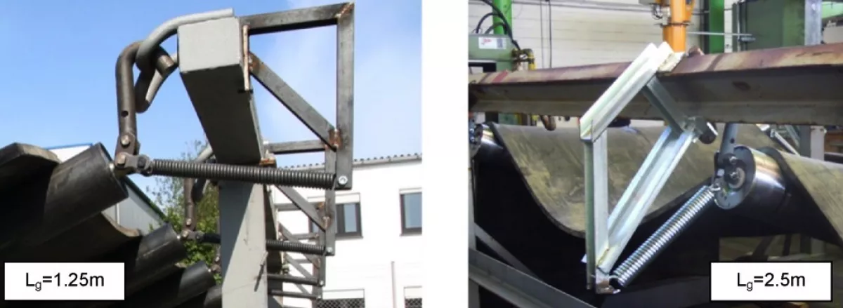
For industrial application, two systems were tested: one with a garland distance of 1.25 metres and one with a distance of 2.5 metres. As each system has its own framework design (U-profile instead of rectangular tube), different springs and spring support systems were developed. A comparison of the two systems is shown in Fig. 6.
4. Advantages of the intelligent Garlands
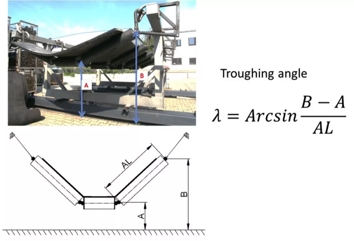
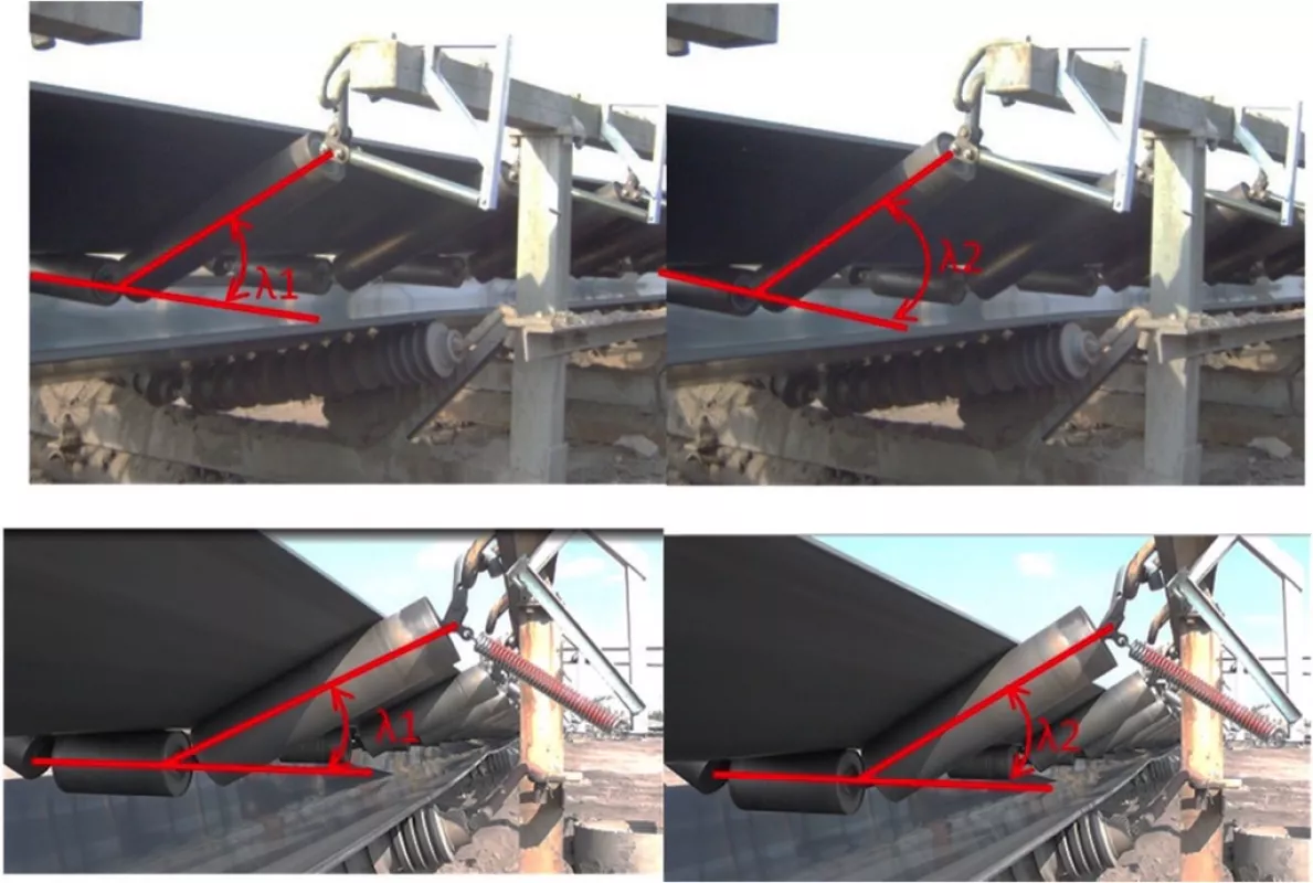
The main advantage of intelligent garlands lies in the constant adaptation of the troughing geometry to the current load on the belt. The troughing angle for different garlands can be measured as shown in Fig. 7.
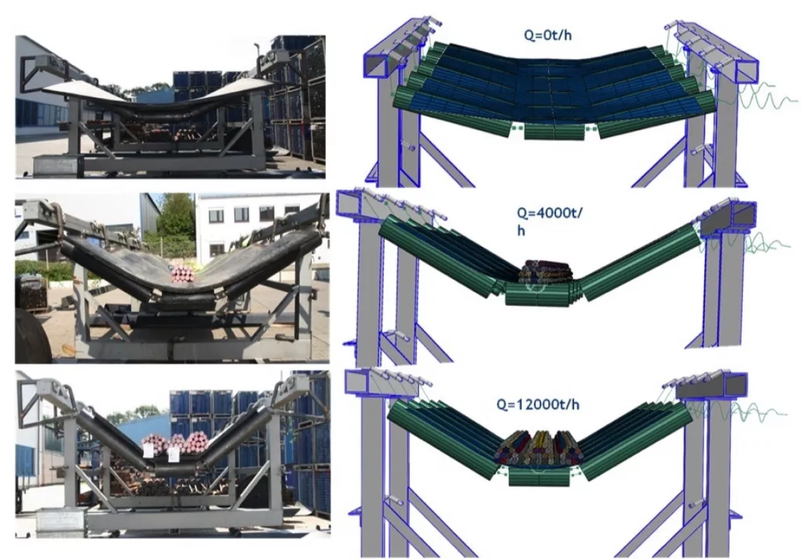
As described above, the belt load was simulated using steel bars. The geometry of the garlands could easily be measured in the test rig described above. In industrial application, such a measurement would be much more difficult due to the return strand of the conveyor and the belt movement. Fig. 8 shows the measured and calculated changing of the troughing angle depending on the simulated mass flow rate.
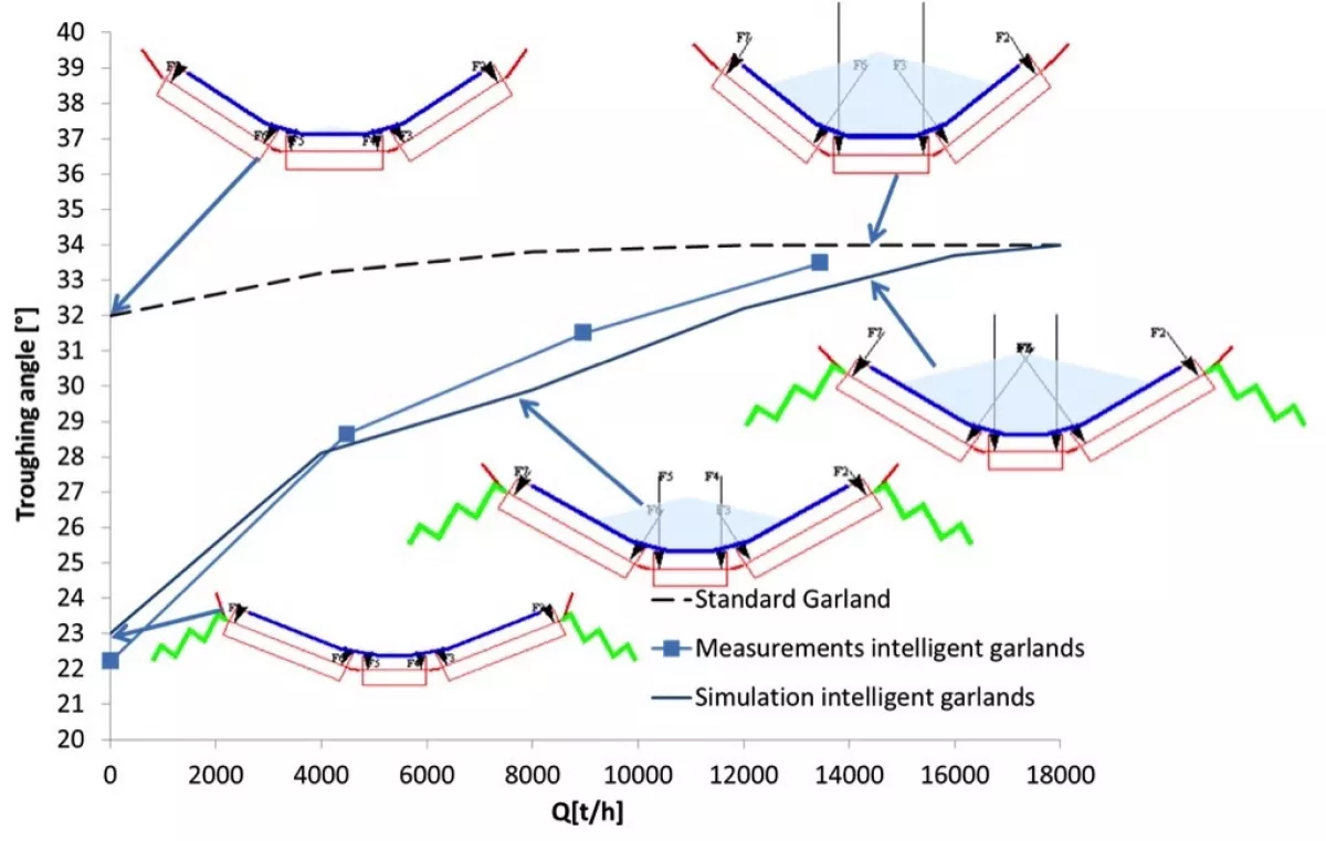
Additional forces on the side idlers are generated by the intelligent garlands. The troughing angle of the test rig changes from 22 to 33 degrees. The smaller angle occurs for smaller belt loads, causes smaller forces on the rollers and hence a smaller motion resistance. Apart from reducing the motion resistances, several other advantages are generated if the developed intelligent garland is applied:
- Uniform force distribution along the length of a belt conveyor if the framework segments are different in height alignment and orientation.
- Increase of the idler and belt life time.
- Shock absorption in the case of very coarse and hard material like rock and overburden.
Differences in height alignment and orientation of the conveyor framework occur very often in shiftable belt conveyors plants which e. g. have to follow the excavation machines in a mine. These differences in alignment and orientation cause a non-uniform distribution of the garland load. Hence, one garland may carry twice the belt load because its neighbours are not in contact with the belt. The elastic suspension of the intelligent garlands can equalise these differences in alignment and orientation of the conveyor framework. Fig. 9 explains this problem in a diagram.

The indentation rolling resistance is the main motion resistance for a horizontal belt conveyor. The indentation rolling resistance (We ) is proportional to the load of a roller Fr, to the power of 1.33 [5]. Assuming a belt and idler depending on constant k, the indentation rolling resistance can generally be calculated as:
| (1) |
If one of three garlands has no contact with the belt, the total load will affect the other two garlands as shown in Fig. 9. In this case, the indentation rolling resistance for all three garlands can be calculated as:
| (2) |
If the load can be uniformly distributed between all three garlands, the above equation would look as follows:
| (3) |
Hence, it is may be assumed that if the load could be uniformly shared by all garlands, the indentation rolling resistance would be reduced by 13 percent. In industrial application, these differences may not be as prominent due to other influences. But the simple calculation above clearly shows that a uniform load distribution on the garlands reduces motion resistance.
5. Installing in Industrial Belt Conveyors
The first intelligent garlands were installed and tested under industrial conditions in the Mibrag lignite open pit mine “Vereinigtes Schleenhain” in Germany. Two systems with garland distances of 1.25 and 2.5 metres were tested.
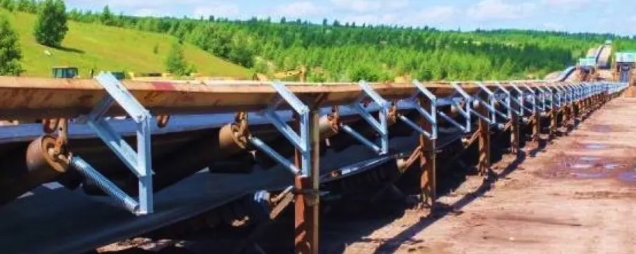
Due to the carefully crafted design, installation of the new garlands was easy and smooth. They could be installed without additional expenses, and no new devices or tools were needed for the installation. Fig. 10 shows the installed garlands.
After installation the following observations could be made:
- The troughing geometry of the intelligent garlands changes with the belt load.
- All intelligent garlands are in contact with belt each idler is rotating whereas some idlers of standard garlands close to the intelligent garlands do not rotate.
- The permanent elastic suspension dampens the impact of larger bulk lumps.
- Due to the short application distance (only 10 garlands were installed), a negative influence on the belt alignment could not be observed.
6. Field Measurements
Currently, measurements are running on an industrial belt conveyor to verify if the predicted reduction in power consumption for the intelligent garlands can be reached in industrial application. These investigations are the main task of a research project initiated by company Artur Küpper and the Institute of Logistics and Material Handling Systems of the Otto-von-Guericke-University in Magdeburg, Germany. This project was made possible by company Mi brag, which allocated a belt conveyor in their lignite open pit mine “Vereinigtes Schleenhain” as a test facility. The belt conveyor “GBF 50” has the following parameters:
- belt width: 2.0 metres,
- belt speed: 6.55 metres per second,
- bulk material: overburden,
- max. volumetric flow rate: 8500 cubic metres per hour,
- drive: 2 × 900 kilowatts (no frequency converter is used).
The main aim of the research project is the measurement of the power consumption of the chosen belt conveyor depending on the current mass flow rate. The power consumption will be measured using usual standard garlands and the new intelligent garlands to allow the analysis of the influence of the elastic suspension. For the measurements, the conveyor was equipped with new garlands of company Artur Küpper in May 2012. In this project, the following data are continuously recorded:
- electric power of the two drives on the head of the conveyor,
- torque on the shaft of the two drive pulleys. For this, the shafts are equipped with strain gauges as well as with a miniaturised amplifier with an integrated telemetric transmitter and a inductive power supply,
- mass flow rate via a belt scale on the feeding conveyor of GBF SO, and
- weather conditions.
Currently (ed. note: publ. in 2012), measurements are running with standard garlands.
To ensure a wide data base, these measurements last several weeks. After this measurement phase is completed, the conveyor will be equipped with the elastic suspension to allow measurements with intelligent garlands. The same idlers will be used for the tests. Only the suspension will be changed.
Each measurement phase will last several weeks to allow a comparison of the data for garlands with and without elastic suspension, although the mass flow rates and the weather conditions may not be the same in every moment.
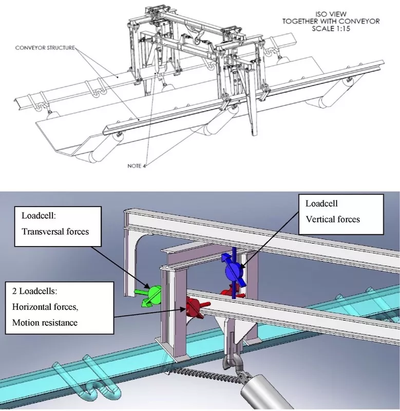
Furthermore, it is planned to measure the garland load and motion resistance in more detail on a single garland. For this, a special measurement portal was designed which allows the measurement of the force on a single garland in all three spatial directions. The portal was developed by the Mining Institute of the Technical University of Wroclaw, Poland, under the guidance of Prof. Lech Gladysiewicz. The Mining Institute has had positive experiences with this measurement portal for many years and uses it for field measurements in the lignite open pit mine Belchatow [6]. The portal is shown in Fig. 11 and is currently in production. The force on a single garland will be measured for both standard and intelligent garlands.
Conclusion
Company Artur Küpper has developed a system which allows an adaptation of the troughing angle to the current mass flow rate. For small loads, the troughing angle of the belt conveyor is shallow (e.g. 22 degrees). For the nominal mass flow rate, the intelligent garland lowers the position of its central idler and reaches the troughing angle of a standard garland (e.g. 33 degrees).
The elastic suspension of the intelligent garlands can be smoothly installed in existing belt conveyor frameworks. Hence, a conveyor can quickly be equipped with the new system. Additional changes on the framework or new installation devices are not necessary. The theoretical analysis shows several advantages of the intelligent garland, such as:
- the reduction of the power consumption,
- the uniform load distribution on all garlands also for poorly aligned conveyor framework segments,
- an increasing of the idler life time,
- a reduction of framework vibrations, and
- dampening of the impact of large lumps (rocks) on the idlers.
The first tests and field experiments prove the predicted behaviour of the new garlands. The first five garlands have already been working under the rough conditions of an open pit mine for one year. So far, no significant disadvantage or problems could be observed during operation.
The application of the intelligent garlands to a whole industrial belt conveyor is currently investigated as the main part of a research project. For this, the Institute of Logistics and Material Handling Systems of the Otto-von-Guericke-University in Magdeburg, Germany, in cooperation with the Mining Institute of the Technical University Wroclaw, Poland, is undertaking a series of short and long-term field measurements in the Mibrag open pit mine “Vereinigtes Schleenhain”. The extensive investigations will allow a detailed analysis of the influence of intelligent garlands on several aspects of belt conveyor operations, such as power consumption in industrial applications.
To allow a detailed comparison, the measurements will include the investigation of both standard and intelligent garlands. After analysing the measured data, a detailed cost-benefit analysis for the intelligent garlands will be available.
■
