Level measurement in abrasive media, high temperatures and harsh ambient conditions take big efforts on the implemented measurement technology. Mechanical measuring systems are often used in such applications, but are not ideal because they are subject to considerable wear and, thus, high maintenance costs. Through the use of simple mechanical tools and components, microwave-based sensors can be adapted to many different applications, ensuring maintenance-free, reliable operation.
A Call for Customisation
Nowadays, non-contact radar sensors are used in many different industries. Whether in the food industry, in wood and paper processing, in the construction material industry or in power plant technology – radar sensors are deployed in a wide variety of applications. Often used are standard devices that differ only with respect to their antenna system.
Applications with extremely high temperatures, extreme dust generation or abrasive materials call for individual customisation to optimise standard instruments for these challenging environments. The necessary adaptations – mostly mechanical in nature – are simple to implement compared to many previously used mechanical measuring techniques. Combining application knowledge and microwave know-how makes it possible to find an optimal solution for every task.
When adapting sensors to the various applications, two main characteristics of microwaves are utilised: their natural tendency to follow the inner surfaces of tubes (so-called waveguides) and their ability to penetrate non-conductive materials.
Properties of Microwaves
Since microwaves are capable of penetrating non-conductive materials such as glass, plastics or ceramics, measurement can in principle be carried out right through windows made of these materials. A portion of the microwaves is reflected by the window material and travels back to the transmitter.
In case of a microwave sensor for point level detection, only the signal attenuation caused by the measured medium is detected. That’s why reflection of part of the signal doesn’t matter – the slight attenuation resulting from it can be compensated by an appropriate calibration.
With radar sensors for continuous level measurement, the reflection from the window material generates a false echo that is dependent on the window material as well as its thickness and orientation. Ceramic windows, for example, produce stronger reflections than plastic ones, and surfaces at right angles to signal direction generate significantly larger interfering signals than sloping surfaces – installing the window material with an slanted orientation is therefore a good idea when measuring with radar sensors.
Since thin slabs of material cause hardly any interference, simple covers of plastic or synthetic fabric can be mounted on the radar sensors for protection against dust.
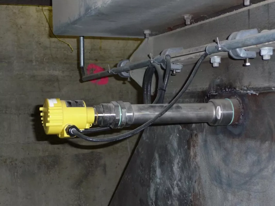
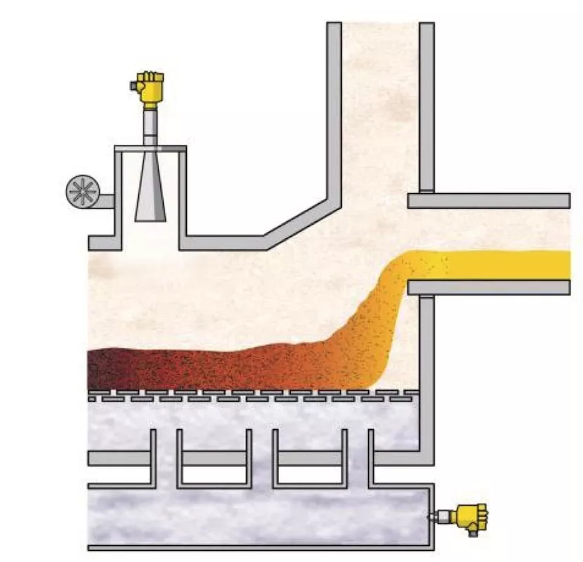
Fig. 2: Microwave barrier with tube extension for temperature decoupling in a clinker cooler.
|
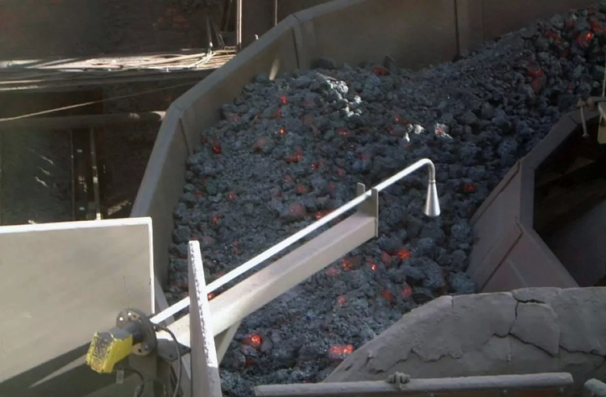
Fig. 3: Radar sensor with antenna extension for measuring hot sinter in steel production.
|
The tube inner diameter must be adjusted to the frequency of the sensor and processed so that there are no disturbing features (weld beads, gaps, etc. ) at the joints. To ensure optimal performance, antenna extensions should be provided by the sensor manufacturer and the sensors adapted to the respective antenna systems. Customised design of tubular extensions with any necessary bends and special high-temperature antenna systems is possible, see Fig. 3.
Unique Applications
Complex applications often require a customisation of the sensor for an optimal technical solution – here is where a flexible sensor system is needed. Thanks to their modular concept, standard radar sensors from VEGA can be adapted to widely different applications. Costs thus remain within reasonable limits because only small adaptions have to be carried out. The physical advantages of microwaves can be utilised without having to re-engineer the sensor completely.
One great advantage of radar technology is that microwaves propagate without being affected by dust. Reliable measurement is therefore possible even under conditions of extreme dust generation.

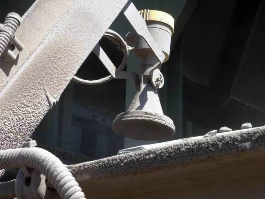
Depending on the process conditions, a certain amount of dust will inevitably be deposited on the sensor; whether this interferes with the measurement in the long term, however, depends on the particulars of the application. In most applications the sensors operate reliably and without maintenance despite heavy soiling (Fig. 4).
Antenna covers of various materials are available to help avoid excess soiling of the antenna system. In addition to protective caps of PP or PTFE, there are flexible fabric covers that can be cleaned pneumatically with a short air pulse. This consumes considerably less air than continuous air rinsing and results in significant savings in the costs associated with air supply. The different covers are easy to retrofit and can be simply mounted when needed.
It is vitally important to protect the electronics of sensors, especially in applications with high temperatures. Antenna extensions allow the electronics to be detached and installed in a “safe” place. The extensions can be straight, curved or segmented to suit the specific application.
In applications with high temperatures, the usual antenna systems with PTFE components quickly reach their limits. Versions with high-temperature resistant plastics such as PEEK or even ceramic are available for such cases. They can be used in process temperatures up to 450 °C.
To ensure that the antennas function optimally even in the highest of process temperatures, high-temperature resistant materials as well as solid die-cast antennas are available.
High Temperature Examples
After burning, the clinker, i. e. the unground cement, is cooled. This involves loading the material, which has a temperature of up to 1500 °C, onto a conveyor belt with continuous air flow-through.
Radar sensors measure the thickness of the layer and thus enable efficient cooling.
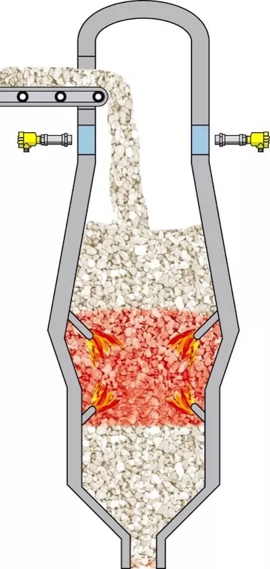
Another good example is level measurement in a lime kiln. Here, a microwave barrier can be used for non-contact measurement. The sensors measure the filling right through the firebrick lining (Fig. 6).
The measuring system operates without any physical contact with the abrasive material, so it is completely wear free and keeps maintenance costs to a minimum.
An example for measurement in heavy dust environments is the continuous level measurement in crushers.
Fig. 7 shows a radar sensor with a plastic encapsulated antenna which is used to monitor the filling of a crusher in a copper mine. Despite heavy dust deposits on the antenna system, the system – a Vegapuls 67 – detects the level reliably and accurately.
Effects on Costs
Using standard sensors and adapting them to the process via simple mechanical components keeps investment costs within reasonable limits. In many cases there is no need for costly, specially designed parts or setups.
Non-contact measurement ensures reliable operation and a long service life of the equipment. Sensor maintenance is reduced to a minimum. Altogether, these advantages result in significant cost savings.
■
