

Re: Plastic Foils Pneumatic Conveying
I think you need to look at RV more closely. First off all the 200 mbar pressure loss figure for RV is probably 10 times higher. There are losses in RV but normally they are taken as acceleration losses as the material is accelerated to max velocity. For this product / conveying conditions you are looking at about 20-30 mbar.
Similarly at 2 tph you are looking at about 9 m3/hr volumetric flow rate and with the 400 m3/h RV air leakage it must be a massive beast. You have not mentioned the size of RV ? For these rates you are looking at DN 250 – 300 RV and RV leakage of 100-120 m3/hr.
For the given conveying route / rate and working on pick up velocities of 13-16 m/s you are looking at 200 mbar total system pressure drop. Since the end is under 60 mbar vacuum you can rate the blower at 250-300 mbar to include safety factor. ■
Re: Plastic Foils Pneumatic Conveying
Dear Mantoo
thank you very much for the reply and your valuable insigths!
indeed I have to confess I've missed some additional informations:
1. The plastic foils are from selected waste shredded with a rotary shredded. The size is not regular as well as the material type max. size is 40 mm.
2. The material tend to be sticky due to some organic matter and other hygroscopic material still in the mixture.
3. Usually pick up velocities for such mixed material are abt. 28-30 m/s , i.e. velocity of the flow in the pipe.
4. We chose DN 100 mm due to the burner (it has a channel that can get a DN 100 pipe).
5. Yes the RV is a massive beast! The beast is a blow through RV with a flange 900 x 600. The RV is flanged to a dosing belt with a width of 1200 mm. Everything was oversized in order to avoid having material stucked or oversized material not injected into the burner.
6. RV supplier advise us abt. the DP along blow through pipe, but we have some doubts... as you correctly stated! ■
Re: Plastic Foils Pneumatic Conveying
Dear Mr Palazzolo,
If I understand correctly, your system comprises:
Aerzen GM25 blower ---> air pipeline ---> Rotary Valve line feeder of 400 m3/hr ---> convey pipeline ---> burner.
The Aerzen GM25S blower can deliver 1368 m3/hr at 1000 mbar and 1452 m3/hr at 300 mbar.
The RV is feeding the plastic foil into the conveying pipeline.
At that location, the plastic foil has to be accelerated (as Mr Mantoo already stated).
This acceleration will create a pressure drop, which must be accounted for in your calculations.
At the same time, the RV will transport air from the high pressure in the convey line to the RV inlet and air will leak also along the rotor vanes.
This RV leakage reduces the airflow in the convey pipeline, which also has to be accounted for in your calculations.
The RV leakage is depending on the pressure in the convey pipeline, RV volume and RV rpm..
Here, you will encounter a calculation problem, because the RV leakage changes the convey air rate.
As the convey air rate changes, the pressure and thereby the leakage of the RV changes also.
This creates a loop of events.
Iteration is the key to a solution.
Success ■
Teus
Re: Plastic Foils Pneumatic Conveying
Dear Mr. Tuinenburg,
Yes you got the point ! but the problem is that i have only (I can model..) leakage air vs. Pressure inside the line, but I have some problem in how to model the concentrated pressure loss due to the presence of the RV blow through.
The supplier has told me that for such huge RV (400 m3/h evaluated at RV inlet is the leakage air if the pressure inside is approx. 1,7 mbar (abs.) ) has a 200 mbar DP !
I want to assume an inverse quadratic dependence of leakage air flowrate vs. pressure inside (Q leakage = k*sqrt(P)).
What do you think?
We can easily insert such iteration in excel file!
TKS ■
Acceleration Pressure Drop
Dear all,
I'm a mister Palazzolo colleague and, following your suggestion, I calculated pressure drop due to solid particle acceleration.
Using this formula:
Delta(p)=(0.5+fluid dinamic viscosity*solid velocity/air velocity)*air density*air velocity^2
Where:
Solid velocity=air velocity*(1-0.68*particle diameter^0.92*air density^-0.2*solid density^0.5*pipe diameter^-0.54)
Using this kind of formulas I found a prssure drop of 8.8 mbar but we have still to understand the other 200 mbar losses told by the supplier.
Thans to all
Francesco ■
Acceleration Pressure Drop
Sorry
I posted the same text two time by mistake ■
Re: Plastic Foils Pneumatic Conveying
Dear Mr Palazzolo and Francesco,
Consider the blow through insert as a pipe section (or as an intake).
I is not clear how the supplier defines the circumstances or conditions of the 200 mbar pressure drop.
Knowing the derivation of the 200 mbar could explain the difference.
I am still puzzled.
Is the 200 mbar the pressure drop over the air inlet and the air/product mixture outlet or over the RV inlet and the RV outlet?
400 m3/hr leakage at d(p) = 200 mbar at 1.7 mbar(abs)?
Does this mean; almost absolute vacuum at RV inlet (1.7 mbar(abs)) and 201.7 mbar(abs) at RV outlet?
Rotary lock volume loss can be calculated as the mass difference between a pocket under RV outlet pressure and a pocket under RV inlet pressure + gap losses.
I don’t think this will be an inverse quadratic relation.
Solid particle acceleration should be calculated with: * mass * (v2^2 – v1^2)
success ■
Teus
Re: Plastic Foils Pneumatic Conveying
Dear Teus,
thank you for replying.
I'll try to fullfill you doubt.
1. 200 mbar DP is over the RV inlet and the RV outlet
2. 400 m3/h leakage is with 1400 m3/h at RV inlet with a relative pressure of +700mbar and encountering a material flux of 2 ton/h or 10 m3/h. Mixture ari+ material, according to the supplier, are at a RP of +500 at the RV outlet
3. a question, v2=solid veolcity (4m/s) and v1=0 in this way I found a 16 mbar loss for acceleration
Thank you one more time
Francesco ■
Re: Plastic Foils Pneumatic Conveying
Dear Mr rpalazzolo75
Usually pick up velocities for such mixed material are abt. 28-30 m/s , i.e. velocity of the flow in the pipe.
I was just wondering where does 28-30 m/s pick up velocity figure comes from ? system will work reliably at half of it. ■
Re: Plastic Foils Pneumatic Conveying
Dear Francesco,
Attached a drawing, representing the situation as I understand.
The convey air mass = 1000 * 1.2 = 1200 kg/hr = 1.2 tons/hr
SLR = 2 / 1.2 = 1.67
With such a low SLR (much air and low material mass) a low acceleration pressure drop can be expected.
My calculation gives 3.3 mmWC (#0.33 mbar) as dp(acceleration) for 0 to 4 m/sec)
====================================
This is excluding other partial pressure drops.
=====================================
As your air velocity is approx 23 m/sec, I would expect a higher product velocity, which of course would create a higher pressure drop. (f.i. (18/4)^2 * 3.3 = 66 mmWC (# 6.6 mbar)
BR
Attachments
■
Teus
Re: Plastic Foils Pneumatic Conveying
Dear Mr. Mantoo
28-30 m/s is the flow velocity for plastic waste shredded with maximum size 40 mm. This velocity has proven to be optimal for this waste in several cement plant co-incineration sites
Regards ■
Re: Plastic Foils Pneumatic Conveying
Dear Teus,
How do you calculate solid velocity?Because, with formula I wrote in this thread I calculated 4/5 m/s.
Concerning your PDF I have to say you understood well the situation, even if you draw a "shoe" rotary valve instead of the "blow through" rotary valve we have; except this everything is correct and we could't know how to verify leakage air and pressure losses supplier told us.
BR
Francesco ■
Re: Plastic Foils Pneumatic Conveying
Dear Francesco,
I did not calculate the product velocity but in this case guessed 18 m/sec.
The calculation of v-product is a lot of (computer) work.
First calculate the acceleration, based on suspension velocity, gas conditions (p,T,V) and relative velocity.
Then calculate the acquired velocity
Then calculate the velocity drop as a result of collisions (product resistance).
Then repeat this calculation.
When the velocity drop equals the velocity gain, then a “steady state” situation is reached.
The product velocity does not increase anymore.
(Although this “steady state” situation does not really exists, because of increasing air velocity as a result of expanding air due to pressure drop along the pipeline, both velocities increase steadily)
These complex physical phenomena make pneumatic conveying so interesting
Regarding the calculation of rotary lock leakage, you can try the attachment.
BR
Attachments
■
Teus
Re: Plastic Foils Pneumatic Conveying
Dear Mr. Mantoo
28-30 m/s is a proven value on several cement plant in co-incineration asset on waste plastic max. size 40 mm
regards ■
Re: Plastic Foils Pneumatic Conveying
Dear Teus,
I have to search for a couple of information about data needed according to your calculation.
I will do acceleration and leakage calculation this evening and I hope we could discuss tomorrow basing on a new data-sheet similar to the one Mr Palazzolo attached in first message with these new data.
I wuold like to thank you one more time for fullfilling our doubts
BR
Francesco ■
Re: Plastic Foils Pneumatic Conveying
Dear Teus,
As I said I've done calculation you suggested me for solid veolcity and rotary valve leakage air.
In attached Pneumatic transport 1 you find calculation with air flow rate at blower 1400 m3 with 500 mbar(g) head (values supplier told us), a leakage in rotary valve of 270 Nm3/h (according to your fromulas). Rotary pressure drop is 200 mbar according to supplier indication.
You can see solid velocity of 26-30 m/s, but with air speed of 44-53 m/s.
Thus we can't reach this kind of air speed we tried other combination such as 1000 m3 with 400 mbar(g) head, a leakage of 40 Nm3/h. I kept rotary valve drop pressure of 200 mbar even if I think it could drop.
You can see solid velocity of 21-25 m/s, with air speed of 37-45 m/s.
I would like to have an opinion from you because, using figures of model 1 or 2 means great differences in installed power for blower and great velocity differences.
BR
Francesco
Attachments
■
Re: Plastic Foils Pneumatic Conveying
Re: Plastic Foils Pneumatic Conveying
Dear Francesco,
i already modelled your pipeline in the computer.
Particle size 6mm (6000 micron) should give a suspension velocity of approx 5.5 m/sec
An air velocity of 15 m/sec should be enough.
Although I am not familiar with your calculation method, I cannot find the product factor (K?) for the plastic foil.
It seems to be 0.
Have you already calculated the air only pressure drop?
That pressure drop could be a significant value already
If you have field data of existing installation, I can calculate back the product losses and use the derived product loss factor for the new calculations.
Also the size of the rotarylock and the rpm are then required.
Teus ■
Teus
Re: Plastic Foils Pneumatic Conveying
Dear Teus,
medium particle size is 6 mm but I did my calculation with maximum size value that is 20mm with terminal velocity approx. 10,6 m/s.
Minim conveying velocity should be around 30 m/s.
With product factor for the plastic foil you mean friction factor (fmat in my calculation) or a coefficient for concentrated losses?
You find attached PDF with air only pressure drop.
Unfortunately I don't have field data for you.
Rotary lock volume=0,32 m3 calculated with pocket volume*n° pockets (10)
RPM=1
Francesco
Attachments
pneumatic transport 1 (only air) (PDF)
■
Re: Plastic Foils Pneumatic Conveying
Re: Plastic Foils Pneumatic Conveying
Dear Francesco,
I modeled the pipeline and using
v-suspension = 5.2 m/sec
and
2 tons/hr at 4000 mmWC
I calculated the required solid loss factor (for my algorithm) and found that this factor has to be negative ( - 0.0019)
The empty pipeline pressure drop is calculated as 352 mbar, which corresponds more or less with your spreadsheets.
The rest of the available pressure drop has to be spend on:
acceleration of 2 tons/hr
lifting of 2 tons/hr
keeping the 2 tons in suspension for 1 hr
and then there is not enough pressure drop available for product resistance.
Actually the product has to deliver energy to complete the energy balance
This is of course not possible.
Francesco
PRODUKT :Plastic foil
Pipeline capacity ....------------------....= 2.00 ton/hr
System-pressure.(airlock)--------------.= 4000. mmwC
Convey Length ------------------------ = 64 m
Number of Bends---------------------- = 3 -
D-begin =100 D-end =100
Ambient temperature ..-----------....= 40.0 °C
Q-pump.............----------------.......= 0.340 m^3/s
Q-convey-pipe ...---------------.........= 0.369 m^3/s
Outlet force .. ---------------------- = 150 N
loading-ratio .......---------------.....= 1.33 - - (dynamic)
T-plastic foil -------------------------- 71.5/ 45.0 Deg.C
T-out compressor ----------------------= 143. Deg.C
Reynoldsnumber ..[ Re ].-----------..= 2.91 --
Compr power ...----------------------..= 24. kW
spec.energy-consumption.----------..= 12.00 kWh/ton
p-accel.excl.prod.resist-----------.= 477. mmwC
p-suspension.....--------------........= 33. mmwC
p-lifting............-----------------....= 15. mmwC
p-airfriction.....---------------.......= 3121. mmwC
p-productresistance..-----------....= -211. mmwC
p-intake productcolumn...--------= 100. mmwC
p-intake ..........----------------......= 353. mmwC
Mass in pipeline.--------------------= 1 kg
p-nozzle ..............----------------..= 545. mmwC
p-filter..............------------------...= 79. mmwC
Empty pipe dp...--------------------.= 3526 mmWC
density product/air mix---------- ..= 2.8 kg/m^3
As my calculation is based on the outcome of your calculation one of them (or both) is (are) not correct.
I am short of pressure drop (211 mmWC) and your program uses approx 500 mmWC.
We both do not know the real product loss factor.
The rotary lock leakage seems to be very small, I come back on that later on.
we have to sleep on this one
have a good night sleep
teus ■
Teus
Re: Plastic Foils Pneumatic Conveying
Dear Francesco,
The rotary lock losses are in the order of 16 to 17 m3/hr
see attached file
BR
teus
Attachments
■
Teus
Re: Plastic Foils Pneumatic Conveying
Dear Teus,
I agree with calculation you did and corrected my data sheet with your leakage for rotary valve.
The problem is that I don't know how to update the field "rotary valve internal losses" that was given by supplier. They told us is 200 mbar according to a 400 m3/h leakage (other figure thy told us), but, correcting air leakage, I think it could decrease.
This pressure drop figure include air entrance in rotary valve through 3 noozle, confluence air/air losses, I think also solid acceleration pressure drop (even if I calculated it separately) and all other kind of losses you could have due to rotary valve.
BR
Franceso
Attachments
pneumatic transport corrected (PDF)
■
Re: Plastic Foils Pneumatic Conveying
Dear francesco,
The density of 200 kg/m3, as given in the spreadsheet calculation, is it
- bulk density or meterial dnesity ?
The bulk density is lower, because of the voids between the particles.
This is important for the estimate of the suspension velocity.
greetings ■
Teus
Re: Plastic Foils Pneumatic Conveying
Your are right,
I forgot to tell you it's a bulk density
BR ■
Re: Plastic Foils Pneumatic Conveying
Dear Francesco,
Can you post a picture of the material and mention the material density?
We get this thing sorted out.
Up to the next step
teus ■
Teus
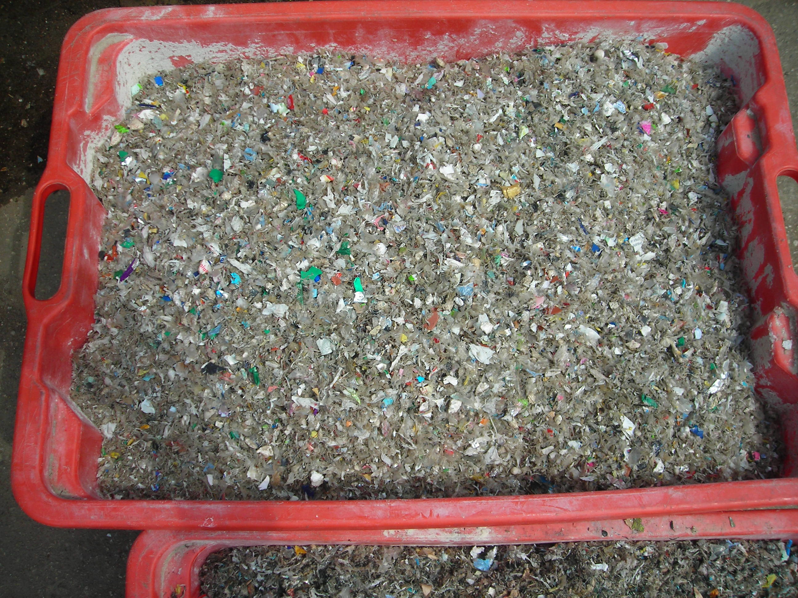
Re: Plastic Foils Pneumatic Conveying
Dear Teus,
sorry, but I wasn't able to reply you quicker.
Material density is 800 Kg/m3
Bulk density is 220 Kg/m3
Here is one picture of this kind of material, even if this is 13mm max. instead of 20 mm.
BR
Francesco ■
Re: Plastic Foils Pneumatic Conveying
Hello Francesco,
First the rotary lock.
The capacity is 0.32 * 1 * 220 *0.8 * 60 = 3400 kg/hr
This is divided in batches of 3400 / 60 / 10 = 5.6 kg per pocket
Considering that there is only abt 1 kg in the pipeline under way, this seems to become an instantaneous Solids Loading Ratio overload.
The material density of 800 kg/m3, results in a higher suspension velocity of
5.2 * SQRT(800/200) = 10.4 m/sec
The chosen velocities still may be OK.
A picture, supposed to go with your reply seems to be missing.
Still puzzled by the product loss factor.
Is it possible that the creator of your spreadsheet gives some support?
have a nice day
teus ■
Teus
Re: Plastic Foils Pneumatic Conveying
Good morning Teus,
sorry for missing picture.
Maybe there was a misunderstanding: we have done this spreadsheet that is absolutely correct concerning air part but it was corrected by myself for material losses part according to some formulas I found on scientific articles, but our biggest problems were:
1. see how this 200 mbar losses in the rotary valve happens (remember this data were told by supplier and I made it work increasing a K factor for concentrated losses)
2. see where 400 m3/h leakage came from? (with your help I understood they were maybe oversized)
3. see if assumptions I made for material losses were correct
have a nice day
Francesco
Attachments
■
Re: Plastic Foils Pneumatic Conveying
Dear Francesco,
Thanks for the picture.
The shape is flat chips, which indicates a high drag factor and as a result of this. the suspension velocity will not be so high.
Assumed is v-suspension = approx 6 m/sec
A solid loss factor of 0,01 is also assumed. (Only applicable in my program)
It appears that the air friction loss is dominant in this calculation, which can be expected of the high velocities and the low SLR.
Therefore the air volume choice (or pipe diameter) is very important.
I did 2 calculations: air volume 0.34 m3/sec and 0.17 m3/sec
For the results see the attachment.
It is noticed that the chosen air volume has a big influence on the conveying pressure at a capacity of 2 tons/hr
NOTE:
As all the used figures are a (educated) guess, these calculations can NOT be the basis for implementation. More data have to be obtained or measured and verified.
This thread shows how difficult it is to get the figures right in pneumatic conveying.
And the gap losses of the rotary lock are not yet solved.
success
teus
Attachments
■
Teus
Re: Plastic Foils Pneumatic Conveying
Hello Francesco, hello Teus,
It seesm the rotary air lock is the most challenging unknown variable in terms of air loss and pressure drop. The manufacturer's assumptions seem to be based on some sort of maximum operating conditions that are not meaningful unless all his assumptions are made available to you. Can your RV suplier help you out with more specific data as they pertain to your your system?
Is this an existing installation, or a potential installation? If it is an existing one, you could rent an additional PD blower with variable speed drive and tie it into the current blower header pipe. The beauty of this would be for you to "dial" in the air flow you need to get the material flow rate. Once you know the blower RPM, you will easily get to know your total air flow requirements and in essence you would finally get to know more about your air lock losses and pressure drop as well. Once you are done with the test you would have options to update your blower package, e.g. new package, additional blower etc.
One place where you could go for a blower or compressor rental would be AIR BV, which has depots all over Europe.
http://dut-nl.aerzen.com/index.php/c...view/full/1105
I would not recommend using a conventional plant air compressor that the usual rental places carry in inventory. The have the disadvantage of potential moisture drop out into your pipe work, usually there is no std. over pressure protection (at your system level), and you would not be able to regulate the flow much and definetely not get to know your air flow.
I believe in the practical approach of a pneumatic system as well as doing the theoretical homework, such as what you are doing now. By renting the equipment you would not put too much capital into the system development and thus lower your overall costs. Just a thought. ■
Re: Plastic Foils Pneumatic Conveying
Dear Ralph,
thank you for your suggestion but unfortunately it' s a potential installation and all you said will be done in a tuning phase, and our goal would be finding something similar to what could happen just in order to buy correct things.
BR
Francesco ■
Fancesco84
Dear All,
Francesco has quitted our company, hence pls. refer to myself for anything,
Wish all the best to Francesco in his new job!
Ciao to all ■

Plastic foils pneumatic conveying
Dear All
we are involved into the pressure drop calculation of a conveying line for 2 ton/h of plastic foils (< 20 mm) with a density of 220 kg/m3.
The line is formed by the following items:
1. Blower (Aerzen GM 25)
2. Bend (1x Diam)
3. Horizontal 1,5 m
4. Bend 1 x Diam
5. rotary valve blow through (leakage air 400 m3/h)
6. Horizontal 2 m
7. BEnd 15 x Diam
8. Vertical 8 m
9. Bend 15 x Diam
10. Horizontal 51 m
11 Bend 15x Diam
12 Horizontal 2,3 m
13. Inlet burner flange (Interna Diam. 100 mm and Pressure -60 mbar(g) )
The idea is to choose a flowrate of 1400 m3/h inlet air.
But we have some problem in calculating rotary valve concentrated pressure loss . The supplier said 200 mbar .
Attached find enclosed our calc. sheet
Anyone has ideas on how to model blow through rotary valve pressure loss (pipe side) ?
Thanks a lot
Attachments
pneumatic transport (PDF)
■